Towards a methodology for rigorous development of
generic requirements patterns
1Colin Snook1, Michael Poppleton1, and Ian Johnson2
1 School of Electronics and Computer Science, University of Southampton,
SO17 1BJ, UK, cfs,[email protected] 2 AT Engine Controls, Portsmouth, UK
Abstract. We present work in progress on a methodology for the engineering, validation and verification of generic requirements using domain engineering and formal methods. The need to develop a generic requirement set for subsequent system instantiation is complicated by the addition of the high levels of verification demanded by safety-critical domains such as avionics. We consider the failure detection and management function for engine control systems as an application domain where product line engineering is useful. The methodology produces a generic requirement set in our, UML based, formal notation, UML-B. The formal verification both of the generic requirement set, and of a particular application, is achieved via translation to the formal specification language, B, using our U2B and ProB tools.
Introduction
The notion of software product line (also known as system family) engineering be-came well established [14], after Parnas’ proposal [18] in the 70’s of information hid-ing and modularization as techniques that would support the handlhid-ing of program families. Product line engineering arises where multiple variants of essentially the same software system are required, to meet a variety of platform, functional, or other requirements. This kind of generic systems engineering is well known in the avionics industry; e.g. [12, 10] describe the reuse of generic sets of requirements in engine control and flight control systems.
Domain analysis and object oriented frameworks are among numerous solutions proposed to product line technology. In Domain-Specific Software Architecture [23] for example, the domain engineering of a set of general, domain-specific requirements for the product line is followed by its successive refinement, in a series of system en-gineering cycles, into specific product requirements. On the other hand [11] describes the Object-Oriented Framework as a “a reusable, semi-complete application that can be specialized to produce custom applications”. Here the domain engineering
duces an object-oriented model that must be instantiated, in some systematic way, for each specific product required. In this work we combine object-oriented and formal techniques and tools in domain and product line engineering.
It is widely recognized that formal methods (FM) technology makes a strong con-tribution to the verification required for safety-critical systems [15]. It is further rec-ognized that FM will need to be integrated [3] in as “black-box” as possible a manner in order to achieve serious industry penetration. The B method of J.-R. Abrial [1, 19] is a formal method with good tool support [2, 8], and a good industrial track record, e.g. [9]. At Southampton, we have for some years been developing an approach of in-tegrating formal specification and verification in B, with the UML [7]. The UML-B [22] is a profile of UML that defines a formal modelling notation combining UML and B. It is supported by the U2B tool [20], which translates UML-B models into B, for subsequent formal verification. This verification includes model-checking with the ProB model-checker [13] for B. These tools have all been developed at Southampton, and continue to be extended in current work.
Failure detection and management for engine control
A common functionality required of many systems is to detect and manage the failure of its inputs. This is particularly pertinent in aviation applications where lack of toler-ance to failed system inputs could have severe consequences. The failure manager filters inputs from the controlled system, providing the best information possible and determining whether a transducer or system component has failed or not.
Inputs may be tested for magnitude, rate of change and consistency with other puts. When a failure is detected it is managed in order to maintain a usable set of in-put values for the control subsystem and provide ‘graceful degradation’. To prevent over-reaction to isolated transient values, a failed condition must be confirmed as per-sistent before irreversible action is taken. Failure detection and management (FDM) in engine control systems is a demanding application area, see e.g. [6], giving rise to far more than a simple parameterizable product line situation.
Fault Tolerance
This application domain (and our approach to it) includes fault tolerant design in two senses: tolerance to faults in the environment, and in the control system itself. The FDM application is precisely about maximizing tolerance to faults in the sensed en-gine and airframe environment. The control system (including the FDM function) - is supported by a backup control system in a dynamically redundant design. This backup system - with distinct hardware/software design, with a reduced-functionality sensing fit - can be switched in by a watchdog mechanism if the main system has failed.
In the narrower (and more usual) sense, we will be examining various schemes for designing fault tolerance into the FDM software subsystem. Work to date has speci-fied and validated a generic requirements specification for FDM. As we apply refine-ment techniques and technology to construct the design, we will consider various relevant approaches, such as driving the specification of a control system from envi-ronmental requirements [25], or the use of fault-tolerant patterns for B specifications [27] and their refinements [26].
Methodology
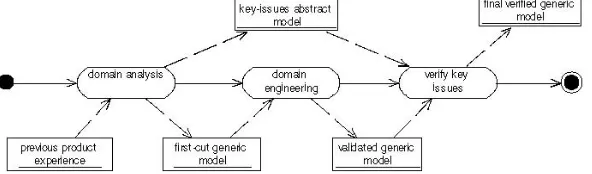
The process for obtaining a generic model of requirements is illustrated in Fig. 1. The first stage is an informal domain analysis which is based on prior experience of devel-oping products for the application domain of failure detection and management in en-gine control. A taxonomy of the kind of generic requirements found in the application domain is developed and, from this, a first-cut generic entity-relationship model is formed by naming and relating the generic requirements.
[image:3.595.152.448.581.668.2]The identification of a useful generic model is a difficult process warranting further exploration. This is done in the domain engineering stage where a more rigorous ex-amination of the first-cut model is undertaken, using UML-B, U2B and ProB. The model is animated by creating typical instances of its generic requirement entities, to test when it is and is not consistent. This stage is model validation by animation, using the ProB and U2B tools, to show that it is capable of holding the kind of information that is found in the application domain. During this stage the relationships between the entities are likely to be adjusted as a better understanding of the domain is devel-oped. This stage results in a validated generic model of requirements that can be in-stantiated for each new application.
For each new application instance, the requirements are expressed as instances of the relevant generic requirement entities and their relationships, in an instance model. The ProB model checker is then used to automatically verify that the application is consistent with the relationship constraints embodied in the generic model. This stage, producing a consistent instance model, shows that the requirements are a consistent set of requirements for the domain. It does not, however, show that they are the right set of requirements that will give the desired system behaviour.
Our aim in future work, therefore, is to add dynamic features to the instantiated model in the form of variables and operations that model the behaviour of the entities in the domain and to animate this behaviour so that the instantiated requirements can be validated. We would prefer to add this behaviour in the generic model so that it too can be re-used by the instantiated model.
During the domain analysis phase we found that considering the rationale for re-quirements revealed key issues, which are properties that an instantiated model should possess. Key issues are higher level requirements that could be expressed at a more abstract level from which the generic model is a refinement. The generic model could then be verified to satisfy the key issue properties by proof or model checking. This matter is considered in [21] which gives an example of refinement of UML-B models in the failure management domain.
The final stage is to validate the specific configuration. This would be done by pro-viding actual values to generic behaviours when the generic mode is instantiated. The resulting specific model could then be animated to validate its behaviour.
Finally, we recognize the need for tools to support uploading of bulk system in-stance definition data, as well as the efficient and user-friendly validation/ debugging of said data. ProB could easily be enhanced to provide, for example, data counterex-amples explaining invariant violations.
Domain Analysis
To obtain an initial understanding of the requirements domain we used domain analy-sis in a similar style to Lam [12]. The first step was to define the scope of the domain in discussion with engine controller experts. An early synthesis of the requirements and key issues were formed, giving due attention to the rationale for the requirements. Considering the requirements rationale is useful in reasoning about requirements in the domain [12]. For example, the rationale for confirming a failure before taking ac-tion is that the system should not be susceptible to spurious interference on its inputs. From the consideration of requirements rationale, key issues were identified which served as higher level properties required of the system. An example of such a prop-erty would be that the failure management system must not be held in a transient ac-tion state indefinitely. The raac-tionale from which it has been derived is that a transient state is temporary and actions associated with this state may only be valid for a lim-ited time.
types have been further subsumed into a general detection type. This type structure provided a taxonomy for classification of the requirements.
Domain analysis showed that failure management systems are characterised by a high degree of fairly simple similar units made complex by a large number of minor variations and interdependencies. The domain presents opportunities for a high degree of reuse within a single product as well as between products. For example, a magni-tude test is usually required in a number of instances in a particular system. This is in contrast to the engine start domain addressed by Lam [12], where a single instance of each reusable function exists in a particular product. Our methodology is targeted at domains such as failure management where a few simple units are reused many times and a particular configuration depends on the relationships between the instances of these simple units. A first-cut entity relationship model was constructed from the units identified during the domain analysis stage. The entities identified during domain analysis were:
• INP Identification of an input to be tested.
• COND Condition under which a test is performed or an action is taken. (A
predi-cate based on the values and/or failure states of other inputs).
• DET Detection of a failure state. A predicate that compares the value of an expres-sion to be tested against a limit value.
• CONF Confirmation of a failure state. An iterative algorithm performed for each
invocation of a detection, used to establish whether a detected failure state is genu-ine or transitory
• ACT Action taken either normally or in response to a failure, possibly subject to a condition. Assigns the value of an expression, which may involve inputs and/or other output values, to an output.
• OUT Identification of an output to be used by an action
Domain Engineering
The aim of the domain engineering stage is to explore, develop and validate the first-cut generic model of the requirements into a validated generic model. At this stage this is essentially an entity relationship model, omitting any dynamic features (except temporary ones added for validation purposes).
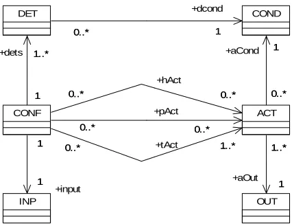
OUT COND DET 1 0..* +dcond 1 0..* ACT 1 1..* +aOut 1 1..* 1 0..* +aCond 1 0..* INP CONF 1 1..* 1 +dets 1..* 1..* 0..* +tAct 1..* 0..* 0..* 0..* +pAct 0..* 0..* 0..* 0..* +hAct 0..* 0..* 1 1 +input 1 1
Fig. 2. Final UML-B version of generic model of failure management requirements
The model was tested by adding example instances using the animation facility of ProB and examining the values of the B variables representing the classes and asso-ciations in the model to see that they developed as expected. ProB provides an indica-tor to show when the invariant is violated. Due to the ‘required’ (i.e. multiplicity greater than 0) constraints in our model, the only way to populate it without violating the invariant would be to add instances of several classes simultaneously. However, we found that observing the invariant violations was a useful part of the feedback dur-ing validation of the model. Knowdur-ing that the model recognises inconsistent states, is just as important as knowing that it accepts consistent ones. The model was re-arranged substantially during this phase as the animation revealed problems. Once we were satisfied that the model was suitable, we removed the constructor operations to simplify the corresponding B model for the next stage.
The next stage is to add behaviour to the generic model by giving the classes op-erations. In future work we will investigate the best way to introduce this behaviour during the process. It may be possible to add the behaviour after the static model has been validated as described above. Alternatively, perhaps the behaviour will affect the static structure and should be added earlier. In either case, we aim to formalise the ra-tionale described in the domain analysis and derive the behaviour as a refinement from this.
Requirements for a specific application
[image:6.595.198.411.153.316.2]tabular form. The generic model provides a template for the construction of the tables. Each class is represented by a separate table with properties for each entry in the table representing the associations owned by that class. The tabular form is useful as an ac-cessible documentation of the application but is not directly useful for verification. To verify its consistency, the tabular form is translated into class instance enumerations and association initialisation clauses attached to the UML-B class model. This is done manually, which is tedious and error prone, but automation via a tool is envisaged.
ProB is then used to check which conjuncts of the invariant are violated. For our FDM example, several iterations were necessary to eliminate errors in the tables be-fore the invariant was satisfied. Initially, testing of the instantiation caused an invari-ant violation. The ProB ‘analyse invariinvari-ant’ facility provides information about which conjuncts of the invariant are violated. For example, a few conjuncts from the FDM example are shown:
(ACT:POW(ACT_SET)) == TRUE (OUT:POW(OUT_SET)) == TRUE
(aOut:TotalSurjection(ACT,OUT)) == false (aCond:(ACT-->COND)) == false
We found that the analyse invariant facility provided useful indication of where the invariant was violated (i.e. which conjunct) but, in a data intensive model such as this, it is still not easy to see which part of the data is at fault. It would be useful to show a data counterexample to the conjunct (analogous to an event sequence counterexample in model checking). This is another area for potential tool support.
Classification of problems
It would be useful to classify the kinds of problems found during animation and veri-fication in order to better understand the source of problems and improve the re-quirements engineering process. So far, we have found that problems can be classified on a methodological stage basis. Possible categories on this basis, some of which we have experienced, are as follows.
• Verification of generic model – the generic model is inconsistent or incor-rect
• Validation of generic model – the generic model is correct and consistent but does not reflect the generic requirements
• Validation of generic requirement – the generic model works as expected but animation leads expert to review generic requirements
• Verification of instantiation - the instantiation is inconsistent with the ge-neric model because of an incorrect instantiation
• Verification of instantiation - the instantiation is inconsistent with the ge-neric model because the gege-neric model is inadequate
• Validation of specific requirements - the instantiation is consistent with the generic model but animation leads expert to review specific require-ments
In the future, when behavioural features are modelled, we expect to find other ways of classifying problems. For example we may be able to distinguish functional areas that are prone to incorrect specification.
Conclusion
In this paper we have discussed a product-line approach to the rigorous engineering, validation and verification of generic requirements for critical systems such as failure management and detection for engine control. The approach can be generalised to any relatively complex system component where repetitions of similar units indicate an opportunity for parameterised reuse but the extent of differences and interrelations be-tween units makes this non-trivial to achieve. The product-line approach amortises the effort involved in formal validation and verification over many instance applications. So far we have considered the static, entity-relationship features of the requirements. In future work we aim to extend the approach to consider also the detailed meaning (i.e. dynamic behaviour) of these entities.
Two broad areas of future work are indicated by the case study, both linking to re-lated work on Product Line Engineering (PLE). The first concerns instance data man-agement, the second variability vs. commonality in the generic model.
For a product family such as FDM at ATEC as currently envisaged, instance data management is in principle straightforward. This is because no system in-stance/variant requirements are defined at the generic level – all structure and behav-iour is specified in terms of a single generic model. Instance/variant requirements are captured completely by instance-level data. This means that all instance data struc-tures are defined in terms of the generic class definitions. Therefore, the data for a system instance is simply defined as a subset of the database of all required instance specifications; tooling is thus a straightforward database application.
Instance management becomes more complex when variability is required in the generic model. This is the usual state of affairs in PLE. The mobile phone scenario of [16] is typical, where each system instance is defined by a distinct set of functional features, aimed at a specific market segment and target price. Features are not in gen-eral simply composable, and the totality of features cannot in gengen-eral be specified in one generic model: variability specification is required in the generic model. To date approaches to this (such as [16]) have been in the obvious syntactic form: in ATEC for example, variants on the generic model for other engine manufacturers might be described as extra colour-coded classes, associations, states, events etc. A system variant (or sub-family) would thus be defined in terms of some colour-combination submodel. A more sophisticated metamodelling approach to variability specification, based on the Model-Driven Architecture of the OMG, has recently been proposed [17].
application of refinement approaches to PLE to date has been modest, e.g. [5, 24], and has, in our view, much potential. Retrenchment, a generalizing theory for refinement, has been investigated in a feature engineering context [4], and may well also be useful in PLE.
References
[1] J.-R. Abrial. The B-Book: Assigning Programs to Meanings. Cambridge University Press, 1996.
[2] J.-R. Abrial. http://www.atelierb.societe.com/index uk.html, 1998. Atelier-B.
[3] P. Amey. Dear sir, Yours faithfully: an everyday story of formality. In F. Redmill and T. Anderson, editors, Proc. 12th Safety-Critical Systems Symposium, pages 3–18, Birmingham, 2004. Springer.
[4] R. Banach, M. Poppleton. Retrenching Partial Requirements into System Definitions: A Simple Feature Interaction Case Study, 2003, Requirements Engineering Journal Vol. 8 (4) [5] D. Batory, J.N. Sarvela, and A. Rauschmayer, Scaling Step-Wise Refinement, IEEE
Trans-actions on Software Engineering (IEEE TSE), June 2004
[6] C.M. Belcastro. Application of failure detection, identification, and accomodation methods for improved aircraft safety. In Proc. American Control Conference, volume 4, pages 2623– 2624. IEEE, June 2001.
[7] G. Booch, I. Jacobson, and J. Rumbaugh. The Unified Modeling Language -a Reference Manual. Addison-Wesley, 1998.
[8] D. Cansell, J.-R. Abrial, et al. B4free. A set of tools for B development, from http://www.b4free.com, 2004.
[9] B. Dehbonei and F. Mejia. Formal development of safety-critical software systems in rail-way signalling. In M.G. Hinchey and J.P. Bowen, editors, Applications of Formal Methods, chapter 10, pages 227–252. Prentice-Hall, 1995.
[10] S.R. Faulk. Product-line requirements specification (PRS): an approach and case study. In
Proc. Fifth IEEE International Symposium on Requirements Engineering. IEEE Comput. Soc, Aug. 2000.
[11] M. Fayad and D. Schmidt. Object-oriented application frameworks. Communica-tions of the ACM, 40(10):32–38, Oct. 1997.
[12] W. Lam. Achieving requirements reuse: a domain-specific approach from avionics. Jour-nal of Systems and Software, 38(3):197–209, Sept. 1997.
[13] M. Leuschel and M. Butler. ProB: a model checker for B. In K. Araki, S. Gnesi, and D. Mandrioli, editors, Proc. FME2003: Formal Methods, volume 2805 of LNCS, pages 855–874, Pisa, Italy, September 2003. Springer.
[14] R. Macala, L. Jr. Stuckey, and D. Gross. Managing domain-specific, product-line develop-ment. IEEE Software, pages 57–67, May 1996.
[15] UK Ministry of Defence. Def Stan 00-55: Requirements for safety related software in de-fence equipment, issue 2. http://www.dstan.mod.uk/data/00/055/02000200.pdf, 1997. [16] D. Muthig. GoPhone - A Software Product Line in the Mobile Phone Domain,
IESE-Report No. 025.04/E (Fraunhofer Institut Experimentelles Software Engineering, 2004 [17] D. Muthig and C. Atkinson. Model-Driven Product Line Architectures, In G.J. Chastel
(Ed.): Software Product Lines, Second International Conference, SPLC 2002, Proceedings. LNCS 2379 Springer 2002, pages 110-129
[18] D. L. Parnas. On the design and development of program families. IEEE Transactions on Sofkvare Engineering, SE-2, March 1976.
[20] C. Snook and M. Butler. U2B -a tool for translating UML-B models into B. In J. Mermet, editor, UML-B Specification for Proven Embedded Systems Design, chapter 5. Springer, 2004.
[21] C. Snook, M. Butler, A. Edmunds, and I. Johnson. Rigorous development of reusable, domain-specific components, for complex applications. In J. Jurgens and R. France, editors,
Proc. 3rd Intl. Workshop on Critical Systems Development with UML, pages 115–129, Lis-bon, 2004.
[22] C. Snook, I. Oliver, and M. Butler. The UML-B profile for formal systems modelling in UML. In J. Mermet, editor, UML-B Specification for Proven Embedded Systems, chapter 5. Springer, 2004.
[23] W. Tracz. DSSA (Domain-Specific Software Architecture) pedagogical example. ACM Software Engineering Notes, pages 49–62, July 1995.
[24] A. Wasowski. Automatic generation of Program Families by Model Restrictions, In R.L. Nord (Ed.): Software Product Lines, Third International Conference, SPLC 2004, Proceed-ings. LNCS 3154 Springer 2004, pages 73—89
[25] I.J. Hayes, M. A. Jackson, and C. B. Jones, Determining the specification of a control sys-tem from that of its environment, In K. Araki, S. Gnesi, and D. Mandrioli, editors, Proc. FME2003: Formal Methods, volume 2805 of LNCS, pages 154–169, Pisa, Italy, September 2003. Springer.
[26] L. Laibinis and E. Troubitsyna, Refinement of fault tolerant control systems in B Source: Computer Safety, Reliability, and Security. 23rd International Conference, SAFECOMP 2004. Proceedings (Lecture Notes in Comput. Sci. Vol.3219), 2004, p 254-68 [27] L. Laibinis and E. Troubitsyna, Fault tolerance in a layered architecture: a general