UNIVERSITI TEKNIKAL MALAYSIA MELAKA
COMPARISON STUDY BETWEEN HSC 70 WITH DMU 60 EVO
USING POWERMILL SOFTWARE ON SIMULTANEOUS
5-AXIS MACHINING PART
This report submitted in accordance with requirement of the Universiti Teknikal Malaysia Melaka (UTeM) for the Bachelor’s Degree in Manufacturing Engineering
Technology (Process and Technology) with Honours
by
MOHAMAD FARID BIN MAHADI
B071410673
930922-03-5391
ii
DECLARATION
I hereby, declared this report entitled “Comparison Study between HSC 70 with DMU 60 EVO Using PowerMILL Software on Simultaneous Five-Axis Machining Part” is the results of my own research except as cited in references.
Signature :………
Name : MOHAMAD FARID BIN MAHADI
iii
APPROVAL
This report is submitted to the Faculty of Engineering Technology of UTeM as a partial fulfillment of the requirements for the degree of Bachelor of Manufacturing Engineering Technology (Process) (Hons.). The member of the supervisory is as follow:
……….
iv
ABSTRAK
v
ABSTRACT
In this study, information, journal and articles regarding the title which is “Comparison Study between HSC 70 with DMU 60 EVO Using PowerMILL Software on Simultaneous Five-Axis Machining Part” have been searching and used for better knowledge and understanding. In further research, some problem occurred on machining part due to machining strategy and post-processor. The objective of this study is producing impeller using two CNC machine and inspect the accuracy of the part machined have been investigated. Impeller CAD model has been selected from GrabCAD website. Unfortunately, the CAD model must be made major modification due to the limitation of the CNC machine and machine tools. Then, the impeller has been designed using Solidwork software to fulfill the limitation of the machine. Aluminium 5053 is used as raw material to machine impeller. HSC 70 and DMU 60 EVO is used in machining impeller and the machining program been created using PowerMill software. In PowerMill software, cutting strategies been used to machine the part is roughing, model area clearance, blisk area clearance, hub finishing, blade finishing, surface projection and surface finishing. After physical machining processes, the part has been inspecting using 3D Scanner machine and its methodology. The scan data from 3D Scanner be converted in the 3D model. The comparison of 3D model and scan 3D model been compared using Geomagic Control X software. Some recommendations have been made to improve this study in future. The recommendations are limitation of tools and analysis method.
vi
DEDICATIONS
vii
ACKNOWLEDGMENTS
I would like to express deepest gratitude to my supervisor Mr. Muhammad Syafik B. Jumali for her full support, expert guidance, understanding and encouragement throughout my study and research. Without her incredible patience and timely wisdom and counsel, my thesis work would have been a frustrating and overwhelming pursuit. In addition, I express my appreciation to Mr. Syahrul Azwan Bin Sundi@Suandi for becoming the co-supervisor. His thoughtful question and comments were valued greatly.
Thanks also go to my fellow friends at the Faculty of Technology Engineering of University Technical Malacca. Special thanks go to them who helped me throughout this academic exploration.
viii
TABLE OF CONTENTS
DECLARATION ii
APPROVAL iii
ABSTRAK iv
ABSTRACT v
DEDICATIONS vi
ACKNOWLEDGMENTS vii
TABLE OF CONTENTS viii
LIST OF FIGURES xi
LIST OF ABBREVIATIONS, SYMBOLS AND NOMENCLATURES xvii
CHAPTER 1 1
INTRODUCTION 1
1.1 Background Study 1
1.2 Problem Statement 3
1.3 Objectives 1
1.4 Scope 1
CHAPTER 2 2
LITERATURE REVIEW 2
2.1 Five-Axis Machining 2
2.1.1 DMG Mori HSC 70 Linear 4
ix
2.2 Toolpath Generation 7
2.3 CAD/CAM 8
2.3.1 Autodesk PowerMILL 9
2.4 Ball-End Milling Machining 10
2.5 Turbine Blade 12
2.6 Coordinate Measuring Machine (CMM) 14
2.6.1 Coordinate Measuring Machine Probe 15
2.6.2 Measurement strategies 17
2.7 Aluminium 18
CHAPTER 3 21
METHODOLOGY 21
3.1 Project Planning 22
3.2 Phase I 24
3.2.1 Problem Simulation 24
3.2.2 Literature Review to Better Understand the Study. 24
3.2.3 Searching and Draw Suitable CAD Model 25
3.2.4 Import the 3D Model into PowerMILL Software 26
3.3 Phase II 27
3.3.1 Material and Suitable Cutting Tool 27
3.3.2 Preparation of CAM Program 29
3.3.3 Jig and Fixture Preparation 40
3.3.4 Post-Processing 41
x
3.3.6 Dimensional Analysis 43
CHAPTER 4 46
RESULT AND DISCUSSION 46
4.1 Result 46
4.2 Data Analysis for Turbine Blade Machined by DMU 60 EVO 49 4.3 Data Analysis for Turbine Blade Machined by HSC 70 57
4.4 Comparison analysis of Both Machine Part 65
4.5 Machined Part Problem 69
CHAPTER 5 71
CONCLUSION AND FUTURE WORK 71
5.1 Conclusion 71
5.2 Future Work 72
REFERENCES 73
xi
LIST OF FIGURES
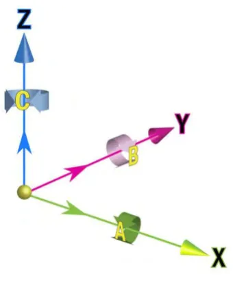
Figure 2.1 Cartesian Coordinate system ... 3
(Adapted from Hurco North America)... 3
Figure 2.2(a): HSC 70 Linear ... 4
(Adapted from http://en.dmgmori.com) ... 4
Figure 2.2(b): HSC 70 Linear Controller and Monitor ... 5
(Adapted from http://en.dmgmori.com) ... 5
Figure 2.3: DMU 60 EVO Linear ... 6
(Adapted from http://en.dmgmori.com) ... 6
Figure 2.4: (a) Original tool orientation (b) tool orientation after optimize ... 7
(Adapted from (Hu et al., 2016)) ... 7
Figure 2.5(b): Cutter Contact, Cutter location and cutting tool reference point. ... 8
(Adapted from (K and Lazoglu, 2017)) ... 8
Figure 2.6: shown that iso-scallop for curvature part ... 9
(Adapted by (Lin et al., 2014)) ... 9
Figure 2.7(a) shown the cutting of Ball End Mill...10
(Adapted from (Chao and Altintas, 2016)) ...10
xii
(Adapted from (Li et al., 2015)) ...11
Figure 2.7(c): Extraction of entry/exit angles using arc-surface intersection method. ...11
(Adapted from (Li et al., 2015)) ...11
Figure 2.7(d): Toolpath of cutting impeller ...12
(Adapted from (Li et al., 2015)) ...12
Figure 2.8(a): Blade after roughing without finishing. ...13
(Adapted from (Arriaza et al., 2017)) ...13
Figure 2.8(b): Toolpath for machining mesh of blade ...13
(Adapted from (Vavruska, 2016)) ...13
Figure 2.9(a): The axis of Coordinate Measuring Machine ...14
(Adapted (Ferreira et al., 2013)) ...14
Figure 2.9(b): CMM measuring Table and Coordinate. ...15
(Adapted from (Sudatham et al., 2016)) ...15
Figure 2.10(a): Universal high precision reference spheres, silicon nitride (left) and quartz glass (right). ...16
(adapted from (Thalmann et al., 2012) ) ...16
Figure 2.10(b): Probe Direct contact on curve surface ...16
(Adapted From (Wang et al., 2017)) ...16
Figure 2.11: General flow Chart to present work ...17
(Adapted from (Rajamohan et al., 2011)) ...17
xiii
(Adapted from http://www.azom.com) ...20
Figure 3.1 Flow Chart Methodology ...22
Figure 3.2: 3D CAD Model ...26
Figure 3.2 (a): Block Setting Toolbar ...26
Figure 3.2 (b): Cylinder Block ...27
Figure 3.3: Detail Regarding Cutting Tool ...29
Figure 3.4: List of Tool Used ...29
Figure 3.5(a) Setting of Coordinate system ...30
Figure 3.5(b) Flow Chart of CAM Machining Processes ...31
Table 3.6: Setting of First Roughing Process ...32
Table 3.7: Setting of Second Roughing Process ...33
Figure 3.8(a) : First Roughing ...33
Figure 3.8(b) : Second Roughing ...34
Figure 3.9: Model Area Clearance Setting ...34
Figure 3.10: Model Area Clearance ...35
Figure 3.11: Blisk Area Clearance Setting ...35
Figure 3.12 Blisk Area Clearance ...36
Figure 3.13 Hub Finishing Setting...36
Figure 3.14 Hub Finishing ...37
Figure 3.15: Blade Finishing Setting ...37
xiv
Figure 3.17 Surface Projection Setting ...38
Figure 3.18 Surface Projection ...39
Figure 3.19 Surface Finishing Setting ...39
Figure 3.20 Surface Finishing ...40
Figure 3.21(a): LANG Makro Grip Vice 125 ...40
Figure 3.21(b): Vice Detail Drawing ...41
Figure 3.21(c): Turbine Blade Attached To Vice ...41
Figure 3.22: NC Program ...42
Figure 3.23 Cylinder Block with the slot. ...43
Figure 3.24(a) Applied Spraying Substance on Turbine Blade (HSC 70) ...44
Figure 3.24(b) Applied Spraying Substance on Turbine Blade (DMU 60 EVO) ...45
Figure 3.24(c) 3D Scanner Machine ...45
Figure 4.1 Result of CAM Program Simulation ...46
Figure 4.2(a) Physical Machining Result Using HSC 70 ...47
Figure 4.2(b) Physical Machining Result Using DMU 60 EVO ...47
Figure 4.3(a): Result of 3D Scanner for HSC 70 ...48
Figure 4.3(b): 3D Scanner result for DMU 60 EVO ...48
Figure 4.4 Reference Data ...49
Figure 4.5 Measured Data ...50
Figure 4.6 Initial Alignment ...50
xv
Figure 4.8: 2D Compare Section ...52
Figure 4.9: Point Taken at Section 1 ...52
Figure 4.10 Point Taken at Section 2 ...53
Figure 4.11 Point Taken at Section 3 ...53
Figure 4.12 Gap Thickness of the Blade Surface for Section 1 ...54
Figure 4.13 Error Bar Chart for Section 1 ...54
Figure 4.14 Gap Thickness of the Blade Surface for Section 2 ...55
Figure 4.15 Error Bar Chart for Section 2 ...55
Figure 4.16 Gap Thickness of the Blade Surface for Section 3 ...56
Figure 4.17 Error Bar Chart for Section 3 ...56
Figure 4.18 Reference Data ...57
Figure 4.19 Measured Data ...58
Figure 4.20 Initial Alignment ...58
Figure 4.21 Comparison Accuracy of 3D CAD Model And 3D Scanner Model...59
Figure 4.22: 2D Compare Section ...60
Figure 4.23: Point Taken at Section 1 ...60
Figure 4.24: Point Taken at Section 2 ...61
Figure 4.25: Point Taken at Section 3 ...61
Figure 4.26: Gap Thickness of the Blade Surface for Section 1 ...62
Figure 4.27: Error Bar Chart for Section 1...62
xvi
Figure 4.29: Error Bar Chart for Section 2...63
Figure 4.30: Gap Thickness of the Blade Surface for Section 3 ...63
Figure 4.31: Error Bar Chart for Section 3...64
Figure 4.32: Overall Gap Thickness of DMU 60 EVO Machined Part ...65
Figure 4.33: Error Bar Chart of Overall Gap Thickness for DMU 60 EVO Machined Part ...66
Figure 4.34: Overall Gap Thickness for HSC 70 Machined Part ...66
Figure 4.35: Error Bar Chart of Overall Gap Thickness for HSC 70 Machined Part.67 Figure 4.36: Comparison for Both Machined Part ...67
Figure 4.37: Comparison Bar Chart for Both Machined Part ...68
Figure 4.38: Machined Part Problem for DMU 60 EVO ...69
Figure 4.39: Hub Finishing and Blade Finishing Tolerance Setting ...69
xvii
LIST OF ABBREVIATIONS, SYMBOLS AND
NOMENCLATURES
CAM = Computer Aided Manufacturing
CAD = Computer Aided Design
3D MODEL = Three-Dimensional Model
2D = Two-Dimensional
NC = Numerical Control
CNC = Computer Numerical Control
IGES = Initial Graphic Exchange Specification STEP = Standard Exchange of the Product Model
STL = Standard Triangle Language
UTEM = Universiti Teknikal Malaysia Melaka
CMM = Coordinate Measuring Machine
1
CHAPTER 1
INTRODUCTION
1.1 Background Study
In the era of technology rapidly developing, many machines have been created to fulfill a human need, reduce human efforts and improve production efficiency and productivity. Machining operation was divided into two type that is conventional machining and non-conventional machining. Many industries today using a machine that can be controlled by computers. This is because to reduce defects products and produce high quality of products. But, these machines are very costly. It also needs high skill workers to operate this machine. This machine advantage is it can reduce production time, reduce defects, and can have a high accuracy of machining parts.
Advanced manufacturing typically offers competitive wages, contributes handsomely to regions gross regional product, and offers job opportunity for workers with a wide variety of education and skills including many middle-skill jobs. Because of that, professionals on workforce development, economic development, and higher education are fighting to make their community well suited for advanced manufacturing. Advanced Manufacturing technology is a family of activities that depend on the use and coordination of information, automation, computation, software, sensing, and networking, and make use of cutting-edge materials and emerging capabilities enabled by the physical and biological sciences, for example, nanotechnology, chemistry, and biology.
2 can understand and execute. This language was developed originally to machine parts directly to what that has been settings by the programmer. This code will be created using CAD/CAM software. CNC is the complexity of high accuracy in the minimum that commonly used in the today’s world. CNC also can be controlled in term of feed rate, spindle speed and the axis of this machine.
CAD/CAM software stands for Computer Aided Design/ Computer Aided Manufacturing are very important in advanced manufacturing today. CAD is a software to design products such as electronic, aerospace parts and automobile parts. From CAD design, the 3D computer model data will be converted to appropriate CAM format. CAM is a software to create tool paths and NC code to run a CNC controlled machine. In CAM software, the cutting strategy can be settings to reduce tools wear and avoid cutting marks on the machined part.Nowadays, these are an example of CAD and CAM software that commonly used in manufacturing such as CATIA and SolidWorks by Dassault Systemes. Another example is Inventor and PowerMill by Autodesk.
Turbine Blade or Impeller has a complex geometry that cannot be machined by using only 3-axis machining or any other method of machining. An impeller usually made from of iron, steel, bronze, brass, aluminium and plastic. The traditional process to create an impeller is using casting process. The metal has been melted to a high temperature to be in molten state. The molten metal will be poured into the mold that has formed to shape an impeller. However, the fabrication of turbine blades by investment casting is a very complex process, and the shrinkage during casting is highly nonlinear (Yiwei et al., 2017).
3 1.2 Problem Statement
Nowadays, technology became one of the country economy or worldwide business. A product that is created from manufacturing technology being import or export to increase country economy. So that, many machines to create these product has been imported. There are so many five-axis machines be created these days such as Mazak, Kitamura Five-axis machine, and DMG Mori. Most of the people know about the existence of this machine, but they do not know truly how many they were created. Five-axis machine has several of the models that have a different configuration and different machining command.
Turbine blades or impeller has a very complex geometry that hard to be machined. The blade has very thin layer and curvature from bottom to top. Although this impeller can be made using casting process, it has a bad surface finish. It also has crack and porosity because of the casting process. Many processes have to be done to make the perfect product of impeller. It will increase production time and cost.
1 1.3 Objectives
The project objective that has been determining are: 1. To machine impeller using HSC 70.
2. To machine impeller using DMU 60 EVO.
3. To compare the dimensional accuracy of both machines.
1.4 Scope
Scopes for this project is based on objectives that have stated and there are the several scopes that will be carrying out:
1. The machine that will be compared is DMU 60 EVO and HSC 70 linear. 2. Programming (CAM) will be done using PowerMILL Software with
customized postprocessor.
2
CHAPTER 2
LITERATURE REVIEW
In this chapter are about all finding that been obtained from many sources such as a journal, article, books, the internet and the topic that related to this study. The finding is the guideline to complete this study. This section includes the five-axis machining, aluminium and turbine blade.
2.1 Five-Axis Machining
3 Descartes was lying in bed (as mathematicians and philosophers are wont to do) when he observed a fly buzzing around his room. Descartes recognized that he could describe the fly’s position in the room’s three-dimensional space using just three numbers, embodied by the variables X, Y and Z. (Rene Descartes, 1569-1650).
Figure 2.1 Cartesian Coordinate system (Adapted from Hurco North America)
4
2.1.1 DMG Mori HSC 70 Linear
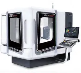
HSC 70 linear is the five-axis that is created to reduce human effort and easy to machine a single part in less time. The machine is more precision and has better surface quality for the die and mold industry. The thermo symmetric machine bed in bridge type design forms the basis for highest long-term accuracy. This will be further amplified by the innovative cooling concept. New HSC spindles with shaft, flange and jacket cooling ensure thermal stable process conditions and an up 70 % lower axial tool expansion.
Figure 2.2(a): HSC 70 Linear (Adapted from http://en.dmgmori.com)
[image:24.595.197.480.285.539.2]