Iowa State University Patents
Iowa State University Research Foundation, Inc.
2-14-2006
Apparatus and method for reducing anhydrous
ammonia application by optimizing distribution
H. Mark Hanna
Iowa State University
Paul M. Boyd
Iowa State University
Follow this and additional works at:
http://lib.dr.iastate.edu/patents
Part of the
Agriculture Commons
, and the
Bioresource and Agricultural Engineering Commons
This Patent is brought to you for free and open access by the Iowa State University Research Foundation, Inc. at Iowa State University Digital Repository. It has been accepted for inclusion in Iowa State University Patents by an authorized administrator of Iowa State University Digital Repository. For more information, please [email protected].
Recommended Citation
Hanna, H. Mark and Boyd, Paul M., "Apparatus and method for reducing anhydrous ammonia application by optimizing distribution" (2006).Iowa State University Patents. 298.
(12)
United States Patent
Hanna et al.
US006997400B1
(10) Patent N0.:
(45) Date of Patent:
US 6,997,400 B1
Feb. 14, 2006
(54)
(75)
(73)
(21)
(22)
(60)
(51)
(52)
(58)
(56)
APPARATUS AND METHOD FOR REDUCING ANHYDROUS AMMONIA APPLICATION BY OPTIMIZING DISTRIBUTION
Inventors: H. Mark Hanna, Urbandale, IA (US);
Paul M. Boyd, GlenWood, IA (US)
Assignee: Iowa State University Research
Foundation, Inc., Ames, IA (US)
Notice: Subject to any disclaimer, the term of this patent is extended or adjusted under 35
U.S.C. 154(b) by 56 days.
Appl. No.: 10/620,925
Filed: Jul. 16, 2003
Related US. Application Data
Provisional application No. 60/396,763, ?led on Jul.
17, 2002.
Int. Cl.
B05B 1/34
(2006.01)
B05B 3/04
(2006.01)
B05B 3/16
(2006.01)
A01C 23/00
(2006.01)
A62C 2/08
(2006.01)
US. Cl. ... .. 239/383; 239/381; 239/548;
111/119
Field of Classi?cation Search ... .. 239/383,
239/381, 548, 142, 159, 172, 380, 382, 389,
239/214.15, 662; 137/561 A; 111/119
See application ?le for complete search history.
References Cited
U.S. PATENT DOCUMENTS
2,973,728 A * 3/1961 Garretson ... .. 111/119
4,807,663 A * 2/1989 Jones ... .. 137/561A
5,170,820 A * 12/1992 Jones . . . . . . . . . . .. 137/899 5,271,567 A * 12/1993 Bauer . . . . . . . . . . .. 239/662
5,372,160 A * 12/1994 Ward ... .. 137/561A 6,003,534 A * 12/1999 Gould etal. ... .. 137/1 6,202,942 B1* 3/2001 Hultgreen et a1. 239/214.15
OTHER PUBLICATIONS
CDS-John Blue Company Introduces The “EXacto-FloW”
FD-1200 and FD-2000 FloW Dividers, Brochure, Undated (2
pages).
H. I. Fraser PTY LTD., The Trangie Rota?oW, Anhydrous
ammonia distribution technology, Brochure, Undated (4
pages).
“The Trangie Rota?oW ®” and Anhydrous Ammonia
Distribution Technology, Brochure, Undated, (2 pages).
Fraser “Rota?oW Anhydrous DistributionTechnology—Performance Under Pressure”, Brochure (6
pages).
(Continued)
Primary Examiner—David A. Scherbel
Assistant Examiner—Darren Gorman
(74) Attorney, Agent, or Firm—McKee, Voorhees & Sease,
P.L.C.
(57)
ABSTRACT
An apparatus, method, and system for distributing gas and/or liquid phase substance from an inlet to multiple
outlets With reduced variations and distribution. The appa ratus includes a body having an inlet and a plurality of outlets. In one aspect, a rotatable impeller is positioned
betWeen inlet and plurality of outlets. The impeller includes
a spiral ?uid pathway relative to direction of substance through the inlet so that the substance passes through the impeller and is distributed to the outlets through a spinning
impeller.
60 Claims, 12 Drawing Sheets
INJECTION KNIFE
U.S. Patent
Feb. 14, 2006
Sheet 1 0f 12
US 6,997,400 B1
84
a
‘2
<=>
=
c: Q a
[[11-
'
w?‘
s9
22
“8°
80
10
INJECTION
KNIFE
U.S. Patent
Feb. 14, 2006
Sheet 3 0f 12
US 6,997,400 B1
FIG. 2A
22
FIG. 2C
14
U.S. Patent
Feb. 14, 2006
Sheet 5 0f 12
US 6,997,400 B1
FIG. 2F
20
U.S. Patent
Feb. 14, 2006
Sheet 7 0f 12
US 6,997,400 B1
FIG. 3D
FIG. 3C
32
FIG. 3F
U.S. Patent
Feb. 14, 2006
FIG. 40
Sheet 9 0f 12
US 6,997,400 B1
FIG. 4B
46
FIG. 40
12:.
57
FIG. 4E
"Kim
53
57
FIG. 4F
50
‘
v"//////'
‘51
FIG. 6A
72
e4
/
W/JL l//// c'1///////1@\
18
6°
62
U.S. Patent
Feb. 14, 2006
Sheet 11 0f 12
US 6,997,400 B1
92
94
60
\
94
US 6,997,400 B1
1
APPARATUS AND METHOD FOR REDUCING ANHYDROUS AMMONIA
APPLICATION BY OPTIMIZING DISTRIBUTION
I. CROSS-REFERENCE TO RELATED APPLICATIONS
This application claims bene?t under 35 USC § 119(e) of provisional application 60/396,763 ?led Jul. 17, 2002.
II. BACKGROUND OF THE INVENTION
Application or injection of chemicals, such as fertilizers,
on or into the soil, is commonly used to enhance groWth and
yield for agricultural plants. In come cases, such substances
are in ?uid-form (liquid or gaseous phase, as opposed to
solid phase). Apparatus is required to convey the substance
from a bulk storage container to the ground.
One example is the injection of anhydrous ammonia (NH3) (a gas at ambient temperatures and pressures) into the ground. Normally, the substance is kept under pressure in liquid phase in a large bulk holding container or tank. What
are called knives have discharge ends that are dragged
through the ground. Avalving and distribution system can be selectively operated to convey anhydrous ammonia from the
tank to the knives as the knives are dragged through the
ground to emplace the fertilizer in the ground. Nitrogen
fertilizer is a major input in terms of cost and energy in
production of major crops (e.g. corn, Wheat, cotton, rice).
Anhydrous ammonia is the most popular form of nitrogen
fertilizer application.
Physical properties of anhydrous ammonia can cause it to convert from a high pressure liquid to a mixture of liquid and
gas as it travels through application equipment. The mixture
is very dif?cult to evenly distribute to individual application knives across the sWath Width of the applicator. These distribution problems may be the cause of over-application. Because liquid ammonia is much more dense than gaseous
form, openings that receive greater proportions of liquid
ammonia Will distribute more nitrogen to their knives than
openings that receive greater proportions of gaseous ammo
nia. This results in often highly variable application across
the applicator sWath.
Normally some type of manifold is used to distribute anhydrous ammonia from the tank to a plurality of knives,
so that in one pass, a plurality of roWs can be fertilized.
During the past 10 years, neW loW pressure anhydrous ammonia manifolds have been developed. Each manifold
has some potential to improve upon the Widely varying
distribution of the 40-year-old “conventional” radial outlet manifold.
The present inventors conducted studies of several types
of commercially available distribution manifolds. Eight manifolds Were evaluated during ?eld application at appli
cation rates of 84 kg N/ha (75 lb N/ac) and 168 kg N/ha (150
lb N/ac). The actual ammonia stream from each outlet of the
manifold Was collected and Weighed after each run to
determine mean, % difference from mean, highest outlet to
loWest outlet Weight ratio, and the coef?cient of variation
(“CV”) for each run With 11 knife outlets. Results shoWed
that the use of the older “conventional” manifold can result in coef?cient of variation or CV values in excess of 30%. Some studies indicate as much as a four-to-one shank-to
shank output variation across an applicator. In general, all the neWer manifold designs tested reduced this value, some
achieving CV values in the 5% range. But some still have on 10 15 20 25 30 35 40 45 55 60 65
2
the order of tWo-to-one variation betWeen shanks. During
application the operator cannot tell if there is over- or
under-application. The term CV or coef?cient of variation,
as used herein, is in percentage as a statistical indicator of
variation in output of each manifold. The loWer, the better. The coef?cient of variation is a Well-knoWn indicator. (See,
e.g., Steel, R. G., J. H. Torrie, and D. A. Dickey. Principles and Procedures of Statistics: A Biometrical Approach. 3’d ed. McGraW-Hill Companies, Inc. NeW York. 1997 Pg.
26—27; and ASAE (American Society of Agricultural Engi
neers) S3862 DEC98 Calibration and Distribution Pattern
Testing of Agricultural Aerial Application Equipment,
ASAE—The Society for engineering and agricultural, food,
and biological systems, 2950 Niles Rd., St. Joseph, Mich.
49085-9659; and ASAE (American Society of Agricultural
Engineers) S341.3 FEB99 Procedure for Measuring Distri bution Uniformity and Calibrating Granular Broadcast
Spreaders, ASAE—The Society for engineering and agri
cultural, food, and biological systems, 2950 Niles Rd., St.
Joseph, Mich. 49085-9659).
The above-mentioned testing of existing distribution
manifolds shoW there is room for improvement in distribu
tion from the holding container to the application knives.
Even a reduction of a feW percent of anhydrous ammonia
use by improved application equipment and methods could materially decrease the amount of nitrogen release (includ
ing into surface and ground Water resources) as Well as cost
to the producers. Some of the existing distribution systems
tested (on a three-point DMI model 3250 anhydrous ammo
nia applicator) include:
Rota?oWTM from H. I. Fraser Pty LTD (Sydney, Australia)
—top feed rotary with How of material though impeller, not
outside it.
Equa?oWTM from PGI Intl.—Rotary outlets With internal cavity size manually controlled by user.
Vertical Dam designs (small and large, cotton or corn
rings) from Continental NH3 Products—ammonia enters
from side and sWirls into radial outlets.
Conventional manifolds (Model 3497) from Continental
NH3 Products (one With mixer; one With nipple; one With street elboW). Also, a COLD-FLO® System 16 (#20340 canister and separate 16 outlet distribution manifolds.) Also,
side entry linear and tee entry linear manifold designs and a
FD-1200 (CDS John Blue Co.) Were tested.
There is a need for optimization of distribution. Devel
opment of such a manifold is vital to the future use of this
fertilizer form in precision agriculture applications including
variable rate application and late spring side dressing of ammonia. Existing manifold designs exhibit noticeable
variation as they distribute anhydrous ammonia fertilizer to each of the injection knives on the toolbar applicator. This can lead in the ?eld to nitrogen de?ciencies, adversely
affecting yield or excesses, adversely affecting environmen
tal quality.
Four measures of variability among outlet distribution Were computed. Average outlet difference is the average absolute difference in kg(lb)NH3 of all outlets from the mean output of all outlets for a particular test plot. The average percentage outlet difference is the average of absolute outlet
difference from the mean outlet output expresses a percent age of a mean outlet output. This percentage measures use
to indicate the average percentage each outlet is from the
mean application rate and to normalize variability based on
the ammonia collected during each plot run. High/loW ratio
Further discussion of problems With present distribution
manifolds is set forth at “Rate Variability of Anhydrous
Ammonia Applicator Equipment”, ISU Extension publica
tion PM-1747, and “Improving the Uniformity of Anhy
drous Ammonia Application”, IoWa State University, Uni
versity Extension publication PM 1875 (June 2001), both
incorporated by reference herein.
Vertical dam manifolds and the COLD-FLO® system try
to solve the gas/liquid mixture problem by separating gas
and liquid phases and metering equal portions of each to
each knife.
III. BRIEF SUMMARY OF THE INVENTION
The present invention relates to a distribution manifold
for distributing a gas and liquid phase substance from a
single inlet to multiple outlets With reduced distribution
variation. In one aspect of the invention, an apparatus comprises a body, an inlet, a plurality of outlets, a ?uid pathWay betWeen inlet and outlets, and mechanism to move the exit of the pathWay in a controlled manner past the outlets. In one aspect, the mechanism is an impeller, being
rotatable and having a surface at an angle to How of the
substance (e.g. external ?ighting or a spiral groove), alloWs
the substance to pass from the inlet and at the surface as the
impeller rotates, to then distribute the substance to the outlets. Impeller rotation can be induced by pressure of the
incoming substance against the impeller surface(s). The
?uid pathWay can be multiple pathWays. Optionally, rotation
can be poWered by a motor or other actuator.
The method according to the invention includes placing,
in the delivery path of the substance, a member that moves the substance pathWay, by the outlets at a controlled rate. In one aspect, the member rotates in the path of the substance
prior to the substance reaching a plurality of distribution
20 25 30 35 40 45
FIGS. 3A—F installed in the body of FIGS. 2A—G, and also
illustrates ?ttings adapted for connection to individual hoses
or conduits to individual injections knives.
FIG. 8 is a partial sectional elevation of an alternative
embodiment of the invention.
V. DETAILED DESCRIPTION OF THE PREFERRED EMBODIMENT
For a better understanding of the invention, one exem
plary embodiment Will noW be described in detail. It is to be
understood that this is but one form the invention can take
and does not limit the scope of the invention. Variations obvious to those skilled in the art Will be included Within the invention.
A. General Environment of Use of the Invention
An embodiment of the invention is here referred to as
distribution manifold 10. Manifold 10 includes an input adapted to be connected to a pressuriZed source of anhy
drous ammonia (see FIG. 1B), and has a plurality of ?ttings 80 radially distributed around the manifold body 12 (see
FIG. 1A) that can be operatively connected to hoses 71
Which, in turn, are connected at distal ends to individual
injection knives for an anhydrous ammonia injection system (see FIG. 1B Where, for simplicity, just one ?tting 80 from
an outlet 22 is diagrammatically illustrated connected by a hose 71 to an injection knife).
Distribution manifold 10 can be used for anhydrous ammonia fertiliZer for agriculture. It uses an impeller 30 that
US 6,997,400 B1
5
B. Speci?c Apparatus Structural Components
More speci?cs of distribution manifold 10 can be seen in
the drawings. FIGS. 1A—C illustrate the pieces of distribu tion manifold 10. FIGS. 2 through 7 illustrate other speci?cs.
1. Body 12
The main pieces include cylindrical body 12 (eg aircraft
grade Aluminum 6061, approx. 12 inches long, 6 inches
O.D.) having an inlet 18 connectable by Well-known com
ponents to an anhydrous ammonia source. In this embodi
ment, the length of manifold body 12 is approximately one foot long, and its diameter is generally in the proportion
indicated in FIGS. 1A—C and 2A—G.
Manifold body 12 includes a central bore 24 connecting inlet 18 to a conical cavity 26 (see FIG. 1C and FIG. 2G). Radially disposed outlets 22 exist at end 16 of manifold
body 12 (see also FIGS. 2A—G). Outlets 22 extend from the
inside of the conical cavity 26 to the outer exterior of
manifold body 12. As shoWn in FIGS. 1A, 2A—B, and 7, ?ttings 80 (Well knoWn in the art) can be operatively
connected to outlets 22, and in turn each can be operatively
connected to a hose or conduit to an injection knife (also
Well knoWn in the art). 2. Impeller 30
An impeller 30 is insertable into conical cavity 26 of manifold body 12. In this example it is made of solid
glass-impregnated Te?on®(25% impregnated With glass
beads). Such material is relatively easy to machine and hasrelatively loW change in volume over a substantial tempera ture range. It is approximately 4 inches diameter at its base 38. It serves as an impeller that is relatively freely rotatable once installed in position in response to pressure of ?uid
(liquid or gas phase) through conduit 24. Spiral grooves or ?ighting 34 on the exterior of impeller 30 (a conical member Which closely matingly conforms to cavity 26—the slope of the exterior of impeller 30 and the slope of conical cavity 26
are the same), provides a ?uid pathWay from bore 24 to a distribution groove 36 in impeller 30. In this embodiment
there are three spiral grooves (each approximately 1.25 rotations and 120° apart on the exterior of the impeller) (See, e.g., FIG. 3D). Thus the NH3 has three spiral groove paths
to enter and traverse betWeen the tip 32 of impeller 30 and
its base (at distribution groove 36). Distribution groove 36 is positioned in the plane of radial outlets 22 of manifold
body 12 and is in concurrent ?uid communication With all outlets 22.
The distribution groove 36 sits at exactly the elevation of outlets 22 When the system is in operation and pressure of
incoming ?uid has pushed impeller 30 up to the top of body
12 (There is a small amount of longitudinal tolerance
betWeen impeller 30 and body 12). Distribution groove 36 is
fed by the exit ends of the three spiral grooves as they move material up from inlet 18. The ?uid pathWay betWeen inlet 18 and outlets 22 here is therefore split into three separate sub-pathWays or spiral grooves that can be called supply grooves. The supply grooves provide three sources to the distribution groove 36, at 120°‘ intervals. This alloWs for more even ?lling of distribution groove 36, than a single source Would and attempts to provide constant material quality (de?ned at a ratio of the material in the tWo masses;
quality=1 Would be all liquid, 0.0001 Would be all gas),
mass, and pressure to all outlets 22. Even if impeller 30 Were
to stop rotating, it provides three outlets to distribution ring
or groove 36 and then to outlets 22.
Impeller 30 is shoWn in more detail in FIGS. 3A—F. FIG.
3A shoWs, in perspective vieW, a rough prototype model. As
shoWn in FIG. 1C, once assembled, impeller 30 ?ts in
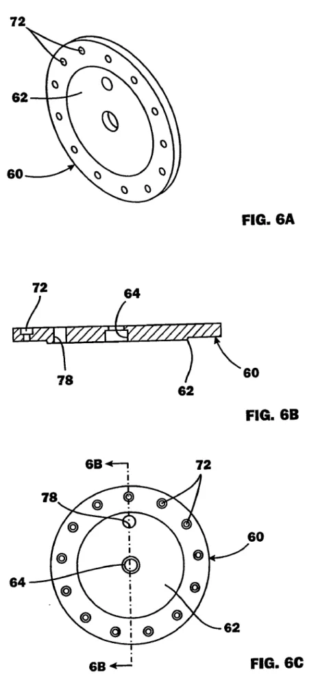
conical cavity 26. An end plate 60 (see also FIGS. 5 and
10 15 20 25 30 35 40 45 55 60 65
6
6A—C) is securable to manifold body 12 by bolts 70 through
bolt holes 72 into threaded apertures 25 in the face of end 16
of manifold body 12. An elastomeric O-ring 66 (eg Viton®
or buna-N) cooperates With a raised embossment 62 in end plate 60 and an O-ring receiving race 23 in the end base of 12 to provide a seal betWeen body 12 and end plate 60 once assembled.
3. Bearing Assembly 40 Generally (Including Ball 50)
Impeller 30 is held in rotatable fashion as folloWs. A
bearing apparatus (generally referred to at reference numeral
40 and shoWn more speci?cally at FIGS. 4A—H and FIG. 5), includes a threaded end 44 Which extends through center opening 64 in end plate 60 and can be secured there by nut
68. An opposite end 42 includes opposite ?attened portions
55, and a concave end face 53.
A pin 46 is interference ?ttable into a longitudinal
receiver bore 57 at the center of concave face 53 (see FIG.
4A).
A
bearing ball 50 (eg solid virgin Te?on®) is insertable
by interference-?t onto the other end of pin 46 by forcing pin 46 into bore 51. Bore 51 is completely through ball 50, but When assembled onto pin 46, pin 46 does not extend
completely through ball 50. Ball 50 is inserted on pin 46 to
Where it seats into concave 53. The curvature of concave 53
matches the exterior curvature of ball 50. The interference ?t of pin 46 in bore 57 and ball 50 onto pin 46 holds ball 50 in
place and deters rotation around pin 46. But this combina tion alloWs relatively easy removal and replacement of ball 50 (eg if it frictionally Wears over time) by simply pulling ball 50 off of pin 46 (overcoming the interference ?t).
As illustrated in FIG. 1B, a machine screW 52 is insertable into a central bore 33 (see FIG. 3E) in impeller 30 and can
be threadably screWed into threaded, reduced-diameter bore
35 at the inner end of central bore 33. ScreW 52 has a head that has a machined concave to match the curvature of ball 50. The concave in the head of screW 52 essentially Works as a bearing surface for ball 50.
Bearing assembly 40, With ball 50 installed on pin 46 and
seated in concave 53 (see FIG. 4A), can be inserted into center bore 33 of impeller 30. The diameter of ball 50 is slightly smaller than the diameter of bore 33 such that it passes into bore 33 Without interference. Assembly 40 can
be pushed doWn bore 33 until end plate 60 abuts the end 16
of body 12. As can be appreciated, the amount screW 52 is threaded into bore 35 determines hoW close its head Will be to ball 50 When manifold 10 is assembled. ScreW 52 is adjusted so that its head, speci?cally the concave of its head,
is closely adjacent ball 50 (eg approximately 1/8 inch). An
elastomeric O-ring 48 (eg Viton® or buna-N) can be installed in channel 47 of bearing assembly 40 to seal off
opening 64 in end plate 60 (see also FIGS. 4A—G and FIG.
5).
By referring to FIG. 5, once bearing assembly 40 is secured to end plate 60 and impeller 30 is in conical cavity
26, end plate 60 (With bearing assembly 40, including ball
50) is inserted, as described, such that ball 50 is positionedin bore 33 of impeller 30 and end plate 60 is secured to manifold body 12. As can be appreciated, the small tolerance
betWeen the head of screW 52 and ball 50 is designed so that
When pressuriZed NH3 enters bore 24, it travels up bore 24 and impacts the nose of impeller 30, and enters the spiral
groove of impeller 30. This creates an up-force on impeller
30 (in operational position it is vertically disposed, nose
doWn in body 12) as the pressuriZed ?uid hits the ri?ing or
?ighting (or Walls of spiral groove 34) of impeller 30 Which
re-assembly) along the longitudinal axis of the assembly 10
such that there is a slight longitudinal play betWeen ball 50
and the head of screW 52.
Referring also to FIG. 7, Which shoWs impeller 30 in
conical cavity 26, this arrangement alloWs relatively free
spinning of impeller 30 in manifold body 12 but seals any escape of ?uid from manifold body 12 other than through outlets 22 and ?ttings 80.
C. Operation
In operation, distribution manifold 10 is connected to an anhydrous ammonia source through inlet 18. Threaded bores 20 on the end face of end 14 of manifold body 12 can be
used to mount distribution manifold 10 to an implement.
Fittings 80 are installed in each radial outlet 22 in a sealing fashion. Hoses to injection knives are connected to ?ttings
80. By appropriate valving or other control systems, anhy
drous ammonia from its source ?oWs into inlet 18, doWn
conduit 24, and impacts the apex of impeller 30, entering the
channel formed by ?ighting or spiral groove 34. The pres sure (e.g. approx. 10—70 psi—pressure varies, including as
a function of tank pressure and ?eld conditions such as
temperature) of the anhydrous ammonia source relative to the angle of ?ighting or spiral groove 34 causes impeller 30
to spin. The anhydrous ammonia folloWs ?ighting or spiral
groove 34 up to distribution groove 36 in impeller 30, Which
is aligned With radial outlets 22, essentially distributing
anhydrous ammonia to each outlet 22 in sequence at the rate
of spin of the impeller 30.
A tachometer 83, connected by Wire 84 to a read-out or
other device, can be positioned in opening 78 on end plate
60 and used to monitor the speed of the impeller 30 (see FIG.
5).
In the exemplary embodiment, the design of impeller 30
includes a minimum of one rotation of ?ighting or spiral 20 25 30 35 40 45 50
is solely described by the claims herein.
The precise siZe and con?guration of distribution mani
fold 10 can be varied according to need. As indicated
previously, dimensions for exemplary embodiments have
been given and/or can be derived from the description and
?gures.
Other than the Te?on® parts, most of manifold 10 is made from aluminum. HoWever, the materials can be varied. For example, it is preferable that as loW a coef?cient of friction
as possible be created for bearing assembly 40. Materials
other than Te?on® could be used.
For further example, it is believed that manifold 10 can be
scaled up or doWn and be effective.
Also, it is possible to cause poWered rotation of impeller
30 by mechanical means (eg mechanical drive, electric or
gas-poWered engine, magnetic drive, etc.). FIG. 8 diagrams
a manifold 10 like previously described but With an electric
motor 90 (eg variable speed) operatively connected by
motor drive shaft 92 to impellor 30. Aseal 94 sends shaft 92.
HoWever, it is presently preferred to have impeller rotation poWered by pressure of the anhydrous ammonia itself. If
poWered otherWise, it could require a seal of a moving component (eg an axle) Which is dif?cult to do. It also is a
safety issue With anhydrous ammonia.
The impeller could have other groove con?gurations (e. g.,
one or more spiral groove(s) and at different pitches or
Widths).
More or less outlets 22 are possible, and outlets can be
plugged if not used.
E. Design Parameters
As can be appreciated, the invention can take different
embodiments and designs. Different desires and needs can result in different design criteria and goals. To assist in an
US 6,997,400 B1
the material to spin the impeller reduced sealing problems,
eliminated the need for an electrical supply for the manifold,
and reduced costs. The spinning created by the NH3 How
Was hoped to be suf?cient to evenly distribute the material to outlets arranged radially around the base of a cone shaped impeller. With an impeller driven by material ?oW as the
basic design selected, additional design parameters Were
evaluated.
Research shoWed consistently that eXisting manifolds With a cavity in the manifold Where the NH3 could eXpand
had poor distribution. This expansion area alloWs an initial
pressure, causing vapor production through boiling of the
NH3. The present manifold Was designed so the cross
sectional area for NH3 How Would remain constant from the point at Which material entered through a standard Acme ?tting to the point Where it left the manifold at the outlets.
For distribution systems using tank pressure to provide
NH3 ?oW, pressure drop through ?ttings and the regulator
had been shoWn to be signi?cant. This results in a miX of
NH3 in the liquid and vapor phases at the manifold. To reduce
the possible effect of uneven distribution due to tWo-phase How of the material, it Was decided that the material should enter the manifold from the bottom and eXit at the top.
Gravity Would help the chamber to ?ll With liquid from the bottom up. Vapor bubbles Would migrate to the top of the
manifold before moving out the outlets.
A test applicator used Was out?tted for 11 outlets. In
addition, the instrumentation to collect the temperature and pressure data for the manifold required an additional tWo
ports. Thus, thirteen ports Were used for the manifold design.
Hose barbs that Were 9.5-mm (0.38-in) outside diameter and 7.1-mm (0.28-in) inside diameter, common on NH3 mani
folds, Were used to standardiZe the manifold to mate With
eXisting hoses.
A 19.1-mm (0.75-in) Acme NH3 ?tting Was selected as the inlet ?tting. The 19.1-mm ?tting Was selected as it Would alloW for the How rate necessary for the application rate goal
Without the eXcess area of the common 25.4-mm (1.0-in) Acme ?tting. The cross sectional area of the inlet on the
19.1-mm ?tting Was 285-mm2 (0.430-in2). Throughout the
design, the total cross-sectional area through Which the material ?oWed Was limited to this value if possible.
The sum of the groove area in the impeller, and the sum of the area of the 13 outlets Were set Within an acceptable
range of 270 to 300-mm2 (0.421 to 0.438-in2). This range alloWed for any limitations in machining capability. Outlet
ports drilled With a 5.16-mm (13/64’h-in) drill resulted in a
total outlet area for 13 ports of 272-mm2 (0.422-in2).
Based on readily available material and the funds for manifold development, aluminum Was selected for the mani fold body, and Te?on® Was selected for the impeller cone.
Solid round stock of 6061-T6 aluminum 30.5-cm (12.0
in) in length and 15.3-cm (6.0-in) in diameter Was selected
as the blank for the manifold housing. This material Was
selected because of loW cost, ease of machinability, loW Weight, and high heat conductance. Common concerns about
aluminum being eroded by reacting With additives to NH3 (primarily nitropyrin) Were considered, but for the eXtent
that any prototype Would be used, aluminum Was considered
a suitable material.
For the impeller cone, Te?on® impregnated With 25%
glass beads Was selected and round stock 30.5-cm (12.0-in) in length and 10.2-cm (4.0-in) in diameter Was used to produce tWo impeller cone blanks. The addition of 25%
glass beads impregnated into virgin Te?on® hardens the
10 15 20 25 30 35 40 45 55 60 65
10
material making it easier to accurately machine, and reduces the dimensional change of the material With temperature
?uctuations.
The lid for the manifold housing Was cut from one end of
the round stock and ?nished to 1.105-cm (0.435-in) thick
ness. The lid Was attached With 13 allen head screWs and a
Viton O-ring, 11.4-cm (4.5-in) in diameter, and Was set in a machined groove in the housing to provide a seal. A 1.3-cm (0.5-in) diameter aXle Was installed into the lid for the impeller to spin on. The aXle also used a Viton® O-ring to seal into the lid. A 1.3-cm (0.5-in) virgin Te?on® ball Was machined to a diameter of 1.23-cm (0.485-in) and pinned to the end of the aXle to provide a loW friction bearing surface
for the impeller cone to run on. At the bottom of the aXle recess in the impeller cone, an allen head screW Was machined With a concave cupped head to match the radius of the ball on the aXle. This increased contact surface area and reduced Wear. In addition, the threads of the screW
alloWed adjustment of the clearance betWeen the lid and the
base of the cone.
The length of the impeller cone cavity in the manifold
housing Was set at 12.7-cm (5.0-in) due to machining limitations. To alloW suf?cient area for the O-ring seal With the lid and the 13 lid sealing screWs, the Width of the cavity
Was limited to 9.91-cm (3.90-in). With an inlet diameter of
1.88-cm (0.74-in), the slope of the manifold housing cavity
face Was calculated as 17.5 degrees.
Three impeller cone designs Were fabricated for testing. The ?rst tWo machined from the raW stock material, and the third a modi?cation of the ?rst design. Design #1 used a tapering cone With a 20.5 degree taper With a single 3.2-mm
(0.125 -in) square groove completing 3.25 revolutions before
reaching the base of the cone. The taper betWeen the housing
and the cone retains a constant cross-sectional area as the material moves up the cone. Design #2 used the same taper
as the housing, 17.5 degrees, With three 9.53-mm (0.375-in)
square grooves that make 1.25 revolutions each. In addition, #2 had a 6.4-mm (0.25-in) square groove cut into the impeller at the elevation of the outlets. Design #3 Was the
same as Design #1 With the original groove cut out to
9.53-mm (0.375-in) square. The increased groove of #3 Was tried after initial tests shoW that impeller #1 Was not turning
While NH3 Was ?oWing through the manifold.
The base Width of each cone Was cut to 9.779-cm (3.850
in), resulting in a clearance of 0.191-cm (0.075-in) betWeen
the cone and housing and this clearance alloWed the cone to move vertically on the aXle. The cone Was not ?Xed to the aXle, rather it Was alloWed to ?oat up due to the force of the
incoming NH3. When the incoming material stream forced the cone to raise off the housing, the NH3 moving through
the ri?ed grooves should cause the impeller to spin. The NH3 Would move up through the grooves and be distributed to the outlets near the base of the impeller.
To determine if the impeller Was spinning and if so, hoW fast, a magnetic pulse tachometer Was installed in the lid of
the manifold housing. An A103-003 Tachometer (Dynapar brand, Danaher Controls, Gurnee, Ill.) Was coupled to a
103SR13A Hall Effect Position Sensor (HoneyWell, Free
port, 111.). The sealed sensor, designed for harsh conditions,
Was installed in the lid of the manifold and four bi-polar magnets Were installed into the top of each of the impeller cones. The tachometer logged pulses per second, and With 4
magnets on the cone, resolution Was 15 revolutions per
minute (rpm), and sensor output capability alloWed outputs
sealed With LoctiteTM thread sealer to prevent NH3 leakage.
Four holes in the top face of the impeller Were created as locations for the hall effect sensor magnets. A machined
channel around the outside of the aXle recess in the cone Was
added to reduce the Weight of the impeller cone after the
initial testing phase.
A clearance problem betWeen the cone and the manifold
housing seemed to prevent the impeller cone from spinning freely in Design #2. The removal of approximately 0.127
cm (0.050-in) of material from the diameter of the impeller
at and around the area of contact resolved the problem. A set of ?eld tests Was run to verify that the impeller Was spinning
during application and Was performing as designed.
Of the three Designs described, Design #2 Was selected as
the best design option.
Other design considerations are discussed earlier in this
description. A further design consideration, for one embodi
ment, is that Width of ?uid pathWay betWeen inlet and
plurality of outlets be on the order of tWo to one.
In another aspect, the design prefers to give each of the plurality of outlets equal opportunity to have NH3 come out
all the time. One Way to do so is to spin the impeller so that
NH3 enters the entries to the impeller spiral groove(s), moves through the spiral groove(s), and eXits the eXit(s) of the spiral groove(s) into the distribution groove, Which is
essentially a void or space that is simultaneously or concur
rently in ?uid communication With all the plurality of outlets
from the body. Thus, the rotating eXit(s) of the spiral
groove(s) of the rotating impeller is directing NH3 to the
distribution groove—and thus presenting a substantially equal opportunity for NH3 to each outlet concurrently. The
goal is to present the same amount of substance, at the same
pressure, concurrently to all the plurality of outlets from the
body. Here this is done by spinning the material in a type of
buffering action in the spiral groove(s) of the spinning
25
35
40
45
comprises an annular distribution groove betWeen the eXit of
the supply groove and the plurality of outlets.
5. The manifold of claim 4 comprising a generally con
stant cross sectional area along the supply groove, distribu
tion groove, inlet, and the sum of outlets.
6. The manifold of claim 1 Wherein the impeller com prises a generally conical member having a tip end and a base end.
7. The manifold of claim 6 Wherein the body includes a
void betWeen the inlet and plurality of outlets, the void having a conical portion generally matching the shape of the
impeller.
8. The manifold of claim 7 Wherein the body further
comprises a cover removable over the void.
9. The manifold of claim 8 further comprising a sealing member betWeen the cover and body.
10. The manifold of claim 8 Wherein there is some
longitudinal tolerance betWeen the impeller and the body
When the impeller is operatively positioned in the body.
11. The manifold of claim 1 Wherein the cross sectional
area of the inlet of the body is generally equal to the sum of cross-sectional areas of the plurality of outlets of the body. 12. The manifold of claim 1 Wherein the angle of the Wall of the supply groove is generally selected to produce one half of the pressure of the substance to push longitudinally or forWard and one-half of the pressure to push sideWays on
the impeller.
13. The manifold of claim 1 Wherein the ?uid pathWay comprises a spiral groove approximately three rotations on
the impeller.
14. The manifold of claim 1 Wherein the ?uid pathWay
comprises a plurality of spiral grooves each having