R E S E A R C H
Open Access
Bipolar chaotic pulse position modulation
communication system based on cyclic LDPC
Hui Li
1*, Hanyu Liu
1*and Sina Vafi
2Abstract
To overcome the error propagation and improve the communication efficiency of the chaotic pulse position modulation (CPPM) system, the bipolar chaotic pulse position modulation (BCPPM) communication system is proposed here. In BCPPM, every two-bit data are set as a group. The first bit and the discrete chaotic map determine the position of sent pulse, while the second bit determines the polarity of sent pulse. Each pulse in the channel contains two-bit information, so this scheme improves the communication efficiency. A (255,175) cyclic low-density parity-check code (LDPC) was designed, and its generator matrix and parity check matrix are cycled. Furthermore, the constructed BCPPM communication system is utilized in the cyclic LDPC aiming to mitigate the effect of noise. In the transmitter, it uses the encoder structure of cyclic codes while the min-sum algorithm is deployed to decode in the receiver. The analysis indicates that the proposed system is secure, insensitive to the channel distortion and convenient for multiple access communication. The simulation results show that in the additive white Gaussian noise (AWGN) channel, multipath channel, multiuser model, and hybrid communication environment, the BCPPM system has lower bit error rate (BER) compared with those of the CPPM and chaotic pulse on-off-keying (CPOOK). In addition, using cyclic LDPC codes, the system is more suitable for hardware implementation.
Keywords:Chaotic pulse position modulation; Multipath channel; Multiuser; Cyclic-LDPC
1 Introduction
The ultra wideband (UWB) communication system is widely used in communication systems especially in military applications. This technique not only meets the requirements of traditional communication system, but also provides a secure transmission. Due to the flexible working environment, such as indoor or outdoor, it can overcome the multipath propagation and interference from other devices effectively [1,2].
Chaotic communication offers high security and a low probability of intercept [3]. However, since the chaotic synchronization is very sensitive to the signal distortion, filtering and channel noise, utilizing the chaotic communi-cation systems encounters many difficulties in practical applications [4]. In view of the good robust performance of UWB communication on filtering and channel noise, some scholars combined the UWB with chaotic commu-nication and proposed a model of commucommu-nication system,
named as chaotic pulse position modulation (CPPM) [5]. In the CPPM system, the intervals between pulses are cha-otically changed based on the chaotic map. This commu-nication scheme protects information from interception. Besides, the status information of the chaotic system is completely contained in the time intervals of the pulses with the same shape. The distortion caused by filter and channel will only destroy the shape of pulses and will not affect the intervals between them. In this case, the CPPM system is insensitive to the multipath channel distortion [6]. This makes the chaotic pulse signal much easier to be reused and achieve multiple access communication than continuous chaotic signal [7].
Although CPPM has many advantages, it induces add-itional delay into the chaotic map that not only causes the chaotic map to diverge easily, but also leads to error propagation. A method was proposed as the chaotic pulse on-off keying (CPOOK) [8], which does not have any feedback loop in its structure. Therefore, it has lower bit error rate (BER) than the CPPM system in the * Correspondence:[email protected];[email protected]
1
School of Electrical Engineering and Automation, Henan Polytechnic University, Jiaozuo 454000, China
Full list of author information is available at the end of the article
reduces the efficiency of the transmitter. A method of MCPPM was proposed in [9], where the delay block, which is decided by the data, is sent outside the feedback loop. In this way, the communication system overcomes the error propagation phenomenon. In order to further improve the efficiency of communication, a bipolar chaotic pulse pos-ition modulation (BCPPM) communication system was put forward in this paper. It sends two-bit data in each pulse. While retaining the advantages of the CPPM sys-tem, such as high safety, insensitivity to the channel dis-tortion, and simplicity for multiple-access communication, the BCPPM system has higher communication efficiency and lower BER.
The low-density parity-check code (LDPC) [10] dem-onstrates a good performance close to the Shannon limit and also low decoding complexity and flexible structure. These factors make it an appropriate option in the re-search field of channel coding [11,12]. Cyclic codes are an important subclass of linear codes, which have the general properties of linear codes and also the circula-tion. The cyclic shift of any code word in the code group is still a code word in this code group [13]. The charac-teristic of circulation is such that its encoding and concomi-tant formula can be achieved by a feedback shift register circuit, which is easily implemented on hardware. With the characteristics of cyclic codes and LDPC codes, the gener-ator matrix and parity-check matrix of the cyclic LDPC code are cyclic, so the encoder can be realized by the feed-back shift register to improve the speed of hardware sys-tem. A (255,175) cyclic-LDPC code designed, and it is used for the BCPPM system to reduce the system BER.
2 Bipolar chaotic pulse position modulation communication system
2.1 CPRG and CPPM
In this section, we describe the BCPPM communication system. To begin with, we introduce the chaos pulse re-generator (CPRG). The block diagram of the CPRG is presented in Figure 1. When the value of timeTreaches the value of delay Tnfor the nth round, the comparator will send an enabled signal to trigger:
b) The timer resets and starts timing for the next round; c) The pulse generator outputs a narrow pulse whose
width isTw≪Tn(n= 1, 2,…).
The sequence of time intervals {Tn} represents the it-erations of a chaotic process. It can be calculated by the function F(x) which is always a nonlinear function,Tn=
F(Tn−1,Tn−2,…,T1). From the formula, we know that
Tn is determined by the formern−1 delay value. When
n= 1, it is just a function of one variable. Through the
F(x), the output of CPRG feedbacks to itself directly, constituting a feedback loop. Some studies on such CPRG can be found in [9,10].
In CPPM, the information is encoded within the cha-otic pulse signal by using additional delays inside the feedback loop, in other words, by changing the intervals
Tn. When transmitting ‘0’, the CPRG will output the pulse immediately, while transmitting ‘1’, the pulse will delay for a fixed time Td Td≪Tn (n= 1, 2,…). At this time, theF(x) function can be expressed asTn=F(Tn−1,
Tn−2,…,T1,Td). And in this way, the CPRG output waveform contains the binary information. The block diagram of classical CPPM is shown in Figure 2.
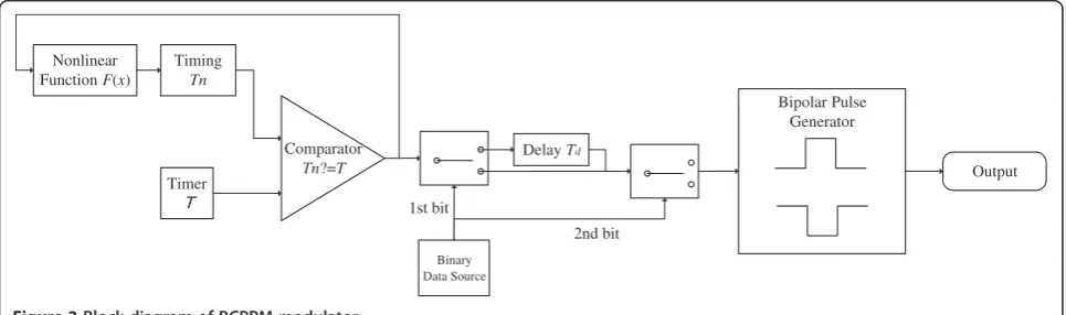
2.2 BCPPM modulator
BCPPM is based on the CPRG, and the modulator of BCPPM is shown in Figure 3. When the system initialization is complete, CPRG unit starts working: The nonlinear func-tion outputs the delay time valueTn; the timer starts timing; the comparator compares its two inputs constantly. When CPRG outputs the enable signal, the system reads the first bit data to decide whether to add theTdbefore entering later modules. After that, it reads the second bit data to choose the polarity of the narrow pulse for output.
In Figure 3, we can see that the sent data are grouped in every two bits. In each round, the first bit data and the chaotic map determine the position of pulse and the second bit determines its polarity. The delay module is moved outside of the feedback loop compared with that of CPPM. It makes the signal intervals of CPRG only relevant to the states of nonlinear function which is in-side the CPRG. They are independent of the information sequence. Here, we get Tn=F(Tn−1). In this way, it avoids the possible adverse effects of information se-quence to the chaotic map and keeps the no regularity of output pulse intervals sequence of CPRG. Besides, it eliminates the possibility of divergence. In each trans-mission period, the BCPPM modulator outputs a bipolar pulse, which contains two-bit information under the same conditions with CPPM. So, the BCPPM scheme doubles the information rate.
Nonlinear
Through the above analysis, the transmitted signal of BCPPM can be expressed as
U tð Þ ¼X
∞
j¼0
−1
ð Þb2jþ1ω t−t j
ð1Þ
whereω(t) is the baseband transmission signal.
tj¼t0þ
Xj−1
j¼0
Tnþb2jTd ð2Þ
wheret0is the initial delay for system.
bjis the data to be transmitted:
bj¼ 01 j¼1;2;⋯
ð3Þ
2.3 BCPPM demodulator
Pulse sequence with delay and polarity modulation be-comes the signal to be transmitted in the channel. If an unauthorized receiver does not know the interval infor-mation of pulse sequence, it is impossible to judge whether a received pulse was delayed. Therefore, it can-not judge whether ‘0’ or ‘1’ is transmitted at this mo-ment. If there is an ideal synchronization between the transmitter's CPRG and the receiver's CPRG, it will output the same signal with the sent signal in channel except some of the pulses delayed due to the data modulation. By estimating the received signal and the time when CPRG
outputted the corresponding pulse, the first bit data can be restored. On this basis, according to the polarity infor-mation of pulse, the second bit data can be judged. While the CPRGs of both sides of the transceiver are not enough to match, it will generate a large number of errors. There-fore, the initial parameters of CPRG act like a private key and play a decisive role in the transmission.
In the case of ideal synchronization between transmit-ter and receiver, the receiver will know the time or time window when the pulse is expected to appear. That al-lows the output of the receiver to be kept locked before the appearance of excepted pulses. During this period, other users can transmit their information pulses. In BCPPM, there are two time windows in the receiver. The BCPPM receiver is shown in Figure 4. Based on the synchronization of the transmitter and the receiver, the CPRG of the receiver enables the sampler near the time when the pulse is expected to appear. It will create a time window which contains the expected pulse, then divide the window into two parts based on the timeTd, time window ‘0’ and time window ‘1’, respectively. The signal in time window‘0’and time window‘1’are trans-ferred to a two-peak detector, then it figures out the two bits of information. The detailed demodulation process can be described as follows:
While demodulating the two-bit data, priority should be given to the first bit, then the second one. The first bit, delay information, can be judged from the sampling value in which window it has the larger peak. If the peak
Nonlinear Function F(x)
Timing
Tn
Timer
T
Comparator
Tn?=T
Pulse Generator Delay Td
0/1
Figure 2Block diagram of classical CPPM.
Nonlinear Function F(x)
Timing
Tn
Timer
T
Delay Td
Bipolar Pulse Generator
Output
Binary Data Source
1st bit
2nd bit Comparator
Tn?=T
is in window‘0’, the first bit is‘0’. Otherwise, it is‘1’. On this basis, the detector detecting the polarity of pulse in the above time window, if it is positive, the second bit information is‘0’. Otherwise, it is‘1’. So, there are a total of four cases for the two-bit data, as it is shown in Figure 5.
It is clear that the feedback loop in CPPM was re-moved in Figure 4. This eliminates the dependence of receiver CPRG synchronization on the accuracy of the demodulator judgment. It also eliminates the asynchron-ous problem between transmitter's CPRG and receiver's CPRG due to the wrong judgments, thus avoiding the error propagation. Thus, the BCPPM scheme greatly im-proves the practicability of the system.
2.4 Performance of BCPPM
Let x1= 1, denoting that the demodulation of the first bit is incorrect, and x1= 0, denoting that the demodula-tion of the first bit is correct. With the same notademodula-tion,
x2= 1, which means that the demodulation of the second bit is incorrect; while x2= 0, which means that the de-modulation of the second bit is correct. The first bit and the second bit are dependent in the demodulator of the BCPPM system. The judgment of the second bit de-pends on the time window which is decided by the first
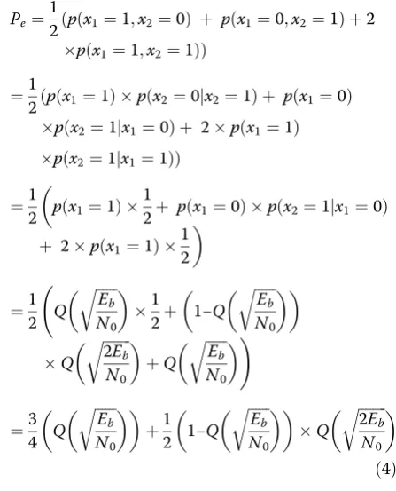
bit. So the output of the first bit will affect the judgment of the second bit. If the demodulation of first bit is in-correct, as a result, the second bit will not fall in the cor-responding time window. The sampling value of the signal is the noise level so the judgment is like coin tos-sing. In this case, the probability of correct demodula-tion for the second bit is 0.5. So, in the case of ideal timing, the BER of the BCPPM system is the following:
Pe¼
3 Cyclic LDPC codes of system
3.1 Cyclic LDPC codes
Cyclic codes and LDPC codes are all linear block codes, and some special cyclic codes are LDPC codes at the same time. This is the so-called cyclic LDPC. For ex-ample, a generator polynomial of (15, 7) cyclic LDPC is:
g(x) =x8+x7+x6+x4+ 1. According to the generator polynomial, we get the generator matrix G and check matrixHas follows:
Nonlinear
Figure 4Block diagram of BCPPM demodulator.
A
Having theGandHmatrices we can see that this cyc-lic code is also a LDPC code and irregular one.
In this paper, we design a (255,175) cyclic LDPC, whose generator polynomial is as follows:
g xð Þ ¼x80þx78þx76þx74þx71þx69þx68þx67
Since the G matrix satisfies the cyclic characteristics, we can use the feedback shift register to encode the (255,175) cyclic LDPC code at the transmitter, and use the LDPC decoding algorithm at the receiver. Thus, the design combines the hardware (such as FPGA) easy to implement of cyclic codes and low decode BER of LDPC codes. It can obtain high communication quality.
3.2 LDPC codes decoding algorithm
The Min-sum decoding algorithm is a simplified ap-proximate algorithm of the log domain belief propaga-tion (BP) decoding algorithm [14]. It uses minimum operation to simplify the function operation and to re-duce the computational complexity greatly. What is more, it does not need to estimate the channel noisy and has no complex operations. So it is easy for hardware implementation. But its performance is reduced when
compared with the BP decoding algorithm [15]. In gen-eral, the Min-sum decoding algorithm is very suitable to the occasion where one has limited hardware conditions. Here, the Min-sum decoding algorithm is used for the BCPPM communication system.
The Min-sum algorithm is as follows:
a) Initialization
c) Code word test
L qð Þ ¼i L Pð Þ þi maximum number of iterations, system will output the decoding results.
Then, return to step b.
4 Simulation and analysis
4.1 Additive white Gaussian noise channel
Firstly, we use the additive white Gaussian noise (AWGN) channel model to simulate the BER of BCPPM, CPPM, and CPOOK. We consider the first and second bits to-gether in the theoretical analysis and simulations, so the BER performance is the result of the whole BCPPM sys-tem. Simulation parameters are chosen as follows:
1) For simplicity, we use the one-dimensional logistic maps:
Tn¼anTn−1ð1−Tn−1Þ ð12Þ
wherean= 3.99,T0= 0.68;
0 1 2 3 4 5 6 7 8 9 10
10-5 10-4 10-3 10-2 10-1
Eb/No(dB)
BER Idea BCPPM
Idea CPPM Idea CPOOK
BCPPM CPPM
CPOOK BCPPM-LDPC CPPM-LDPC CPOOK-LDPC
Figure 6Simulation of additive Gauss white noise channel model.
0 1 2 3 4 5 6 7 8 9 10
10-4 10-3 10-2 10-1 100
Eb/No(dB)
BER
Multipath
BCPPM CPPM CPOOK
BCPPM-LDPC CPPM-LDPC CPOOK-LDPC
2) The (255,175) cyclic LDPC has been described in section3.2.We can figure out the system rate is3551 when using the LDPC code.
As shown in Figure 6, we get nine BER curves. They are the BCPPM, CPPM, and CPOOK systems in ideal condi-tion; the BCPPM, CPPM, and CPOOK system simulations without LDPC; and the BCPPM, CPPM, and CPOOK
simulations with LDPC. From the figure, we can see that the simulation results of BCPPM and CPOOK match the ideal curves well in the case of non-ideal timing because the structure of these systems can overcome the error propagation phenomenon. Furthermore, BCPPM has the lower BER compared with CPPM and CPOOK. Because each bit signal needs to transmit an extra synchronization pulse in CPOOK, the efficiency of the transmitter is
0 1 2 3 4 5 6 7 8 9 10
10-4 10-3 10-2 10-1 100
Eb/No(dB)
BER
Multiuser
BCPPM CPPM CPOOK
BCPPM-LDPC CPPM-LDPC CPOOK-LDPC
Figure 8Simulation of multiple-access model.
0 1 2 3 4 5 6 7 8 9 10
10-4 10-3 10-2 10-1 100
Eb/No(dB)
BER
Multipath & Multiuser
BCPPM
CPPM CPOOK BCPPM-LDPC CPPM-LDPC
CPOOK-LDPC
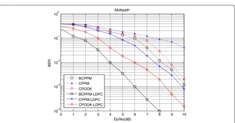
4.2 Multipath channel
Here, we simulate the multipath channel model for BCPPM, CPPM, and CPOOK. For simplicity, the channel model is a two-path channel. The simulation parameters are chosen as follows:
1) Gain of the path 1 isα1= 0.8 and path 2 isα2= 0.6;
2) The path delays areτ1= 0 andτ2= 2 respectively;
3) The rest are same with section4.1.
From the simulation results in Figure 7, we find that BCPPM has stronger multipath tolerance than CPPM and CPOOK. The reason is that the status information of chaotic system is completely contained in the time intervals of the pulses with the same shape. The distor-tion caused by the filter and the channel will only des-troy the shape of pulses, and not affect the intervals between them.
4.3 Multiuser model
In BCPPM, CPPM, and CPOOK, multiuser communica-tion means assigning different initial values to each user for the chaotic maps, as we have discussed in section 2.3. In this section, we simulate the multiuser model for BCPPM, CPPM, and CPOOK. For simplicity, there are two users in this model and the parameters are chosen as follows:
1) Initial value for the chaotic map of user 1 isxð Þ01 ¼0:68, the value of user 2 isxð Þ02 ¼0:78;
2) The rest are same with section4.1.
The simulation results are shown in Figure 8. The figure shows that though the BCPPM system multiple access mode is simple, it still has low BER performance when using the LDPC codes. That is because the synchronization of the CPRG is between the transmitter and the receiver. Every user's receiver will be kept locked outside its time windows. If the pulses of different users are outputs in dif-ferent time windows, there will be no multiuser interfer-ence from each other.
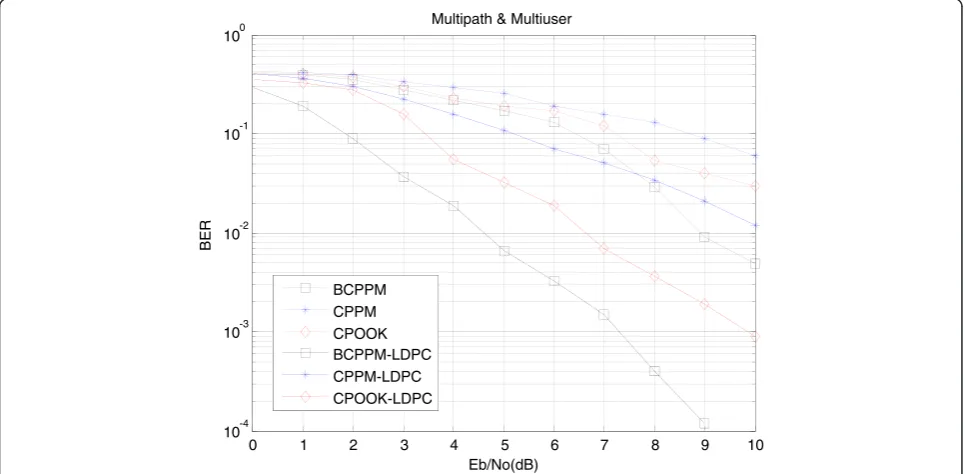
4.4 Multipath channel and multiuser model
Finally, we compare the performance of BCPPM, CPPM, and CPOOK in the multipath channel which has two users. The simulation parameters are same with those in section 4.2. and section 4.3.
From the simulation results, we get four BER curves as before, as shown in Figure 9. It shows that, considering complex communications background of the multipath
5 Conclusion
In this paper, we proposed a BCPPM communication sys-tem, described the structure of transmitter and receiver, and then discussed the possibility of combining cyclic LDPC code with the system. The BCPPM system has the advantage of high security, insensitivity to channel distor-tion and simplicity of deploying in multiuser communica-tion. The simulation results show that BCPPM system has a lower BER compared with the CPPM and CPOOK sys-tems. Besides, the use of cyclic LDPC codes is more con-ductive for the hardware implementation and has better BER performance.
Competing interests
The authors declare that they have no competing interests.
Acknowledgements
This work was supported by the National Natural Science Foundation of China (Grant No. U1304523), the Young Scientists Fund of the National Natural Science Foundation of China (Grant No. 11105042) and the Henan Provincial Department of Education Science and Technology Research key project (No.13A510330).
Author details
1School of Electrical Engineering and Automation, Henan Polytechnic
University, Jiaozuo 454000, China.2School of Engineering and Information Technology, Charles Darwin University, Darwin 0909, Australia.
Received: 4 December 2013 Accepted: 12 June 2014 Published: 22 June 2014
References
1. YS Shen, FB Ueng, LD Jeng, A new time-hopping/direct-sequence biorthogonal PPM UWB communication system. EURASIP J. Wirel. Commun. Netw. 149, 1–11 (2011)
2. LC Tran, A Mertins, TA Wysocki, Unitary differential space-time-frequency codes for MB-OFDM UWB wireless communications. IEEE Trans. Wirel. Commun.12(2), 862–876 (2013)
3. LS Jin, Y Zhang, LJ Li, One-to-many chaotic synchronization with application in wireless sensor network. IEEE Commun. Lett.17(9), 1782–1785 (2013) 4. H Yang, GP Jiang, Reference-modulated DCSK: a novel chaotic communication
scheme. IEEE Trans. Circuits Syst. II Expr. Briefs60(4), 232–236 (2013) 5. M Sushchik, N Rulkov, L Larson, L Tsimring, H Abarbanel, K Yao, A Volkovskii,
Chaotic pulse position modulation: a robust method of communication with chaos. IEEE Commun. Lett.4(4), 128–130 (2000)
6. N Rulkov, M Sushchik, L Tsimring, A Volkovskii, Digital communication using chaotic-pulse-position modulation. IEEE Trans. Circuits Syst. 12(48), 1436–1444 (2001)
7. H Torikai, T Saito, W Schwarz, Multiplex communication scheme based on synchronization via multiplex pulse-trains, inProceedings of the 1998 IEEE International Symposium on Circuits and Systems(Monterey, CA, USA, 1998), pp. 554–557
8. H Yang, GP Jiang, P Deng, Chaotic pulse On-off-keying modulation scheme for ultra-wide bandwidth communications. J. Electron. Inform. Technol. 29(3), 677–680 (2007)
9. H Yang, GP Jiang, A modified, chaotic pulse position modulation scheme for ultra-wide bandwidth communication. J. Nanjing Univ. Posts Telecommun. 26(2), 47–50 (2006)
10. RG Gallager, Low-density parity-check codes. IRE Trans. Inform. Theor.8(1), 21–28 (1962)
11. GH Zhang, R Sun, XM Wang, Several explicit constructions for (3, L) QC-LDPC codes with girth at least eight. IEEE Commun. Lett.17(9), 1822–1825 (2013) 12. B Rong, YY Wu, G Gagnon, Multi-layer iterative LDPC decoding for broadband
13. SX Li, SH Hu, T Feng, GN Ge, The weight distribution of a class of cyclic codes related to Hermitian forms graphs. IEEE Trans. Inf. Theory59(5), 3064–3067 (2013)
14. DJC Mackay, Good error-correcting codes based on very spares matrices. IEEE Trans. Inf. Theor.45, 399–431 (1999)
15. EB Li, D Declercq, K Gunnam, Trellis-based extended min-sum algorithm for non-binary LDPC codes and its hardware structure. IEEE Trans. Commun. 61(7), 2600–2611 (2013)
doi:10.1186/1687-1499-2014-105
Cite this article as:Liet al.:Bipolar chaotic pulse position modulation communication system based on cyclic LDPC.EURASIP Journal on Wireless Communications and Networking20142014:105.
Submit your manuscript to a
journal and benefi t from:
7Convenient online submission
7Rigorous peer review
7Immediate publication on acceptance
7Open access: articles freely available online
7High visibility within the fi eld
7Retaining the copyright to your article