R E S E A R C H
Open Access
A simplified hard output sphere decoder for
large MIMO systems with the use of efficient search
center and reduced domain neighborhood study
Youssef Nasser
1*, Sebastien Aubert
2,3, Fabienne Nouvel
3, Karim Y. Kabalan
1and Hassan A. Artail
1Abstract
Multiple-input multiple-output (MIMO) with a spatial-multiplexing (SM) scheme is a topic of high interest for the next generation of wireless communications systems. At the receiver, neighborhood studies (NS) and lattice reduction (LR)-aided techniques are common solutions in the literature to approach the optimal and computationally complex maximum likelihood (ML) detection. However, the NS and LR solutions might not offer optimal performance for large dimensional systems, such as large number of antennas, and high-order constellations when they are considered separately. In this paper, we propose a novel equivalent metric dealing with the association of these solutions by introducing a reduced domain neighborhood study. We show that the proposed metric presents a relevant complexity reduction while maintaining near-ML performance. Moreover, the corresponding computational complexity is shown to be independent of the constellation size, but it is quadratic in the number of transmit antennas. For instance, for a 4 × 4 MIMO system with 16-QAM modulation on each layer, the proposed solution is simultaneously near-ML with perfect and real channel estimation and ten times less complex than the classical neighborhood-basedK-best solution.
1 Introduction
Multiple-input multiple-output (MIMO) technology has taken a lot of attention in the last decade since it can improve link reliability without sacrificing bandwidth efficiency or, contrariwise, it can improve the bandwidth efficiency without losing link reliability [1]. Recently, the concept of large MIMO systems, i.e., high number of antennas, has also gained research interests, and it is well seen as a part of next-generation wireless communi-cation systems [2, 3].
However, the main drawback of MIMO technology is the increased complexity at the receiver side when a non-orthogonal (NO) MIMO scheme with a large num-ber of antennas and/or large constellation size is imple-mented [4, 5]. For the detection process, although the performance of the maximum likelihood (ML) detector is optimal, its computational complexity increases exponen-tially with the number of transmit antennas and with the constellation size. In literature, different MIMO detection techniques have been proposed. The linear-like detection
(LD) [6] and decision-feedback detection (DFD) [7] are the baseline detection algorithms. Here, we distinguish the conventional linear MIMO detection techniques zero forcing (ZF) [8] and minimum mean square error (MMSE) [8]. Although linear detection approaches are attractive in terms of their computational complexity, they might lead to a non-negligible degradation in terms of performance [9].
Some non-linear detectors have been also introduced. The sphere decoder (SD), one of the most famous MIMO detectors, is based on a tree search and is very popular due to its quasi-optimal performance [10]. However, this performance is reached at the detriment of an additional implementation complexity. Indeed, the SD achieves quasi-ML performance while its aver-age complexity is shown to be polynomial (roughly cubic) in constellation size and in the number of transmit antennas over a certain range of signal-to-noise ratio (SNR) while the worst case complexity is still exponential [11]. From a hardware implementation point of view, the SD algorithm presents two main drawbacks. Firstly, its complexity coefficients can become large when the problem dimension is high, i.e., at the high spectral efficiency, high number of antennas, and high number of * Correspondence:[email protected]
1ECE Department, American University of Beirut, Bliss Street, Beirut, Lebanon
Full list of author information is available at the end of the article
users in multi-user MIMO (MU-MIMO) context. Sec-ondly, the variance of its computation time can be also large leading to undesirable highly variable decoding de-lays. Despite classical optimizations such as the Schnorr-Euchner (SE) enumeration [12], the SD originally pre-sented in [11] offers by nature a sequential tree search phase, which is an additional drawback for implementa-tion. In order to deal with these two aspects, the authors in [13] have proposed a sub-optimal solution denoted as theK-best [13, 14], whereKis the number of stored neigh-bors given a layer. However, even with a fixed computa-tional complexity and a parallel nature of implementation, some optimizations are required especially for high-order constellation and large number of antennas (due to the largeKrequired in this case) [15–18]. Aiming at reducing the neighborhood size (namelyK, over all layers), different solutions are proposed. For instance, the sorted QR decom-position (SQRD)-based dynamicK-best which leads to the famous SQRD-based fixed throughput SD (FTSD) is proposed in [16]. Even with these efforts, the neighbor-hood size still induces a computationally expensive solution for achieving quasi-ML performance. An al-ternative trend has been firstly presented in the litera-ture by Wuebben et al. in [19]. It consists in adding a pre-processing step, namely the lattice reduction (LR), aiming at applying a classical detection through a better-conditioned channel matrix [19–21]. This solution has been shown to offer the full reception diversity at the expense of a SNR offset in the system performance. This offset increases with large dimensional transmit antenna systems and high-order modulations.
Recently, a promising—although complex—association of the K-best and LR solutions has been considered. It provides a convenient performance-complexity tradeoff. The general idea consists in reducing the SNR offset through a neighborhood study which yields a near-ML performance for a reasonable K. The concept has been introduced first by the authors of [22]. Later on, their basic solution has been improved by proposing to model the sphere constraint in a reduced domain or by intro-ducing efficient symbols’ enumeration algorithm [23]. However, a major aspect of this combination has not been considered yet. In particular, any SD, including theK-best, may be advantageously applied by considering a better-conditioned channel matrix through the introduction of a Reduced Domain Neighborhood (RDN) study and a judicious search center. In [5], an improved LR technique dealing with the RDN has been proposed in the context of large MIMO systems. It is based on the decomposition of the spanned space of the channel matrix into small sub-spaces in order to improve orthogonality of the quan-tization. In [24], the search center is found through an ant colony optimization and initial search through the output of the MMSE detector.
In this paper, we adopt the K-best solution with fixed complexity as the basic solution of the SD. We propose to reduce the neighborhood size through an efficient pre-processing step which allows the SD process to apply a neighborhood study in a modified constellation domain. Then, using the modified domain, we propose a modified novel ML equation with an efficient search center. We show that the proposed metric presents a large complexity reduction while maintaining near-ML performance. More-over, the corresponding complexity is shown to be inde-pendent of the constellation size and polynomial in the number of transmit antennas. In particular, for a 4 × 4 MIMO system with 16-QAM modulation on each layer, the proposed association presents near-ML performance while it is ten times less complex than the classical K-best solu-tion. We note that because the complexity is fixed with such a detector, the exposed optimizations guarantee a perform-ance gain for a given neighborhood size or a reduction of the neighborhood size for a given bit error rate (BER) target. The contributions of this paper are summarized as follows:1
A promising association of theK-best and LR solutions is proposed.
Modification of the SD neighborhood study by applying a pre-processing step. This is accompanied with a new and efficient search center and MMSE detector. The equivalent expression of the lattice reduction-aided (LRA)-MMSE-centered SD, which corresponds to an efficient LRA-MMSE-successive interference canceller (SIC) Babai point, is proposed to improve the performance or reduce the complexity of the detector.
The (S)QRD is introduced in formulas. It provides—to the best of the authors’
knowledge—the best known pseudo-linear hard detector as a Babai point, for large number of antennas as well as for high-order modulations.
The proposed expression is robust by nature to any search center and constellation order and offers close-to-optimal performance with medium Kvalues. This applies for both perfect and real channel estimation.
The proposed solution offers a computational complexity that is independent of the constellation order. Therefore, it outperforms classical SD techniques for a reasonable complexity in the case of high-order constellations. We show for example that a number of neighborsK= 2 is sufficient for a 4 × 4 MIMO system with 16-QAM modulation on each layer, and it is less than 0.5 dB for a 64 × 64 and 128 × 128 MIMO system from the ML solution.
This paper is organized as follows. Section 2 pre-sents the problem statement of the SD. In Section 3, the different existing solutions are described and ana-lyzed. In Section 4, we propose our generalized solu-tion based on LR with the use of an efficient search center and reduced domain neighborhood. In Section 5, the performance of the presented detectors are provided, compared, and discussed. In Section 6, we consider the computational complexity of the proposed solution in comparison with some reference detection techniques. Conclusions are drawn in Section 7.
2 Problem statement
2.1 Sphere decoder detector
Let us introduce anR×nTMIMO system model withnT
transmit and nR receive antennas. Then, the received
symbols vector could be written as
y¼Hxþn; ð1Þ
whereHrepresents the (nR,nT) complex channel matrix
assumed to be perfectly known at the receiver, x is the transmit symbol vector of dimensions (nT, 1) where each
entry is independently withdrawn from a constellation set ξ, and n is the additive white Gaussian noise of dimensions (nR, 1) and of variance σ2/2 per dimension.
The basic idea of the SD, to reach the optimal estimate ^
xML (given by the ML detector) while avoiding an exhaustive search, is to observe the lattice points that lie inside a sphere of radiusd.
The SD solution starts from the ML equation x^ML¼ argminx∈ξnT∥y−Hx∥2 and reads
whereH=QR, with the classical QRD definitions. The classical SD formula in (2) is centered on the received signal y. From now on, this detection will be denoted as the naïve SD. In the case of a depth-first search algorithm [13], the first solution given by this algorithm is defined as the Babai point [25, 26]. In order to write it, the classical SD expression may be re-arranged, leading then to an exact formulation through an efficient partial Euclidean distance (PED) expression and early pruned nodes [27].
In the literature, the SD principle leads to numerous implementation problems. In particular, it is a non-deterministic polynomial-time (NP-hard) problem [28]. This aspect has been partially solved through the introduction of an efficient solution that lies in a fixed neighborhood size algorithm (FNSA), commonly known as the K-best solution. However, this solution makes the detector sub-optimal since it leads to a performance loss compared to the ML detector. It is
particularly true in the case of an inappropriate choice of K according to the MIMO channel condition num-ber and in the case of an inappropriate choice of d in (2). Indeed, an inappropriate choice ofdcould lead to a ML solution excluded from the search tree. On the other hand, although a neighborhood study remains the one and only one solution that achieves near-ML performance, it may lead to the use of a large-size neighborhood scan which would correspond to a dramatic increase of the computational complexity. This complexity’s increase will be prohibitive for high-order modulations.
2.2 Lattice reduction
Through the aforementioned considerations and by using the lattice definition in [26], the system model given in (1) rewrites
y¼H z~ þn; ð3Þ
where H~ ¼HT and z=T−1x. The nT×nT complex
matrix T (with |det{T}| = 1) is unimodular, i.e., its en-tries belong to the set of complex integers which reads
ℤℂ=ℤ+jℤ, with j2= 1. The key idea of any LR-aided (LRA) detection scheme is to understand that the finite set of transmitted symbols ξnTcan be interpreted as a de-normalized, shifted then scaled version of the infinite set of complex integers subset ⊂ℤnT
ℂ according to the relations offered in [29].
This issue is expected to be bypassed through an additional neighborhood study.
2.3 Lattice reduction-aided sphere decoder
Contrary to the LRA-(O)SIC receivers, the application of the LR preprocessing step followed by any SD detector is not straightforward. The main problem lies in the consideration of the possibly transmit symbol vector in the reduced constellation since, unfortunately, the set of all possible transmit symbols vectors cannot be predeter-mined. The reason for that is because the solution does not only depend on the employed constellation but also on theT−1matrix of (3). Hence, the number of children in the search tree and their values are not known in advance. A brute-force solution is then to determine the set of all possible transmit vectors in the reduced con-stellation, starting from the set of all possible transmit vectors in the original constellation and by switching to the reduced domain, thanks to theT−1matrix.
3 Detection process in the original domain neighborhood
3.1 Zero forcing-centered sphere decoder with original domain neighborhood study detection process
In order to deal with the detection process, we firstly introduce the sphere center xC search algorithm. It
concerns any signal of the form ∥xC−x∥2≤d2wherex
is a possible signal.
Based on this search algorithm, different possible sphere centers could be introduced. Using a ZF detector, the received symbols given in (2) are then estimated through
^
xZF‐SIC¼argmin x∈ξnT
∥ReZF∥2 ð4Þ
whereeZF=xZF−xand xZF= (HHH)−1HHy.
Equation (4) clearly shows that the naïve SD is un-constrained ZF-centered. It implicitly corresponds to a ZF-SIC solution with an Original Domain Neigh-borhood (ODN) study at each layer where each layer is defined as the number of spatial multiplexed data streams. It can be noticed that, in the case of a large ODN study, the ML performance is achieved since the computed metrics are exactly the ML metrics. However, this occurs at the detriment of a large neighborhood study and subsequently a large com-putational complexity.
3.2 Minimum mean square error-centered sphere decoder with original domain neighborhood study detection process: equivalent formula
In this section, we introduce the minimum mean square error successive interference cancellation (MMSE-SIC), a closer-to-ML Babai point than the ZF-SIC. For the sake of
clearness with definitions, we firstly give a general defin-ition of the equivalence between two ML metrics.
Definition Two ML equations are equivalent if the lattice point argument outputs of the minimum distance are the same, even in the case of different metrics. Two ML equations are equivalent iff:
argmin
wherecis a constant.
Using (5), Cui et al. [36] proposed a general equivalent minimization problem given by
where the signalsx have to be of constant modulus, i.e., xHxis a constant.
This assumption is respected in the case of quadrature phase-shift keying (QPSK) modulations, but it is not directly applicable to 16-QAM and 64-QAM modula-tions. However, this assumption is not limiting in prac-tice since a QAM constellation can be considered as a linear sum of QPSK points [36]. In Appendix 1, we discuss the constant modulus constraint on the signalx.
The authors of [37] proposed to apply this solution to the FNSA detection technique of the unconstrained MMSE center, leading to a MMSE-SIC procedure with an ODN study at each layer [37]. In this case, the equivalent ML equation reads
Through the use of the Cholesky factorization (CF) of HHH+σ2I
=UHU in the MMSE case (HHH=UHU in the ZF case), the ML expression equivalently rewrites, using the proof in Appendix 2, as
^
where U is upper triangular with real diagonal ele-ments and ~x is any (ZF or MMSE) unconstrained lin-ear estimate.
4 Proposed detection process in the reduced domain neighborhood
LR step followed by a neighborhood study is a very inter-esting solution in a good-conditioned channel matrix. Accordingly, our proposed combined solution will be detailed in the next subsections.
4.1 Preprocessing
All existing solutions rely on the utilization of the efficient CF pre-processing step. However, these solutions are only functional in the case of a factorized formulation form. Al-though it is the case in our context, most of the advanced studies have been provided with the applicable QRD. In particular, the advantageous SIC performance optimiza-tions such as ordering according to the corresponding de-creasing SNR (from nT to 1) in the ZF-SQRD case and
SINR in the MMSE-SQRD case have been proposed in [33]. Moreover, a complexity reduction of the LLL-based LR algorithm has been proposed by the same authors in [33]. In our work, we propose to modify the classical detectors by introducing the QRD instead of the CF, and subsequently of the SQRD, in the (LRA-)MMSE-(O)SIC cases.
The MMSE criterion is introduced through the consideration of an extended system model [27], by introducing the (nR+
nT)‐by‐nTmatrixHextand the (nR+nT) vectoryextsuch as
Hext¼ σHI
andyext¼ y0 : ð9Þ
In this way, the pre-processing step is similar to the ZF-SQRD and the detection procedure equals that of LRA-ZF-SIC. The SQRD interest lies in the ordering of the detection symbols as a function of their S(I)NR, and consequently, it limits the error propagation in SIC procedures. Indeed, it has been shown by Wübben et al.
[19] that the optimum order offers a performance im-provement even if the ML diversity is not reached. On the other hand, it was shown that once the ML diversity is achieved through a LRA technique, the performance may be significantly improved with this solution [19]. Thus, The LRA-MMSE-OSIC corresponds, to the best of the authors’ knowledge, to the best pseudo-linear detector proposed in the literature, in particular in the case of 4 × 4 MIMO systems with QPSK modulations on each layer [19]. For higher order constellations or larger number of antennas, it may be shown that our proposed solution of-fers convenient hard-decision performance with a highly reduced complexity. In order to deal with these state-ments, we introduce the reduced domain neighborhood by using the following notations:
QξnTf g: is the quantification operator in the original
domain constellation,
QℤnT
ℂ f g: is the quantification operator in the reduced
domain constellation,
ais the power normalization and scaling coefficient (i.e., 2=pffiffiffi2; 2=p10ffiffiffiffiffi; and 2=pffiffiffiffiffi42for QPSK, 16-QAM, and 64-QAM constellations, respectively)
d¼12T−1½1þj … 1þjT is a complex displacement vector.
The classical LRA-FNSA is implicitly unconstrained LRA-ZF-centered, which leads to a LRA-ZF-SIC proced-ure with a RDN study at each layer. The exact formula has not been clearly provided but is implicitly used by any LRA-FNSA [21] and may even be considered as an incre-mental extension of (4):
^
zLRA‐ZF‐SIC¼argmin z∈ℤnT
ℂ
∥Re~ LRA‐ZF∥2 ð10Þ
whereR~ is the LLL-based LR algorithm output,eLRA‐ZF=
zLRA‐ZF−z, and ℤnTℂ is thenT-dimensional infinite set of
complex integers.
4.2 Lattice reduction-aided minimum mean square error-centered sphere decoder with reduced domain neighborhood study detection process
To the best of the author’s knowledge, no convincing formula has been proposed until now. Even if Jalden et al. [38] proposed a LRA-MMSE-centered solution, the introduced metrics are not equivalent to the ML expres-sion. The solution of [38] is given by
^
zα; ML¼argmin z∈ℤnT
ℂ
∥R~−1R−1†H†y−z∥2
¼argmin
z∈ℤnT
ℂ
∥zLRA‐MMSE−z∥2 ð11Þ
The corresponding detector is a sub-optimal solution that consists in a RDN study around the unconstrained LRA-MMSE solution, obtained through QR decom-position. This solution’s output is the constrained LRA-MMSE detection plus a list of solutions in the neighborhood. The latter is generated according to a non-equivalent metric, which would be subsequently re-ordered according to the exact ML metric. However, the list is not generated according to the correct distance minimization criterion and would not lead to a near-ML solution. Consequently, the proposed detector does not offer an acceptable uncoded BER performance in the sense that it would not lead to a near-ML solution. In particular, the ML performance is not reached in the case of a large neighborhood study.
An efficient solution is derived from (11) and consists in an unconstrained LRA-MMSE center which leads to a
LRA-MMSE-SIC procedure with a RDN study at each layer. The equivalent ML equation reads
^
zLRA‐SIC¼argmin z∈ℤnT
ℂ
∥U~ð~z−zÞ∥2; ð12Þ
where H~HH~ þσ2THT¼U~HU~ in the MMSE case (H~H ~
H ¼U~HU~ in the ZF case) and by noting thatŨis upper
triangular with real diagonal elements andz~ is any LRA (ZF or MMSE) unconstrained linear estimate. The proof of this detector formula is given in Appendix 3.
The formula introduced in (12) offers an equivalent metric to the MMSE one introduced in (11), which has been shown to be near-ML performance. The difference, and in particular the interest in the LRA case in (12), relies on the neighborhood study nature. In the case of a RDN study, the equivalent channel matrix H~ is consid-ered and is remembconsid-ered to be only roughly, and not exactly, orthogonal. Consequently, the detection, layer by layer, of the symbol vectorx does not exactly corres-pond to its joint detection since the mutual influence of the transformed zsignal is still present. This discussion not only exhibits the interest of SD-like techniques to still improve such a detector performance but also puts a big challenge to achieve the ML performance.
The general principle of RDN LRA-MMSE-OSIC-centered solution key points is depicted as a block dia-gram in Fig. 1. The detailed block diadia-gram description of the proposed solution is addressed in Fig. 2.
Fig. 3Block diagram of the RDN LRA-MMSE-OSIC FNSA
Table 1ODN naïve (O)SIC FNSA, ODN ZF-(O)SIC FNSA, ODN MMSE-(O)SIC FNSA, RDN LRA-ZF-(O)SIC FNSA, RDN LRA-MMSE-(O)SIC FNSA, and ML formulas
Technique designation Corresponding metric
ODN naïve (O)SIC FNSA ∥QHy−Rx∥2;x∈ξnT
ODN exact ZF-(O)SIC FNSA ∥R yðZF−xÞ∥2;x∈ξnT[14]
ODN equivalent MMSE-(O)SIC FNSA ðyMMSE−xÞHHHHþσ2IðyMMSE−xÞ; x∈ξnT[38]
RDN exact LRA-ZF-(O)SIC FNSA ∥R z~ð LRA‐ZF−zÞ∥2;z∈ℤnT
ℂ
RDN equivalent LRA-MMSE-(O)SIC FNSA (proposed) ðzLRA‐MMSE−zÞHH~HH~þσ2THTðzLRA‐MMSE−zÞ;z∈ℤnT
ℂ
In Fig. 2, the mapping of any estimate (or list of estimates) from the reduced domainẑto the original domainx~˜is proc-essed through theTmatrix multiplication (see Equation (3)). The additional quantification step aims at removing duplicate symbol vector outputs in the case of a list of solutions.
For the sake of simplicity, let us consider any LRA-SIC procedure with no neighborhood study. The search center is updated at each layer as follows. By considering the k-th layer and with the knowledge of the ^zkþ1:nT estimates at previous layers, theẑkunconstrained Babai point can be pro-vided. Then, it has to be de-normalized and shifted to make it belong to ℤnTℂ . After quantization, and de-shifting and normalization, the ẑk estimate at thek-th layer is obtained
such as the next (k−1)-th layer can be considered, until the
whole symbol vector is detected. As previously introduced, the neighborhood generation is a problematic step due to the infiniteness and non-regular natures of the constellations in the reduced domain. This point is transparent with classical detectors such as LD and DFD, thanks to the straight-forward quantification step in the reduced domain [39].
However, the issue of infinite lattices, addressed through a sphere constraint, appears when working with the classical considerations. It presents a performance loss or a NP-hard complexity solution. Hence, our proposed solution relies on a SE enumeration. Starting from the LRA-SIC principle, a neighborhood is considered at each layer and leads to the RDN LRA-SIC FNSA principle. In particular and due to the implementation
constraints, the RDN generation is processed for bounded number ofNpossibilities and in a SE fashion, namely with ordered PEDs according to an increasing distance from ~
zk at each layer as follows: zk¼QℤnT
ℂ f gz~k ; QℤnTℂ f g þ~zk 1; QℤnTℂ f g~zk þj; QℤnT
ℂ f g~zk ; QℤnTℂ f g~zk −1; QℤnTℂ f g~zk −j; … ð13Þ
The SE strategy aims at finding the correct decision early, leading to a safe early termination criterion, which is not considered here for the sake of readability in performance
comparison. Also, all the corresponding PEDs are com-puted and then ordered. TheK-best solutions, namely with the lowest PED, in the reduced domain are stored (Cẑ)
simi-larly to their corresponding cumulative Euclidean distances (CED) (Dtot). The whole procedure is depicted in Fig. 2.
By adding the pre-processing steps, i.e., the SQRD-based then LLL-SQRD-based LR blocks, and the computation of a close-to-ML unconstrained estimate (although linear) such as LRA-MMSE extended, a complete de-scription of the detection may be obtained. Figure 3 shows the detailed block diagram of the complete pro-posed solution. The SQRD block offers an efficient layer
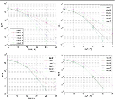
Fig. 5Uncoded BER of the ODN ZF-SIC-centered FNSA (curve 1), of the ODN MMSE-SIC-centered FNSA (curve 2), of the RDN LRA-ZF-SIC-centered FNSA (curve 3), of the RDN LRA-MMSE-SIC-centered FNSA (curve 4), of the RDN LRA-MMSE-OSIC-centered FNSA (curve 5), and of the ML (curve 6), for
re-ordering [19] that lies on the noise power. The latter is taken into account in the rest of the detector through theTmatrix.
As a final step of the detector and in the case of a RDN-based SD, the list of possible symbols output has to be re-ordered according to the ML metrics in the original domain and duplicate solutions are removed. It is due to the presence of noise that makes some candidates to be mapped on non-legitimate constellation points in the reduced constellation, leading to non-acceptable points in the original constellation. The symbol vector associated to the minimal metric becomes the hard decision output of the detector and offers a near-ML solution. The proposed algorithm is described
in detail in Appendix 4. The reader may refer to this appendix for more details.
5 System performance
In this section, we present and compare the system performance of the different techniques previously presented, and we compare them with our proposed solution. For clearness target, we summarize the detec-tion metrics for each soludetec-tion in Table 1.
We should note that the RDN LRA-MMSE-OSIC FNSA, to which this paper relates, is particularly efficient in the case of rank-deficient MIMO systems, i.e., spatially correlated antenna systems, for high-order modulation which are considered points of the LTE-A norm and for
Fig. 6Uncoded BER of the strictly equivalent ODN MMSE-SIC-centered FNSA, of the strictly equivalent RDN LRA-MMSE-SIC-centered FNSA, of the strictly equivalent RDN LRA-MMSE-OSIC-centered FNSA, compared to the assumption respect in mean, and of the ML, forK= {2, 4}, 4 × 4 complex Rayleigh channel, 16-QAM modulation on each layer.Some curves are coincident
large number of antennas as in the future generation of cellular systems (beyond 4G networks). Moreover, since the equivalent channel matrix in the LRA case is only roughly orthogonal, the mutual influence of the trans-formedzis small but still present. Hence, a neighborhood study in the original constellation domain improves the performance compared to a SIC. However, contrarily to classical solutions that are not LRA, the necessary size for achieving the optimal performance is smaller.
Figure 4 depicts the BER for the aforementioned tech-niques. Some notable points have to be highlighted from this figure. Contrary to the RDN LRA-ZF/MMSE-(O)SIC FNSA, the ODN ZF/MMSE-SIC FNSA does not reach the ML diversity for a reasonable neighborhood size, even if there is a decrease of the SNR offset in the MMSE-SIC
case. However, a BER offset can be observed in the low SNR range, due to error propagation. Consequently, there exists a switching point from low to high SNR between LRA detectors and others. This aspect is removed through the use of better techniques. In particular, the SQRD in the RDN LRA-MMSE-OSIC FNSA presented in this work offers ML diversity, and the BER offset in low SNR has been highly reduced compared to the RDN LRA-MMSE-SIC FNSA and is now close-to-ML.
It may also be noticed in Fig. 4 that the RDN LRA-ZF-SIC-centered FNSA does not reach the ML perform-ance, contrarily to other techniques. It is due to the chosen neighborhood size in the reduced constellation value (N= 5) that is not sufficient for this detector but that is sufficient for the proposed LRA-MMSE-(O)SIC
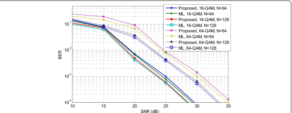
Fig. 8BER comparison between the proposed RDN LRA-MMSE-OSIC and ML detector, fornR=nT=N, 16-QAM (continuous line), 64-QAM (dash)
Fig. 9Uncoded BER with imperfect channel estimation, of the ODN MMSE-SIC-centered FNSA (FNSA curve), of the proposed RDN LRA-MMSE-OSIC-centered FNSA (proposed), and of the ML, with perfect channel estimationΔ= 0 and real channel estimation,Δ= 0.001 (left) and
Babai points. With a largerN value, the RDN LRA-ZF-SIC-centered FNSA achieves the ML performance, similarly to other presented detectors.
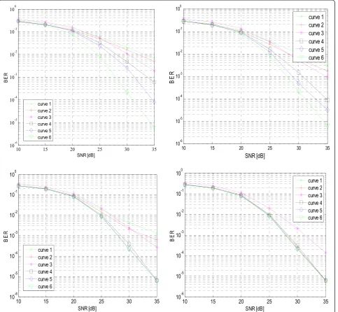
Similarly to Fig. 4, some notable points have to be highlighted from Fig. 5. There still exists a switching point from low to high SNR regime between LRA detectors and others. This aspect is removed through the use of better techniques. In particular, the SQRD in the RDN LRA-MMSE-OSIC FNSA offers ML diversity and the BER offset in low SNR has been importantly reduced compared to the RDN LRA-MMSE-SIC FNSA, leading now to a close-to-ML solution. We can observe from both Figs. 4 and 5 that even though when ZF-SIC and equivalent MMSE-SIC are not LRA, they achieve the ML performance at the detri-ment of a very large neighborhood study size; it is of the order of the number of symbols contained in the employed constellation. By comparing the impact on LRA detector performance of QPSK and 16-QAM modulations, two fundamental points must be discussed. Firstly, there impli-citly exists a constraint from the QPSK constellation con-struction that eliminates nearby lattice points that do not belong to ξnT, due to the quantization operation QξnTf g: . This aspect annihilates a large part of the LR-aid benefit and cannot be corrected despite the increase of the neigh-borhood study size since many lattice points considered in the RDN would be associated with the same constellation
point after quantization in the original constellation. In the case of larger constellation orders, the LRA solution is more effective, as depicted in Fig. 5.
Secondly, we recall that the constant modulus constella-tion assumpconstella-tion has, in theory, to be fulfilled. It was not the case in Fig. 5 with 16-QAM modulation on each layer. However, it could be assumed that this constraint would be almost respected in mean value as shown in Appendix 1 (Fig. 12). In Fig. 6, the performance of R(O)DN (LRA)-MMSE-(O)SIC FNSA detectors with or without respect of this assumption are depicted, but only for a neighborhood scan of 1 and 2 neighbors for the sake of consistency between QPSK and 16-QAM performance.
As depicted in Fig. 6 and with 16-QAM modulation, the performance is impacted by the fact that the strict equivalence assumption is not true, i.e., the termxHx(or zHz) is not exactly constant but only constant in average.
As shown in this figure, this assumption is not con-straining in terms of performance loss. Moreover, it is insignificant compared to the advantage of the LRA in high-order constellation, which would be annihilated by the use of QPSK constellation.
The proposed solution is particularly efficient for a large number of antennas and for high-order constellations. It was not the case of the LRA-MMSE-OSIC that has been shown worse BER performance in 4 × 4 MIMO systems with a 16-QAM modulation on each layer, compared to the ML detection [40], while it was the case for 4 × 4 MIMO systems with QPSK modulation on each layer [41]. For the sake of completeness of this work, Fig. 7 shows the same results with 64-QAM modulation as those given in Fig. 5. Again this figure shows the outperform-ance of the proposed detection algorithm with high-order constellation.
Figure 8 shows the comparison between the proposed RDN LRA-MMSE-OSIC-centered FNSA and the ML detection for high number of antennas, such thatnR=
nT=N= 64 and N= 128 and, K= 2. First, there is no
doubt that increasing the number of antennas increases the performance gain. Secondly, the proposed solution shows a comparable performance with respect to the ML decoder. At a BER = 10−4, the SNR loss is less than 0.4 dB
Table 2Computational complexity equivalences
Complex operations Real operations MUL
ADDCC 2ADD 0
Table 3ODN ZF-(O)SIC FNSA, ODN MMSE-(O)SIC FNSA, RDN LRA-ZF-(O)SIC FNSA, RDN LRA-MMSE-(O)SIC FNSA, and ML formulas
Technique designation Corresponding computational complexity in MUL
ODN exact ZF-(O)SIC 2MKn2
Tþ2MKnT−4MKþ3M
ODN equivalent MMSE-(O)SIC 2MKn2
for 16-QAM and less than 0.5 dB for 64-QAM while the complexity of the proposed RDN LRA-MMSE-OSIC-centered FNSA solution is by far much lower than the ML decoder. This will be discussed in the next section.
Finally, even though it is not the target of the paper, we have drawn the simulation results of the proposed solution with real channel estimation. Figure 9 shows the simulation results when the channel estimation error variance Δ is equal to 0.001 and 0.005, assuming that the channel coefficients power is normalized by the number of antennas. This figure shows that the pro-posed LRA-MMSE solution still presents quasi-ML detection even with real channel estimation.
6 Complexity evaluation
Based on the assumptions presented in Table 1, the com-putational complexities introduced in Table 2 can be dem-onstrated. The RDN study is processed in an infinite lattice which would not lead to boundary control; however, a finite set of displacements has been generated in a SE fashion in simulations. Its size has been fixed to an arbitrary value (N= 5)—decided through simulations. Although an SE technique is used, the proposed solution does not consider any complexity reduction like early termination.
As shown in Table 3, the computational complexities of RDN LRA-ZF/MMSE-(O)SIC FNSA detectors do not depend on the constellation order log2{M}. It may be
checked in the numerical applications in Table 4, and it is the key point of the paper advantage over classical techniques for high-order modulations such as
16(64)-QAM. The SNR loss compared to ML are given in Table 4. They have been measured for an uncoded BER of 10−4in the case of the ML decoder. For all the config-urations given in Table 4, the numerical application of the corresponding computational complexity is given in Table 5 for a RDN sizeN= 5.
Even if the proposed solution is two times more com-plex in the QPSK case, it offers near-ML performance and in particular a SNR gain of 0.3 dB at a BER of 10−4. The interesting point concerns higher order modulations: starting from the 16-QAM modulation, the estimated complexity of the proposed solution is ten times less com-plex than the classical one, for the same performance result. Identically, same conclusions are obtained for a 64-QAM modulation. In such case, the complexity gain will increase importantly to reach a hundred times. Similarly, the numerical application of the 16-QAM extension com-plexity is given in Table 6. As an example, in the case of 16-QAM modulations, the computational complexities read 8MKn2Tþ4MKnT−4MKþ3M for the ODN MMSE-(O)SIC, and withM= 4 since a QPSK modulation is considered in this case. As depicted in Table 6, the computational complexity of the 16-QAM extension with respect to the constant modulus criterion is more import-ant compared to the straightforward but not strictly correct solution. Since no significant gain is provided, we consequently claim it does not offer high advantages.
Table 4SNR loss at BER = 10−4, ODN ZF-SIC FNSA, ODN MMSE-SIC FNSA, RDN LRA-ZF-SIC FNSA, RDN LRA-MMSE-SIC FNSA, and RDN LRA-MMSE-OSIC FNSA compared to ML
SNR loss (QPSK) SNR loss (16-QAM)
Technique K = 1 K = 2 K = 3 K = 4 K = 1 K = 2 K = 4 K = 16
ODN exact ZF-SIC FNSA >7.6 >7.6 >7.6 0.36 >5.0 >5.0 >5.0 0
ODN equivalent MMSE-SIC FNSA >7.6 >7.6 6.21 0.30 >5.0 >5.0 >5.0 0.09
RDN exact LRA-ZF-SIC FNSA 4.43 2.90 1.92 1.71 3.21 2.04 1.27 0.62
RDN equivalent LRA-MMSE-SIC FNSA 2.90 0.73 0.52 0.27 2.12 0.76 0.53 0.40
RDN equivalent LRA-MMSE-OSIC FNSA 0.80 0.01 0 0 1.62 0.02 0 0
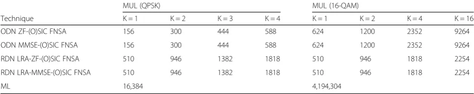
Table 5ODN ZF-SIC, ODN MMSE-SIC, RDN LRA-ZF-SIC, RDN LRA-MMSE-SIC, RDN LRA-MMSE-OSIC, and ML computational complexities in MUL
MUL (QPSK) MUL (16-QAM)
Technique K = 1 K = 2 K = 3 K = 4 K = 1 K = 2 K = 4 K = 16
ODN ZF-(O)SIC FNSA 156 300 444 588 624 1200 2352 9264
ODN MMSE-(O)SIC FNSA 156 300 444 588 624 1200 2352 9264
RDN LRA-ZF-(O)SIC FNSA 510 946 1382 1818 510 946 1818 2254
RDN LRA-MMSE-(O)SIC FNSA 510 946 1382 1818 510 946 1818 2254
Figure 10 shows the “measured” complexity of all solutions explored in this work versus the constellation size, expressed in terms of the exponent (in base 10) of the computational capacity in MUL, fornR=nT= 8 and
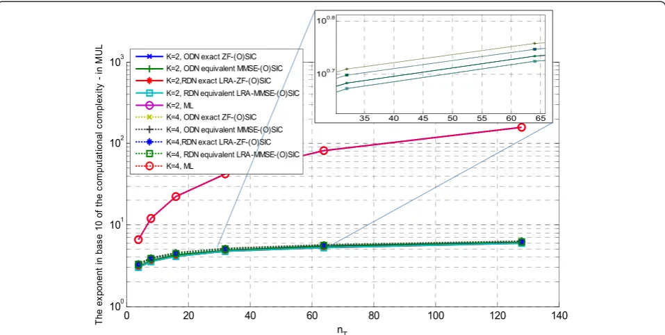
K= 2. This figure shows, as explained earlier, that the proposed solution is independent of the constellation size. This is very crucial in the future large MIMO systems exploiting large dimensions. Figure 11 is in line with the previous conclusion. It provides the computation complexity of the different MIMO detection solutions, expressed as a function of the number of antennas. This figure shows that the proposed solution is almost ten times less complex than the classicalK-best solutions. Moreover, it presents almost equal complexity for nT≥32 yielding
another important characteristic for large MIMO decoding. Finally, to give some concrete example, Table 6 compares between ODN and RDN cases. It shows that the proposed solution offers an advantage over existing solutions when applied to any OFDM standard supporting MIMO spatial-multiplexing mode, e.g., IEEE 802.16, IEEE 802.11, 3GPP LTE, and 3GPP LTE-A. It may be advantageously considered in the case of a large number of antennas and consequently in the case of the 3GPP LTE-A standard. The main advantages reside in the following points:
▪The equivalent expression of the LRA-MMSE-centered SD, which corresponds to an efficient
LRA-MMSE-OSIC Babai point, improves the performance or reduces the complexity of the detector.
▪The proposed (S)QRD formulation with reduced domain neighborhood induces the use of the best known hard detector as a Babai point, for both large number of antennas and high-order modulations.
▪The proposed expression is robust by nature to any search center and constellation order and offers close-to-optimal performance for largeK. Likewise, the proposed solution offers a computational complexity that is independent of the constellation order which consequently offers a solution that outperforms classical SD techniques for a reasonable computational complexity in the case of high-order constellations. For instance, the neighborhood study size K has been reduced to K= 2 for a 16-QAM modulation compared to classical SD techniques.
7 Conclusions
In this paper, the LRA-MMSE-centered SD has been proposed with a K-best neighborhood generation. A detailed and hardware implementation-oriented compu-tational complexity estimation has been provided and combined with performance results. It has been shown that the proposed detection technique outperforms the existing solutions. In particular, the corresponding
Table 6ODN MMSE-SIC, RDN LRA-MMSE-SIC, and RDN LRA-MMSE-OSIC computational complexities in MUL
MUL (16-QAM extension) MUL (16-QAM)
Technique K= 1 K= 2 K= 3 K= 4 K= 1 K= 2 K= 4 K= 16
ODN equivalent MMSE-(O)SIC FNSA 560 1120 1680 2240 624 1200 2352 9264
RDN equivalent LRA-MMSE-(O)SIC FNSA 1694 3122 4550 5978 510 946 1818 2254
implementation complexity has been shown to be in-dependent of the constellation size and polynomial in the number of antennas while reaching the ML per-formance with both real and perfect channel estima-tion. It implies a ten times lower computational complexity compared to the classical K-best, even for a large MIMO system, with 16-QAM modulation on each layer.
Endnotes
1
It is worth mentioning that, with respect to our previous work in [1], this paper presents a detailed technical description of the proposed methodology, a detailed complexity analysis, and more results. This particularly includes a step by step implementation of the proposed algorithm in Appendix 4.
Appendices
Appendix 1: the constant modulus constraint in (6)
The authors of [42] discussed the constant modulus constraint of x in (6) when nT is large. It has been
shown that the constant modulus signal assumption becomes the time average of thenTxientries. Figure 12
presents the probability density functions (PDF) of xHx for different number of transmit antennas and different modulations. This figure shows that, due to the weak law of large numbers, the term is Gaussian centered to a mean value that is constant in time. Consequently, the assumption may still be considered as fulfilled as nT
increases. It is worth mentioning that, in order to make (6) strictly equivalent to the ML metric, any M-QAM constellation may be represented as a weighted sum of QPSK constellations:
xðM‐QAMÞ¼Xlog2f gM−1
i¼0 2
i ffiffiffi
2 p
2
xðQPSKÞ
i ð14Þ
Wherex(M‐QAM)is annTsymbols vector whose entries
all belong to a M-QAM constellation and xðiQPSKÞ is an nT symbol vector whose all entries belong to a QPSK
constellation.
Appendix 2: proof of Equation (8)
Let us introduce any term cs:t:∥y−Hx∥2þc¼∥U
~
x−x
ð Þ∥2, where x~ is any (ZF or MMSE) unconstrained linear estimate:
c¼∥Uðx~−xÞ∥2−∥y−Hx∥2
¼ðx~−xÞHUHUðx~−xÞ−ðy−HxÞHðy−HxÞ ¼~xHG~x−~xHGx−xG~xþxHGx−yHyþyHHx
þxHHHy−xHHHHx;withG¼UHU; ¼yHHG−1GG−1HHy−yHHG−1Gx−xGG−1HHy
þxHGx−yHyþyHHxþxHHHy−xHHHHx;
by introducing x~ ¼G−1HHy and x~H¼yHHG−1 and where G=UHU=HHH in the ZF case and G=HHH+ σ2I
in the MMSE case.
c¼yHHG−1HHyþxHGx−yHy−xHHHHx ¼yHHG−1HHyþxHG−HHHx−yHy
In the ZF case, HG−1HH=HH−1(HH)−1HH=I and G−HHH= 0, consequently
c= 0 which is a constant term.
In the MMSE case, c=yH[H(HHH+σ2I)−1HH−I]y+ σ2xHx which is a constant term in x iff the signal x
entries are of constant modulus.
Appendix 3: proof of Equation (12)
The proof of Equation (12) is very similar to the proof of (8); however, in this appendix, we work on the
LRA-based detector. Let us introduce any term c′s:t:
∥y−H z∥~ 2þc′¼∥U~z~˜−z∥2, where z~˜ is any LRA
(ZF or MMSE) unconstrained linear estimate:
c′¼∥U~ðz~−zÞ∥2−∥y−H z~ ∥2
¼ð~z−zÞHU~HU~ðz~−zÞ−y−H z~ Hy−H z~ ¼~zHG~z~−z~HGz~ −zHG~~zþzHGz~ −yHyþyHH z~
þzHH~Hy−zHH~HH z~ ;withU~HU~ ¼G~; ¼yHH~G~−1G~G~−1H~Hy−yHH~G~−1Gz~ −zG~G~−1H~Hy
þzHGz~ −yHyþyHH z~ þzHH~Hy−zHH~HH z~
by introducingz~¼G~−1H~Hyandz~H¼yHH~G~−1,
where G~ ¼H~HH~ in the LRA-ZF case and G~ ¼H~HH~
þσ2THTin the LRA-MMSE case.
c′¼yHH~G~−1H~HyþzHGz~ −yHy−zHH~HH z~ ¼yHH~G~−1H~HyþzHG~−H~HH~z−yHy
In the ZF case,H~G~−1H~H¼H~H~−1H~H−1H~H¼Iand
~
G−H~HH~ ¼0, consequentlyc′= 0 is a constant term.
In the MMSE case, c′¼yHH~H~HH~þ σ2THTÞ−1
~
HH−Iyþσ2zHTHTz which is a constant term in x
iff the signal x entries are of constant modulus since σ2zHTHTz=σ2xHx.
Acknowledgements
This paper was partially presented in [1].
Author details
1ECE Department, American University of Beirut, Bliss Street, Beirut, Lebanon. 2
ST-Ericsson, 635 route des Lucioles, Sophia-Antipolis, France.3Université Européenne de Bretagne, INSA, IETR, UMR 6164, 35708 Rennes, France.
Received: 16 February 2015 Accepted: 4 September 2015
References
1. S Aubert, Y Nasser, F Nouvel, Lattice reduction-aided minimum mean square error k-best detection for MIMO systems, inProc. of the International Conference Computing, Networking and Communications (ICNC), 2012, pp. 1066–1070 2. F Rusek, D Persson, BK Lau, EG Larsson, TL Marzetta, O Edfors, F Tufvesson,
Scaling up MIMO: opportunities and challenges with very large arrays. IEEE Signal Processing Magazine30(1), 40–46 (2013)
3. EG Larsson, F Tufvesson, O Edfors, TL Marzetta, Massive MIMO for next generation wireless systems. IEEE Commun. Mag.52(2), 186–195 (2014) 4. Y Kong, Q Zhou, X Ma, Lattice reduction aided transceiver design for
multiuser MIMO downlink transmissions, inProc. of the IEEE Military Communications Conference (MILCOM), 2014, pp. 556–562
5. KA Singhal, T Datta, A Chockalingam, Lattice reduction aided detection in large-MIMO systems, inProc. of the IEEE 14th Workshop on Signal Processing Advances in Wireless Communications (SPAWC), 2013, pp. 594–598 6. E Zimmermann, G Fettweis, Linear MIMO receivers vs. tree search detection:
a performance comparison overview, inProc. of the IEEE Personal Indoor and Mobile Radio Communications (PIMRC), 2006, pp. 1–7
7. N Prasad, MK Varanasi, Analysis of decision feedback detection for MIMO Rayleigh-fading channels and the optimization of power and rate allocations. IEEE Transactions on Information Theory 50(6), 1009–1025 (2004)
8. R Xu, FCM Lau, Performance analysis for MIMO systems using zero forcing detector over fading channels. IEE Proceedings on Communications 153(1), 74–80 (2006)
9. Y Nasser, J-F Hélard, M Crussière. System Level Evaluation of Innovative Coded MIMO-OFDM Systems for Broadcasting Digital TV; in EURASIP International Journal of Digital Multimedia Broadcasting.
2008(359206), 12 (2008)
10. E Viterbo, J Boutros, A universal lattice code decoder for fading channels. IEEE Trans. on Information Theory45, 1639–1642 (1997)
11. B Hassibi, H Vikalo, On the expected complexity of sphere decoding, in
Proc. of the Asimolar Conference on Signal, Systems and Computers, 2001, pp. 1051–1055
12. C Schnorr, M Euchner, Lattice basis reduction: improved practical algorithms and solving subset sum problems. Mathematical Programming 66, 181–199 (1994)
13. Z Guo, P Nilsson, Algorithm and implementation of the K-best sphere decoding for MIMO detection. IEEE Journal on Selected Areas in Communications24(3), 491–503 (2006)
14. LG Barbero, JS Thompson, A fixed-complexity MIMO detector based on the complex sphere decoder. IEEE 7th Workshop on Signal Processing Advances in Wireless Communications, 2006. SPAWC’06. pp. 1, 5, 2–5 (2006)
15. M Mohaisen, KyungHi Chang, On improving the efficiency of the fixed-complexity sphere decoder. 2009 IEEE 70th Vehicular Technology Conference Fall (VTC 2009-Fall), 20–23 Sept 2009, pp. 1, 5
16. Y Ding, Y Wang, JF Diouris, Z Yao, Robust fixed-complexity sphere decoders for rank-deficient MIMO systems. IEEE Trans. Wireless Commun12(9), 4297–4305 (2013) 17. J Fink, S Roger, A Gonzalez, V Almenar, VM Garciay, Complexity
assessment of sphere decoding methods for MIMO detection. 2009 IEEE International Symposium on Signal Processing and Information Technology (ISSPIT), 14–17 Dec 2009, pp. 9, 14
18. C Hess, M Wenk, A Burg, P Luethi, C Studer, N Felber, W Fichtner, Reduced-complexity MIMO detector with close-to ML error rate performance, inProc. of the GLSVLSI, 2007, pp. 200–203
19. D Wuebben, R Bohnke, V Kuhn, K-D Kammeyer, MMSE-based lattice-reduction for near-ML detection of MIMO systems, inProc. of the ITG Workshop on Smart Antennas, 2004, pp. 106–113
20. S Roger, A Gonzales, V Almenar, AM Vidal, Lattice-reduction-aided K-best MIMO detector based on the channel matrix condition number. 2010 4th
International Symposium on Communications, Control and Signal Processing (ISCCSP), March 2010, pp. 1–4
21. C-F Liao, Y-H Huang, Cost reduction algorithm for 8x8 lattice reduction-aided K-best MIMO detector, inProc. of the IEEE International Conference of Signal Processing, Communication and Computing, 2012, pp. 186–190 22. X-F Qi, K Holt, A lattice-reduction-aided soft demapper for high-rate coded
MIMO-OFDM systems. IEEE Signal Processing Letters14(5), 305–308 (2007) 23. M Shabany, PG Gulak, The application of lattice-reduction to the K-best
algorithm for near-optimal MIMO detection. IEEE International Symposium on Circuits and Systems, 2008. ISCAS 2008. 18–21 May 2008, pp. 316–319 24. JC Marinello, T Abrao, Lattice reduction aided detector for dense MIMO via
ant colony optimization, inProc. of the IEEE Wireless Communications and Networking Conference (WCNC), 2013, pp. 2839–2844. Shanghai
25. LG Barbero, JS Thompson, A fixed-complexity MIMO detector based on the complex sphere decoder, inProc. of the Workshop on Signal Processing Advances for Wireless Communications, 2006, pp. 1–5
26. E Agrell, T Eriksson, E Vardy, K Zeger, Closest point search in lattices. IEEE Transactions on Information Theory48(8), 2201–2214 (2002) 27. K-W Wong, C-Y Tsui, S-K Cheng, W-H Mow, A VLSI architecture of a K-best
lattice decoding algorithm for MIMO channels, inProc. of the IEEE International symposium on Circuits and Systems, vol. 3, 2002, pp. 273–276 28. E Viterbo, J Boutros, A universal lattice code decoder for fading channels.
IEEE Transactions on Information Theory45(5), 1639–1642 (1999) 29. S Aubert, M Mohaisen, From linear equalization to lattice-reduction-aided
sphere-detector as an answer to the MIMO detection problematic in spatial multiplexing systems. Vehicular Technologies, 978-953-7619-X-X, INTECH, (2011)
30. BA Lamacchia, Basis reduction algorithms and subset sum problems. Technical report, MSc Thesis, Massachusetts Institute of Technology, 1991 31. AK Lenstra, HW Lenstra, L Lovász, Factoring polynomials with rational
coefficients. Mathematische Annalen261(4), 515–534 (1982)
32. M Seysen, Simultaneous reduction of a lattice basis and its reciprocal basis. Combinatorica13(3), 363–376 (1993)
33. D Wübben, R Böhnke, V Kühm, K-D Kammeyer, Near-maximum-likelihood detection of MIMO systems using MMSE-based lattice-reduction, inProc. of the IEEE International Conference on Communications, vol. 2, 2004, pp. 798–802 34. S Roger, A Gonzalez, V Almenar, AM Vidal, On decreasing the complexity of
lattice-reduction-aided K-best MIMO detectors, inProc. of the European Signal Processing Conference, 2009, pp. 2411–2415
35. B Gestner, W Zhang, X Ma, DV Anderson, VLSI implementation of a lattice reduction algorithm for low-complexity equalization, inProc. of the IEEE International Conference on Circuits and Systems for Communications, 2008, pp. 643–647
36. T Cui, C Tellambura, An efficient generalized sphere decoder for rank-deficient MIMO systems. IEEE Communications Letters9(5), 423–425 (2005) 37. L Wang, L Xu, S Chen, L Hanzo, MMSE soft-interference-cancellation aided
iterative center-shifting K-best sphere detection for MIMO channels, inthe Proc. of the IEEE International Conference on Communications, 2008, pp. 3819–3823
38. J Jalden, B Ottersten, On the complexity of sphere decoding in digital communications. IEEE Transactions on Signal Processing
53(4), 1474–1484 (2005)
39. X Wang, Z He, K Niu, W Wu, X Zhang, An improved detection based on lattice reduction in MIMO systems, inProc. of the IEEE International Symposium on Personal, Indoor and Mobile Radio Communications (PIMRC), 2006, pp. 1–5
40. C Studer, A Burg, H Bolcskei, Soft-output sphere decoding: algorithms and VLSI implementation. IEEE Journal on Selected Areas in Communications 26(2), 290–300 (2008)
41. W Zhang, M Xiaoli, Approaching optimal performance by lattice-reduction aided soft detectors. 41st Annual Conference on Information Sciences and Systems, 2007. CISS’07. 14–16 March 2007, pp. .818–822