SANCHEZ, ANGELICA. Colloidal Gels of Fumed Silica: Microstructure, Surface Interactions and Temperature Effects. (Under the direction of Prof. Saad A. Khan.)
The interactions of fumed oxides with organic solvents, polymers, and biological systems are of great interest as they can be utilized as viscosity modifiers, fillers or adsorbents when mixed in or in contact with such materials. Fumed silica is of particular interest due to the large surface area that its branched structure provides for establishing interactions with specific matrices or chemical reactive groups. If these small particles are dispersed in an appropriate medium, they can form suspensions, flocculated systems or three-dimensional networks; thus an understanding of how to control this microstructure is of paramount importance, and forms the main thrust of this dissertation. Rheology, a reliable, easy, and readily available technique, is employed not only to characterize the systems but also to study their microstructure and establish correlations that can subsequently be employed to tailor the material for a particular application.
of fumed silica particle concentration in PEGdm(250); a larger relative change in the gel modulus was observed for the materials containing lower concentration of fumed silica. A “concentration” effect due to polymer adsorption and chemical reaction on the particles’ surface seems to explain this anomalous observation.
We also study how the hydrophobic group length attached on the fumed silica particles affects the rheological properties, in particular the yield stress of the dispersions. Additionally, we take advantage of a material instability known as wall slip to explore how chemical composition of the shearing surface modifies the flow behavior of gels containing particles with different surface functionalities. Dynamic stress sweep experiments with hydrophobic and hydrophilic surfaces suggest that specific interactions between the nanoparticles contained in the gel and the plates’ surface control the extent of wall slip. By combining dynamic mechanical rheology and flow visualization, it has been possible to accurately determine the yield stress of the gels and differentiate between yielding of the material and slipping at the wall.
In order to explore the effects of adding a low-molecular weight oligoether to PEO containing hydrophobic and hydrophilic fumed silica, blends of high- and low- molecular weight (MW) PEOs have been prepared by melt and solution mixing. In the composition range studied, the blends containing hydrophilic fumed silica are more susceptible to the presence of the low-MW component. Blends containing more of the high-MW component behave as liquid-like as the low-MW concentration in the blend increases; but the behavior reverses at the 50/50 high- to low-MW composition, where the gel formation mechanism of the fumed silica in the low-MW component dominates and a gel-like behavior is observed. Both hydrophobic and hydrophilic fumed silica show the same trend when dispersed in the mixed-MW PEOs.
Biography
Acknowledgments
I would like to acknowledge my advisor Prof. Saad A. Khan for his guidance, support and encouragement. I believe that my experience at NC State as a graduate student has been much more enjoyable because of Dr. Khan’s extraordinary personality. His humanity and sense of humor made reports, proposals, papers, and group meetings truly distinct and pleasant experiences (to a certain extent ;) ). If I had to go through the advisor selection process again, I would certainly choose him as my mentor.
I am grateful to Professors Fedkiw, Genzer, Krause, and Velev for serving on my advisory committee. The Chemical and Biomolecular Engineering department at NC State has a fantastic group of people and I am grateful for the opportunities that I was given during this past five years. I would like to thank Prof. George Roberts for his valuable advice and encouragement during my mentored teaching assistantship. Also, I would like to thank Dr. Fedkiw for his time and dedication, the fruitful discussions and useful comments and suggestions during these past years of research with the Khan and Fedkiw group. I would like to especially thank Dr. Velev for being directly or indirectly, part of my career progress. His enthusiasm and dedication are truly inspiring, even for those who, like me, are not part of his group. I also express my gratitude to Dr. Genzer; thank you very much for the advice and teachings, for the laughs and your friendship.
thanks to many people who inspired and guided my career; however, this would not have been possible without the company, friendship, support, and encouragement of my friends. I do not think I would ever have enough time to thank Joan (Fabs), my most favorite friend ever, Paulie, and Brian for all the help, laugh, and fun that they provided me since the very first day of grad school; 2001 was a fabulous class. Sometimes I wonder if this would have been as fun without having someone like you guys to share from ice cream to shopping to volleyball, running, coffee breaks (and everything in between). Thanks Jimmy and Jeff for your friendship and for all the fabulous moments that we spent together, and the memories, of course...I miss you guys. I have a very special thank you reserved for Papa, there are so many reasons to thank you… I think that your company, patience, and caring made my last years in Raleigh absolutely terrific. Cooking became much more fun after I met you.
Table of Contents
List of Figures ……….………...xii
List of Tables ……….…..xvii
Chapter 1 Motivation, Goals and Background………...2
1.1 Motivation and Goals ………....2
1.2 Background………...4
1.2.1 Fumed silica: synthesis, characteristics and use………..4
1.2.2 Colloidal interactions in self-assembled fumed silica nanocomposites…………..7
1.2.3 Rheology as a tool for characterizing self-assembled systems………9
1.2.4 Steady shear rheology ………10
1.2.5 Dynamic Shear……….11
1.2.6 Rheology and microstructure ………12
1.2.7 Rheology and microstructure of self-assembled fumed systems………14
1.3 References………..17
Chapter 2 Yield Stress vs. Wall Slip in Colloidal Gels of Fumed Silica: Effects of Geometry Surface Energy on Slip Properties………21
2.2 Experimental ……….……26
2.2.1 Materials and Methods……….……..25
2.2.2 Flow visualization……….……...29
2.3 Results and Discussion……….……...30
2.3.1 Linear viscoelastic properties of fumed silica gels……….…..30
2.3.2 Yield stress vs. wall slip: effects of surface chemistry on slip of FS particulate gels……….……….34
2.3.3 Combined flow visualization and mechanical rheology to decipher yield stress and wall slip………..……40
2.4 Conclusions……….…….……46
2.5 References……….……46
Chapter 3 Anomalous Temperature Behavior of Fumed Silica Nanoparticulate Gels in Low-MW Polyethers………49
Abstract………51
3.1 Introduction………51
3.2 Experimental………..……...53
3.2.1 Rheological Characterization………55
3.3.1 Effect of temperature on the dynamic rheological properties of FS gels…….56
3.3.2 Temperature sweeps vs. isothermal studies………59
3.3.3 Effect of particle concentration on the dynamic rheological properties of hydrophilic FS gels……….…..62
3.3.4 Chemical reaction vs. physical adsorption……….….…….66
3.3.5 Effect of end group type and content on temperature response of hydrophilic FS in polyether dispersions………..69
3.4 Conclusions………..72
3.5 References……….…73
Chapter 4 Effects of Temperature on Polyethers Using Mixtures of Hydrophilic and Hydrophobic Fumed Silicas as Gelling Agents………77
Abstract……….77
4.1 Introduction……….78
4.2 Experimental………83
4.3 Results and Discussion………84
4.3.1 Rheological properties of mixed fumed silicas in PEGdm(250)………84
PEGdm(250) ………90
4.4 Conclusions……….…102
4.5 References………103
Chapter 5 Blends of Low- and High-Molecular Weight Poly(ethylene oxide). Nanocomposites and Composite Polymer Electrolytes………107
Abstract……….107
5.1 Introduction……….108
5.2 Experimental………111
5.2.1 Rheological Characterization……….112
5.2.2 Thermal Properties……….112
5.2.3 PEO Purification……….…113
5.3 Results and Discussion………113
5.3.1 Rheological Properties of Mixed-MW systems………106
5.3.2 Thermal Properties of mixed-MW systems……….125
5.3.3 Solution Mixing versus Melt mixing………126
5.4 Conclusions………..129
Conclusions and Recommendations………..133
6.1 Conclusions………..134
6.1.1 Fumed Silica Forms Gels that Exhibit Yield Stress……….134
6.1.2 Temperature affects the flow properties of fumed silica gels in an unexpected manner………..135
6.1.3 Mixtures of hydrophobic and hydrophilic fumed silica particles form independent microstructures when dispersed in a liquid……….136
6.1.4 Fumed silica acts as a reinforcing filler in blends of high- to low-MW PEO ratio but forms a three-dimensional physical network as the ratio decreases………….….137
6.2 Recommendations………...138
6.2.1 Biocompatible PEO-silica hybrids………138
6.2.2 In-depth study of the dispersibility of fumed silica in formulations to be utilized as composite polymer electrolytes……….139
6.2.3 Study of the rheological properties of high- and low-molecular weight PEO blends at low temperatures………140
6.2.4 Novel organic-inorganic hybrids for use as composite resin cements ………140
List of Figures
Figure 1.1. Schematic of fumed or pyrogenic fumed silica formation8, 15……….5
Figure 1.2. Schematic of rheological responses for different types of microstructures: a) non-flocculated, b) flocculated, and c) gel systems……….13
Figure 2.1. Flow visualization setup showing a schematic of the paint line technique for determining slip velocity. ………30
Figure 2.2. Elastic and viscous moduli as a function of frequency for the five dispersions of fumed silica (10wt%) in PEGdm(250). ………31
Figure 2.3. Schematic of the proposed interactions between hydrophilic (case A) and hydrophobic (case B and C) fumed silica in slightly polar medium (i.e. in PEGdm(250). ………33
Figure 2.4. Elastic modulus as a function of stress amplitude for (a) A200-C10 and (b) A200-C18 fumed silica in PEGdm(250) at 25 °C……….35
Figure 2.5. Elastic stress as a function of strain amplitude for (a) A200-C10 and (b) A200-C18 fumed silica dispersions………..37
Figure 2.6. Effect of the test geometry surface energy on the critical stress for slip for gels of 10 wt% hydrophobic FS in PEGdm(250) as a function of the length of the alkyl chain attached to the surface of the FS particles…………...39
spherical in shape for the calculations………...40
Figure 2.8. Snapshots and strain wave form obtained during a stress sweep for gels of A200-C8 in PEGdm(250) tested with hydrophobic and hydrophilic plates at (a) 15 Pa and (b) 31 Pa. ……….42
Figure 2.9. Snapshots and strain wave form obtained during a time sweep for gels of A200-C8 in PEGdm(250) tested with smooth, serrated, hydrophobic, and hydrophilic plates at different stress amplitudes and time. ………45
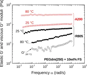
Figure 3.1. Elastic modulus as a function of frequency for dispersions of hydrophobic (R805) and hydrophilic (A200) fumed silica in PEGdm(250) at 25 and 80 °C. ………..……….59
Figure 3.2. Suggested mechanism for PEGdm(250) adsorption on the surface of hydrophilic fumed silica at higher temperature. The arrows identified by (a) and (b) indicate the two suggested hypothesis for increase in the elastic modulus of the A200 gels when thermal energy is provided to the system.59
PEGdm(250) at different concentrations. The dynamic rheological experiments were performed in the rheometer at 1 rad/s. ……….61
Figure 3.5. Effect of thermal treatment on the rheological properties of various dispersions of hydrophilic fumed silica (A200): (a) Elastic modulus (G′) and (b) Normalized elastic modulus (G′/G′t=0) vs time at 80 °C. The thermal treatment was performed in the rheometer at 80 °C and 1 rad/s………...64
Figure 3.6. Elastic modulus versus frequency at 25 and 80 °C for 2 wt% hydrophilic FS (A200) in PEGdm(250) ………65
Figure 3.7. Dependence of the elastic modulus on volume fraction for dispersions of hydrophilic (A200) fumed silica in PEGdm(250) at 25 and 80 °C……….67
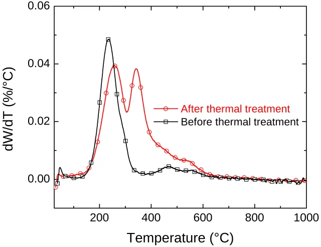
Figure 3.8. TGA of fumed silica extracts before and after thermal treatment at 80 °C for 4 h. In all cases the silica was washed and dried several times until constant weight loss was obtained. The temperature scans were conducted at 10 °C/min. ………..………..66
Figure 3.9. Derivative of the weight loss (dW/dT) as a function of temperature of fumed silica extracts before and after thermal treatment at 80 °C for 4 h. ………..………70
Figure 3.10. Suggested mechanism for the condensation of PEGdm(250) molecules on the surface of hydrophilic fumed silica upon heating to 80 °C………72
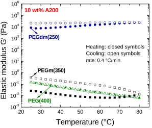
°C/min. The data correspond to two steps, heating (closed symbols) and cooling (open symbols) after the previous step………72
Figure 3.12. Effect of PEG end group amount on the rheological properties of hydrophilic (A200) fumed silica dispersions as a function of temperature.………..73
Figure 4.1. Frequency sweeps of PEGdm(250)+10wt% fumed silica at 25 °C. Results are shown for different blends of hydrophilic (A200) and hydrophobic (R805) fumed silicas. The inset shows the elastic modulus at 1 rad/s as a function of A200 content in the mixture. The dashed line represents the log-additive mixing rule. ………85
Figure 4.2. Dynamic moduli as a function of frequency at various temperatures for (a)25/75 FS A200/R805 and (b)75/25 FS A200/R805………..87
Figure 4.3. Elastic modulus as a function of strain at various temperatures for (a)25/75 FS A200/R805 and (b)75/25 FS A200/R805. Samples contain 10 wt% FS in PEGdm(250). ……….89
Figure 4.4. Effect of temperature on the critical strain and ultimate modulus before catastrophic failure for gels of 10 wt% mixed FS (A200/R805) in PEGdm(250). ………..………92
PEGdm(250)+10wt% FS at different temperatures. The concentration of FS is expressed in g of hydrophilic per g of mixed FS (hydrophilic (A200) + hydrophobic (R805)) in the colloid. ………..93
Figure 4.9. Dynamic moduli as a function of frequency at various temperatures for (a)25/75 FS A200/R805 and (b)75/25 FS A200/R805……….100
Figure 4.10. Effect of fumed silica surface chemistry on the elastic modulus of PEG(200)+10wt% FS at different temperatures. The concentration of FS is expressed in g of hydrophilic per g of mixed FS (hydrophilic (A200) + hydrophobic (R805)) in the colloid………...102
Figure 5.1. Dynamic moduli as a function of frequency for as received and purified PEO 200k at 80 °C. ……….104
Figure 5.2. Thermal properties of the purified and as received PEO 200k. (a) DSC cooling scans and (b) DSC heating scans. In all cases, the scans were performed at 10 °C/min. ………..105
Figure 5.3. Dynamic moduli as a function of frequency for PEO 200k without fumed silica and with 10 wt% of hydrophilic (A200) or hydrophobic (R805) fumed silica. The data were collected at 80 °C. ………..……107
Figure 5.4. Elastic and viscous (a) and elastic (b) moduli as a function of frequency for PEO 200k/PEGdm(250) blends + 10 wt% hydrophilic (A200) FS……120
200k/PEGdm(250) + 10 wt% FS at different frequencies (ω). The closed symbols correspond to the blends containing hydrophilic FS (A200) and the open symbols to the blends containing hydrophobic FS (R805). The connecting lines are added to guide the eye. ………..112
Figure 5.7. Elastic modulus versus stress amplitude for mixed systems containing hydrophilic (A200) and hydrophobic FS. Experiments were done at 80 °C. ………..……….124
Figure 5.8. Effect of mixing method (solution versus melt mixing) on the rheological properties of mixed-MW systems. All the experiments were performed at 80 °C. ………..………125
List of Tables
Table 1.1. Physical properties of some commercially available fumed silicas…..……6
Table 2.1. Physical properties of commercial and in0house modified FS used in this work………..……28
Table 3.1. Molecular characteristics of the polyethers employed in this work…..….53
1
1.1
Motivation and Goals
Fumed silica based gels and nanocomposites have been the subject of several research studies1-4 due to their importance in applications such as reinforced polymeric systems,
membranes, composite polymer electrolytes, and fiber optics cable gels. Fumed silica is an amorphous, non-porous form of silicon dioxide (SiO2) with a very low density and a powdery
appearance. It is prepared by flame hydrolysis of SiCl4 with the end product consisting of
primary spherical particles of ~10 nm in diameter which fused together to form branched structures of 100 nm or more (details of this process are presented in Figure 1.1 and section 1.1.2). The native surface is hydrophilic, with silanol groups (Si-OH) being the characteristic functionality. These silanol groups can be replaced by other moieties, so that interactions between particles or particle-medium can be tuned. When such nano particles are added to a continuum phase to prepare a colloidal dispersion, three states of aggregation are likely to occur5, 6: a) particulates do not interact with each other (or interactions are minimal) and
remain isolated, b) fumed silica particles form clusters or flocs, and c) a three dimensional network is formed by flocculation of the clusters. The first situation is known as a stable suspension and the last one is usually referred to as a gel.
An overarching goal of this project is to combine micro- and macroscopic techniques to evaluate the behavior of fumed silica particles in continuum phases. In particular, low-molecular weight and high-low-molecular weight poly(ethylene oxide) will be used as the continuous media in which fumed silica particles containing different surface chemistries will be dispersed. These systems have been extensively used1, 4, 6-14; however, a fundamental
understanding on the nature of interactions has not been correlated with the observed properties in a systematic fashion that allows for the prediction of a desired particular behavior under both equilibrium and flow circumstances. In particular, several issues remain unresolved. These include:
What are the mechanisms by which fumed silica particles containing different surface chain lengths interact with non-polar solvent media?
How can we tailor the properties of fumed silica gels that are formed by mixing particles with different surface functionalities?
What is an adequate way to prepare fumed silica nanocomposites containing high- and low-molecular weight polyethylene oxides? How does composition influence rheological behavior in a wide range of temperatures, crystallinity?
How is the wall slip phenomenon in fumed silica nanoparticulate gels affected by the surface functionality of both particles and the surface of rheometer plates?
1.2
Background
1.2.1
Fumed silica: synthesis, characteristics and use
The molecular reaction of silicon tetrachloride (SiCl4) vapor in a flame of
oxygen and hydrogen leads to the formation of an amorphous form of silicon dioxide (SiO2)
through the reaction:
4 2 2 2
SiCl + 2H + O → SiO + 4HCl (1)
SiCl4 H2 air
Reaction
Nucleation
Reaction: SiCl4 + H2 + O2 → SiO2 + HCl
collision collision collision
Primary particulate Aggregates BURNER
TUBE
FLAME COOLING
Agglomerates
SiCl4 H2 air
Reaction
Nucleation
Reaction: SiCl4 + H2 + O2 → SiO2 + HCl
collision collision collision
Primary particulate Aggregates BURNER
TUBE
FLAME COOLING
Agglomerates
Figure 1.1. Schematic of fumed or pyrogenic fumed silica formation8, 15.
The conditions under which the process takes place allows for the product to have different physical properties, such as particle size, and surface area, among others. Typically primary particle sizes oscillate between 10 to 20 nm, and the surface areas between 100 to 400 m2 per g, due to the branched structure of the aggregates. These characteristics give
fumed silica interesting and convenient properties as a reinforcing material, as well as thickener agents, due to its ability to create three-dimensional networks16-18. The native form
of fumed silica has a hydrophilic surface chemistry, being that the silanol (Si-OH) and siloxane (Si2O) functional groups play a major role in the behavior of fumed silica. Silanol
density is approximately17 2.5 Si-OH per nm2, which gives the possibility of interactions
through hydrogen bonding not only between particles, but also with solvent media and polymers.
alkyltrialkoxysilanes, X(CH2)n(SiO)3, have been extensively employed to modify the silica
surface. The functional group X of the silane coupling agent may be an amine, alcohol, epoxide, or acrylate group capable of interacting with the matrix19, 20. Chlorosilanes have
been also employed as silica surface modifiers due to their use as deactivating agents. These reactions provide a way to improve the compatibility between matrix (or solvent medium) and filler in composite materials as well as to effectively modify flow properties in low-molecular weight polymers. As will be described later, this particular property is of paramount importance in composite polymer electrolytes used in lithium batteries applications since high ionic conductivity of low-molecular weight polymers can be combined with the high mechanical properties that the fumed silica networks provide to these materials21-25.
Based on the versatility, economics, and availability of fumed silica our group has proposed novel composite materials which serve from the interactions (chemical or physical) between solvent media and filler that can be used in lithium batteries applications1, 2. Table
1.q shows some of the commercially available fumed silica types as well as their respective physical properties.
Table 1.1. Physical properties of some commercially available fumed silicas
Fumed silica name Dominant surface group
OH density (mmol/g)
Silanol (Si-OH) unreacted (%)
A200 Silanol (Si-OH) 0.84 100
R974 Di-methyl (Si-(CH3)2) 0.42 50
1.2.2
Colloidal interactions in self-assembled fumed silica nanocomposites
Suspensions of small particles are often called “colloids”. Similar to molecules composed of covalently bonded atoms, the force between colloidal particles can be described by using a potential function W(r), which in the case of spherical molecules separated by a distance r is given by:
dW
F
dr
= −
(2)where F is the force between molecules.
The basic forces governing colloidal particle suspensions can be divided into several groups: excluded volume, van der Waals, electrostatic, hydrogen bonding, and hydrophobic5, 26. Excluded volume interactions are a repulsive force that result from
crystalline ordering. These types of interactions are short-ranged and they depend on the flexibility of the particles interacting. The second type, van der Waals interactions, arises from attractive dipole-dipole interactions, and can be divided into London or dispersion interactions, Keesom, and Debye forces. In suspensions, van der Waals forces are considered on a continuum basis. The interaction potential between spherical particles A of radius a in a medium B, can be calculated using eqn. 3:
(
)
2(
)
2(
)
21
1
1
2 ln 1
12
1
1
1
1
H vdW
A
W
x
x
x
⎧
⎡
⎤
⎫
⎪
⎢
⎥
⎪
= −
⎨
+
+
−
⎬
⎢
⎥
+
−
+
+
⎪
⎣
⎦
⎪
⎩
⎭
where AH is the Hamaker constant, which can be estimated from the Leifshitz theory of dispersion forces in a continuum as:
(
)
(
)
2
2 2 2
3
2 2 2
3
3
4
16 2
A B e A B
H B
A B
A B
h
n
n
A
k T
n
n
ε − ε
υ
−
⎛
⎞
=
⎜
⎟
+
ε + ε
⎝
⎠
+
(4)
Where AH = Hamaker constant
εi = dielectric constant of material i (particle A or medium B)
n = refractive index
νe = main ultraviolet absorption frequency (usually ~ 3 x 10¹⁵ sec-1)
kB = Boltzmann constant
T = absolute temperature
If r is the distance between the centers of the spheres, and D = r – 2a, then x is defined as D/2a. As can be seen from eqns. 3 and 4, van der Waals interactions in suspensions yield particle coagulation, with the Hamaker constant a parameter that allows to quantify the strength of the attractive forces between particles26, 27.
The third type of interactions, electrostatics, is present in materials that contain ions; these interactions are usually expressed in terms of the Poisson-Boltzmann equation. Counterion concentration and medium dielectric constant determine the thickness of the double layer formed next to the charged surface. This thickness is defined by the Debye length, which is sensitive to the electrolyte concentration26, 27. A theory that describes net
and Overbeek in the 1940’s. The so-called DLVO theory postulates that the force between two surfaces can be approximated by the sum of electrostatic and van der Waals interactions. Several approaches have been employed to describe the stability of fumed silica particles in both polar and non-polar media. In some cases, DLVO theory holds and can be used to predict interaction potential and stability; however, in some other cases, the theory does not reproduce the behavior obtained experimentally. In these cases, other type of interactions, such as hydrogen bonding and hydrophobic interactions, play an important role in the system and predictions from the theory are not accurate28-31. Hydrogen bonding is a
type of solvation force between electronegative atoms (like oxygen and fluorine) and hydrogen. It is considered as an electrostatic interaction where the H atom is not shared but remains closer to and covalently bound to its parent atom26 . It is of considerable importance
in colloidal systems since it often induces molecular association. The binding energies in these colloidal systems are of 10 – 40 kJ/mol; this compared with van der Waals interactions binding energies, which are approximately 1 kJ/mol, makes hydrogen bonds a type of interaction considerable strong, though not as strong as covalent or ionic bonds (~ 500 kJ/mol). Additionally, hydrogen bonds are directional and specific, which allows for them to form three-dimensional structures in solids and short-range structures in liquids.
1.2.3
Rheology as a tool for characterizing self-assembled systems
that information on the microstructure in equilibrium and under flow conditions can be obtained by using appropriate rheological techniques. Moreover, valuable knowledge on processing and handling of materials can be also obtained from these measurements. Rheological measurements can be performed under steady or dynamic shear mode and depending upon the response of the fluid, the microstructure can be probed.
1.2.4
Steady shear rheology
In steady shear rheology, a sample is deformed by applying a constant shear rate (γ). After an adequate period of time, the shear stress (τ) reaches steady state and a material function, called the apparent viscosity (η), can be determined by taking the ratio between stress and shear rate:
.
τ
η =
γ
(5)
1.2.5
Dynamic Shear
Oscillatory shear or dynamic mechanical spectroscopy experiments impose small-amplitude oscillatory shearing to the sample. For example, if a sinusoidal strain (γ) is applied:
sin(
)
o
t
γ = γ
ω
(6)where γo is the strain amplitude and ω the frequency of oscillation. The resulting
stress τ varies sinusoidally with time and is given by
sin(
)
o
t
τ = τ
ω + δ
(7)τ is not necessarily in phase with the applied strain (δ is the phase angle), and if γo is
small enough (usually << 1), the stress is represented according to eqn. 8. The regime in which this equation is valid is known to as the linear viscoelastic regime,
( )
t
oG
′
( ) sin(
t
)
G
′′
( )
cos(
t
)
τ
= γ
⎡
⎣
ω
ω +
ω
ω
⎤
⎦
(8)G′(ω) and G′′(ω) are the storage and loss modulus, respectively. The storage modulus is in phase with the strain and is commonly associated with the elastic energy of the material, whereas the loss modulus is in phase with the strain rate and represents the viscous dissipation of that energy5. The ratio G′′/G′ is known as the loss tangent (tan δ) and
is higher than unity for liquid-like materials, and smaller than unity for materials that behave solid-like.
steady shear flow experiments. This is very useful in colloidal systems because the state of aggregation can be associated with the particular rheological response within the linear viscoelastic regime obtained from the dynamic mechanical spectrum of the material, G′(ω)
and G′′(ω).
1.2.6
Rheology and microstructure
In this section, the correlation between rheology and microstructure is addressed. In spite of the fact that rheology as a macroscopic characterization technique cannot specifically elucidate what the nature of the microstructure is, it provides an easily accessible way to correlate this microstructure with the particular responses shown by a system. At this point, it is pertinent to introduce several terms that are commonly used to describe states of aggregation in colloidal systems.
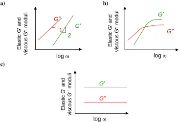
Particles dispersed in a solvent medium possess a non-flocculated or deflocculated microstructure when the forces between particles are negligible. The typical rheological behavior for this type of system is schematized in Figure 1.2(a) where the elastic and viscous moduli are plotted as a function of frequency. It can be seen that for all range of experimentally evaluated frequencies (typically between 0.01 and 100 rad/s) the viscous modulus dominates the rheological response. Similar behavior has been observed for polymer solutions, with a characteristic terminal zone at low frequencies where G′ and G′′ scale with
Figure 1.2(b) shows the rheological response of a flocculated dispersion. The elastic modulus and viscosity increase considerably due to particles aggregation or floc formation. A floc is equivalent to an aggregate; it can be disrupted by shear and its strength depends on the magnitude of the attractive force between particles. This aggregation of particles gives a more elastic material with less marked frequency dependence of G′. The limiting case for particles aggregation corresponds to a gel. Figure 1.2(c) shows that when the forces between particles and the concentration allow for the floc size to increase and form a three-dimensional network; G′ is completely frequency independent and dominates over G′′. This type of microstructure is known as a gel and it exhibits solid-like behavior, similar to chemically cross-linked polymeric networks.
a) b)
c) log ω G¢ G≤ 2 1 Ela s ti c G ′ an d v isc ou s G ′′ m o duli log ω G¢ G≤ log ω G¢ G≤ Elas tic G ′ an d vi sc ou s G ′′ m odu li Elas tic G ′ an d v isc ou s G ′′ m o d u li
1.2.7
Rheology and microstructure of self-assembled fumed systems
The literature on fumed silica as thickening agent and reinforcing material in polymeric systems is considerably extensive16, 18, 31. In this section, a review of the most
important findings of fumed silica fillers in high-molecular weight polymers as well as in organic liquids is presented. In particular, the relationships between microstructure and rheological properties are highlighted.
The use of fumed silica systems prevails due to the possibility of network (gel-like structure) formation in a variety of solvent media. As was mentioned before, this ability has been extended by the modification of its native surface chemistry through chemical reactions. Early studies focused on low-molecular weight poly(dimethyl siloxane) (PDMS) containing fumed silica33, 34. It was found that the filler imparted thixotropic behavior to the
system. The results were interpreted in terms of phenomenological microstructural models of particle interactions through polymer absorption on the silica surface. Khan and Zoeller3
Raghavan et al.4 proposed a useful correlation between the elastic modulus of the
fumed silica network and surface chains and solvent medium solubility parameter difference. The study comprised a variety of polyether liquids and fumed silica particles with octyl chains tethered to the surface. The results suggested that “reverse steric stabilization” dictated flocculation in the systems, higher elastic modulus was observed in those gels with the larger mismatch in solubility parameters.
Scaling relationships showing the dependence of elastic modulus on fractal dimension of the network and volume fraction have been proposed35-37. A power law model described
by:
n
G′ φ∼ (9)
has been suggested, where φ is the particle volume fraction and n a parameter used to characterize the mechanism of aggregation.
If the rate at which two particles stick together is lower than the rate of mass transfer, the mechanism is referred to as chemically limited aggregation, and n takes a value of 4.5 ± 0.2. For diffusion limited cluster-cluster aggregation, n has a value of 4.0 ± 0.538.
Khan and Zoeller3 reported a value of n = 4 in fumed silica dispersed in mineral oil; this is
in excellent agreement with the predicted value of Buscall et al35. Walls39 obtained n value
of 4.1 ± 0.4 for colloidal gels of hydrophobic fumed silica (~ 50% surface coverage of C8H17)
in poly(ethylene glycol) dimethyl ether (250 Mn), suggesting a diffusion limited
concentrations ranging up to 1.86M, suggesting that the salt does not affect the mechanism of gel formation.
The behavior of fumed silica particles in high-molecular weight polymer matrices is significantly different that that observed in low-molecular weight systems. The high viscosity limits the possibility of interaction between colloidal particles. As such, the volumes required to impact the mechanical properties and flow behavior are higher than those required for molar mass solvents. A limited number of studies have been undertaken on fumed silica/high-molecular weight polymer systems. Zhang and Archer40 studied high
molecular weight poly(ethylene oxide) (PEO) containing silica nanoparticles. They found that filler particles have a stronger effect on the low-frequency rheological response than at high-frequency values, suggesting that the relaxation dynamics is more affected than the plateau modulus by the presence of silica particles. Thermal annealing of samples after compounding as well as compounding method seem to have an important effect on the microstructure. After annealing two possible situations are suggested, the occurrence of flocculation and the increase of the immobilized PEO layer on the silica particles. Tsagaropoulus and Eisenberg41 reported a second glass transition temperature (T
g) in a system containing silica particles in high-molecular weight polymers. This transition, which occurred at higher temperature than the bulk polymer, was interpreted in terms of the presence of a low mobility group of chains.
The microstructure and in consequence, the mechanical properties of filled polymers are strongly affected by the nature of the reinforcing particles. Aranguren42 reported that
formed network structures at higher volume fractions. For polymers capable of interacting with the particles surface through specific interactions such as hydrogen bonding, an increase in viscosity has been reported43. Similar results were reported by Yerian et al.44 in PEO
containing hydrophobic and hydrophilic fumed silica particles. Hydrophilic fumed silica systems are more elastic due to the strongest bridging effect between particles and polymer.
1.3
References
1. Raghavan, S. R.; Riley, M. W.; Fedkiw, P. S.; Khan, S. A., Composite polymer electrolytes based on poly(ethylene glycol) and hydrophobic fumed silica: Dynamic rheology and microstructure. Chemistry of Materials 1998, 10, (1), 244-251.
2. Hou, J.; Baker, G. L., Preparation and characterization of cross-linked composite polymer electrolytes. Chemistry of Materials 1998, 10, (11), 3311-3318.
3. Khan, S. A.; Zoeller, N. J., Dynamic Rheological Behavior of Flocculated Fumed Silica Suspensions. Journal of Rheology 1993, 37, (6), 1225-1235.
4. Raghavan, S. R.; Hou, J.; Baker, G. L.; Khan, S. A., Colloidal interactions between particles with tethered nonpolar chains dispersed in polar media: Direct correlation between dynamic rheology and interaction parameters. Langmuir 2000, 16, (3), 1066-1077.
5. Larson, R. G., The Structure and Rheology of complex Fluids. Oxford University Press, Inc.: New York, 1999.
6. Raghavan, S. R.; Khan, S. A., Shear-Induced Microstructural Changes in Flocculated Suspensions of Fumed Silica. Journal of Rheology 1995, 39, (6), 1311-1325.
8. Barthel, H.; Rosch, L.; Weis, J., Fumed Silica- Production, Properties, and Applications. In Organosilicon Chemistry II: From Molecules to Materials, Auner, N.; Weis, J., Eds. VCH Publishers: Weinheim, Germany, 1996; pp 761-777.
9. Khan, S. A.; Baker, G. L.; Colson, S., Composite Polymer Electrolytes Using Fumed Silica Fillers - Rheology and Ionic-Conductivity. Chemistry of Materials 1994, 6, (12), 2359-2363.
10. Khan, S. A.; Maruca, M. A.; Plitz, I. M., Rheology of Fumed Silica Dispersions For Fiberoptic Cables. Polymer Engineering and Science 1991, 31, (24), 1701-1707.
11. Raghavan, S. R.; Baker, G. L.; Khan, S. A., Colloidal silica gels for use as novel electrolytes for rechargeable batteries: Synthesis, microstructure and rheology. Abstracts of Papers of the American Chemical Society 1998, 216, U601-U601.
12. Raghavan, S. R.; Fussell, G. W.; Khan, S. A., Fumed silica dispersions in polymeric liquids: Evidence for site-specific colloidal interactions. Abstracts of Papers of the American Chemical Society 1997, 214, 332-POLY.
13. Raghavan, S. R.; Khan, S. A., Shear-thickening response of fumed silica suspensions under steady and oscillatory shear. Journal of Colloid and Interface Science 1997, 185, (1), 57-67.
14. Raghavan, S. R.; Walls, H. J.; Khan, S. A., Rheology of silica dispersions in organic liquids: New evidence for solvation forces dictated by hydrogen bonding. Langmuir 2000, 16, (21), 7920-7930.
15. Legrand, A. P., The Surface Properties of Silicas. John Wiley & Sons: London, 1998. 16. Iler, R. K., The Chemistry of Silica: Solubility, Polymerization, Colloid snf Surface
Properties, and Biochemistry. John Wiley & Sons: New York, NY, 1979; p xxiv, 866. 17. Basic Characteristics of Aerosil; Degussa Technical Bulletin No. 11; Degussa Corp.:
Akron, OH, 1993.
18. Mathias, J.; Wannemacher, G., Basic Characteristics and Applications of Aerosil. Journal of Colloid and Interface Science 1988, 125, 61-68.
20. Joseph, R.; Zhang, S. M.; Ford, W. T., Structure and dynamics of a colloidal silica poly(methyl methacrylate) composite by C-13 and Si-29 MAS NMR spectroscopy. Macromolecules 1996, 29, (4), 1305-1312.
21. Scrosati, B.; Croce, F.; Panero, S., Progress in lithium polymer battery R&D. Journal of Power Sources 2001, 100, (1-2), 93-100.
22. Liu, Y.; Lee, J. Y.; Hong, L., Functionalized SiO2 in poly(ethylene oxide)-based polymer electrolytes. Journal of Power Sources 2002, 109, (2), 507-514.
23. Walls, H. J.; Riley, M. W.; Fedkiw, P. S.; Spontak, R. J.; Baker, G. L.; Khan, S. A., Composite electrolytes from self-assembled colloidal networks. Electrochimica Acta 2003, 48, (14-16), 2071-2077.
24. Walls, H. J.; Zawodzinski, T. A. J., Anion and Cation Transference Number by Electrophoretic NMR of Polymer Electrolytes Sum to Unity. Journal of Electrochemical Society Letters 2000, 3, (7), 321-324.
25. Walls, H. J.; Zhou, J.; Yerian, J. A.; Fedkiw, P. S.; Khan, S. A.; Stowe, M. K.; Baker, G. L., Fumed silica-based composite polymer electrolytes: synthesis, rheology, and electrochemistry. Journal of Power Sources 2000, 89, (2), 156-162.
26. Israelachvili, J. N., Intermolecular and Surface Forces. 2nd ed.; Academic Press London: London, 1991; p xxi, 450.
27. Evans, D. F.; Wennerström, H., The colloidal domain: where physics, chemistry, biology, and technology meet. 2nd ed.; Wiley-VCH: New York, 1999; p xl, 632.
28. Russel, W. B., Review of the Role of Colloidal Forces in the Rheology of Suspensions. Journal of Rheology 1980, 24, (3), 287-317.
29. Metzner, A. B., Rheology of Suspensions in Polymeric Liquids. Journal of Rheology 1985, 29, (6), 739-775.
30. Vincent, B.; Kiraly, Z.; Emmett, S.; Beaver, A., The Stability of Silica Dispersions in Ethanol Cyclohexane Mixtures. Colloids and Surfaces 1990, 49, (1-2), 121-132.
31. Chen, M.; Russel, W. B., Characteristics of Flocculated Silica Dispersions. Journal of Colloid and Interface Science 1991, 141, (2), 564-577.
33. Kosinski, L. E.; Caruthers, J. M., Rheological Properties of Poly(Dimethylsiloxane) Filled with Fumed Silica.2. Stress-Relaxation and Stress Growth. Journal of Non-Newtonian Fluid Mechanics 1985, 17, (1), 69-89.
34. Kosinski, L. E.; Caruthers, J. M., The effect of molecular weight on the rheological properties of poly(dimethylsiloxane) filled with fumed silica. Rheologica Acta 1986, 25, 153-160.
35. Buscall, R.; Mills, P. D. A.; Goodwin, J. W.; Lawson, D. W., Scaling Behavior of the Rheology of Aggregate Networks Formed from Colloidal Particles. Journal of the Chemical Society-Faraday Transactions I 1988, 84, 4249-4260.
36. Rueb, C. J.; Zukoski, C. F., Viscoelastic properties of colloidal gels. Journal of Rheology 1997, 41, (2), 197-218.
37. Shih, W. H.; Shih, W. Y.; Kim, S. I.; Liu, J.; Aksay, I. A., Scaling Behavior of the Elastic Properties of Colloidal Gels. Physical Review A 1990, 42, (8), 4772-4779. 38. Buscall, R.; Mills, P. D. A.; Yates, G. E., Viscoelastic Properties of Strongly
Flocculated Polystyrene Latex Dispersions. Colloids and Surfaces 1986, 18, (2-4), 341-358.
39. Walls, H. J. Colloidal Silica Gels as Composite Electrolytes: Rheology and Ion Transport. Ph.D. Thesis, North Carolina State University, Raleigh, NC, 2002.
40. Zhang, Q.; Archer, L. A., Poly(ethylene oxide)/silica nanocomposites: Structure and rheology. Langmuir 2002, 18, (26), 10435-10442.
41. Tsagaropoulos, G.; Eisenberg, A., Dynamic-Mechanical Study of the Factors Affecting the 2 Glass- Transition Behavior of Filled Polymers - Similarities and Differences with Random Ionomers. Macromolecules 1995, 28, (18), 6067-6077.
42. Aranguren, M. I.; Mora, E.; Degroot, J. V.; Macosko, C. W., Effect of Reinforcing Fillers On the Rheology of Polymer Melts. Journal of Rheology 1992, 36, (6), 1165-1182.
2
Yield Stress vs. Wall Slip in Colloidal Gels
of Fumed Silica: Effects of Geometry
Surface Energy on Slip Properties
Abstract
A combination of dynamic oscillatory experiments and flow visualization with a CCD camera is employed to evaluate the yield stress of colloidal silica (fumed) gels in low-molecular weight polyether poly(ethylene glycol)dimethyl ether (PEGdm(250)). In particular, the combination of dynamic rheology with the paint mark technique, enables us differentiate between slip and yielding. We explore how the chemical composition of the shearing surface modifies the flow behavior of gels containing particles with different surface functionalities. To do this, a set of hydrophobic FS particles was dispersed in PEGdm(250) and the effect of the testing geometry surface energy on the slip properties of the gels used as a tool to evaluate the role that colloidal interactions play during flow. Dynamic time and stress sweep experiments flow visualization suggest that specific interactions between the nanoparticles in the gel and the plates’ surface control the extent of slip. We found that in the case of hydrophobic FS gels sheared on hydrophobic surfaces, the wall slip occurs but it is delayed with respect to the hydrophilic or smooth (stainless steel) geometry. These results shed new light into the processing and microstructural dynamics of complex nanoparticulate gels.
2.1
Introduction
Complex fluids have gained special interest over the past years not only because of the appearance of new synthetic materials, but also due to the development of multicomponent systems which combine specific properties of the individual components. In addition, the possibility to utilize and promote interactions among the components is of particular interest, as those interactions allow for the development of responsive systems, materials that can be specifically tuned so that they perform differently based on the interactions dominating the microstructure, among others. The mechanisms of assembly and the role that those interactions play under particular events add on to this interest as they dictate the fluid behavior under many circumstances 1
Whether during processing these complex fluids into end products or during their performance in a particular application, such materials are submitted to flow and deformation; therefore, a deep understanding of the fluid response under stress or deformation is of paramount importance from both manufacturing and research standpoints. Our group has been involved in the research of some of these complex fluids systems and their flow properties for the past few years. Moreover, the dynamic and steady flow properties of fumed silica suspensions have been extensively investigated as these can be employed in various fields such as composite polymer electrolytes 2-4, paints, fiber optics
cable gels, and reinforced polymeric systems among others 5-8.
Fumed silica is an amorphous, non-porous form of silicon dioxide (SiO2) with a very
low density and a powdery appearance. It is prepared by flame hydrolysis of SiCl4 with the
together to form branched structures of 100 nm or more9, 10. The native surface is
hydrophilic, with silanol groups (Si-OH) being the characteristic functionality. These silanol groups can be replaced by other moieties, so that interactions between particles or particle-medium can be tuned.
Under certain circumstances, usually dictated by the solvent media and surface chemistry of the fumed silica particles, these suspensions flocculate and form gels, i.e., solid-like materials 5, 6, 11-13, which can flow at a specific shear rate/stress. In these situations,
characterizing the stress or shear rate at which the material starts to flow, namely finding the yield stress, is of primary significance as this is a signature property which determines the processing and application windows. Numerous studies have emphasized the necessity to establish a method or protocol to accurately characterize the yield stress of a complex fluid as experimental artifacts, inherent to either the sample or the type of geometry, can lead to erroneous values of such property.
One of the most common sources of error during yield stress determination of solid-like suspensions is the occurrence of wall slip 14-17 or wall depletion effects as referred to by
Barnes 14. The migration of particles away from the geometry solid surfaces has been
attributed to the hydrodynamic and entropic forces that result when the bulk is submitted to flow 14. Reliable measurements have been obtained by modifying the walls surface,
especially roughening by sandblasting or machining specific shapes onto the plates or cylinders 18. Walls et al16 suggested chemically altering the surface of the rheometer plates
silica particles whereas hydrophilic test geometry surfaces resembled the behavior obtained with smooth geometries. Princen 19 reported that by treating the surface of the concentric
cylinders geometry, reproducible flow data for concentrated oil-in-water emulsions was obtained. Moreover, the aqueous phase of the emulsion wetted the surface and this is kept separate from the adjacent layer of oil droplets by a thin aqueous film. This allowed them to study not only the rheological properties of the emulsion but also those of the wall film. Léger et al. 20 used near-field laser velocimetry to measure the local velocity of a polymer
melt at the solid-polymer interface. By “decorating” the surface, i.e., by controlling the chemistry of the surface through grafting, the authors found that the slip velocity was strongly dependent on the molecular weights of the bulk and surface chains, and surface density. In addition, more recent studies of hexadecane on modified sapphire surfaces made by Pit et al.21 show that the strength of the fluid-surface interactions and the roughness at
molecular scale control slip at the wall. The no slip boundary condition is maintained for incomplete fluorinated monolayer surface while the lyophobic surfaces promoted slip, indicating that both adhesion and roughness at molecular level control the extension of slippage.
between wall slip and yield stress is, even with the existent technologies for slip prevention, an unresolved issue. This follow-up paper uses an approach that not only allows to accurately determine the yield stress in colloidal gels, but also establishes a way of interpreting wall slip in terms of specific interactions between the surface (of the test geometry) and the nature of the tested material.
In order to study the effects of test geometry surface energy on the occurrence and development of wall depletion, a series of fumed silica gels were sheared on surfaces with very different surface energies, i.e. high surface energy or hydrophobic and low surface energy or hydrophilic. The occurrence of wall slip as well as the time dependence of wall slip at various stress values were evaluated for each surface and compared to the results obtained with serrated plates by using the paint mark method suggested by Aral and Kalyon 22. A different approach from the traditional steady flow measurements was
employed to examine wall slip. Our approach entailed the use of dynamic measurements, in particular, dynamic oscillatory stress and/or time sweeps, simultaneously with the images collected from a CCD camera during the course of the experiments.
2.2
Experimental
2.2.1
Materials and Methods
FS surface modification. A200 has a surface area of 200 m2/g, a particle size of 12 nm 23,
and a surface silanol (Si-OH) content of 2.5 Si-OH groups/nm2 24. Hydrophobic fumed silicas
were synthesized in our laboratory by substituting surface Si-OH moieties through chlorosilylation reactions. Three different alkyl chains were attached on the surface of A200: decyl (A200-C10), dodecyl (A200-C12), and octadecyl (A200-C18) alkyl chains. Commercial octyl-modified fumed silica, Aerosil R805, was also obtained from Degussa. The details of the surface modification are described elsewhere 25 and the physical characteristics of both
commercial and in-house modified fumed silicas are listed in Table 2.1. The dispersions were prepared by high-shear mixing 10 wt% of previously vacuum-dried fumed silica (3 days, 120 °C) in the solvent; the resulting product was kept in vacuum for 2 h in order to extract air bubbles, and the samples were used within 24 h of their preparation.
Dynamic rheology experiments were performed in a stress-controlled rheometer TA Instruments AR2000 at 25 °C. In order to examine the effect of rheometer plate surface hydrophobicity on gel rheology a procedure based on that described by Walls and co-workers 16 was used to coat the plates with poly(dimethyl siloxane) PDMS which was later
on modified to obtain different surface energy. However, in this work, poly(dimethyl siloxane) PDMS model networks were used instead of commercial Sylgard-184 as a way to control composition and degree of crosslinking. The PDMS networks were prepared, as suggested by Patel et al. 26 by vigorously mixing the needed amounts of crosslinker
crosslink at room temperature for 1 week. The parallel plate test geometry was coated with the PDMS model network films and tested under adequate dynamic oscillatory shear conditions in order to verify that the shear stress required to detach the PDMS film from the plates surface exceeded the maximum shear stress employed during all stress sweeps applied to our samples by at least 50X. PDMS model network films have a water contact angle of 109°, which indicates that the surface is hydrophobic. In order to decrease the surface energy and obtain our second test geometry surface type, i.e. to render the surface hydrophilic, PDMS networks were treated in a UVO chamber (Jetlight Company, Inc. model 42) for 30 min 27. The resulting water contact angle was less than 15°, indicating that
the surface had successfully changed its surface energy. In order to avoid surface reconstruction and therefore changes in the contact angle 27, hydrophilic PDMS films were
used within 5 h of applying the UV treatment. Furthermore, the contact angle was measured after conducting the experiments and compared to the original values. In all cases, the measured contact angle values were the same within experimental error.
going from 0.4 – 40 rad/s at a stress within the sample linear viscoelastic regime and followed by a 15 min delay, a protocol we have ahead established for this system16.
Table 2.1. Physical characteristics of the commercial and in-house modified fumed silica used in this work
Fumed silica
Surface group
Fraction of unreacted
Si-OH (%)
(a)A200 Si-OH 100.0± 0.2
A200-C8 -C8H17 52.0 ± 0.1
A200-C10 -C10H21 50.5 ± 0.1
A200-C12 -C12H25 61.1 ± 0.1
A200-C18 -C18H37 61.1 ± 0.2
(a) determined by thermogravimetric analysis TGA
2.2.2
Flow visualization
Direct visualization of the slip phenomenon was facilitated by using a CCD camera (see Figure 2.1). A straight line was painted from the top to the bottom plate, and the onset of slip was registered as the stress (or time) at which the paint mark lost connectivity with the moving plate (top) 22. It is important to mention that the slip phenomenon
observations were done during dynamic oscillatory sweeps (time or stress); therefore, we combined direct visualization with evaluation of the strain waveform in order to determine wall slip and distinguish it from yield stress 28. This approach allowed us to obtain clear
CCD camera
Sample
Optic fiber lamp
Computer image
Paint mark
Lens
Figure 2.1. Flow visualization setup showing a schematic of the paint line technique for determining slip velocity.
2.3
Results and Discussion
2.3.1
Linear viscoelastic properties of fumed silica gels
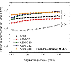
10-1 100 101 102 102
103 104
G′
Ela
s
tic
G
′
and vi
scous
G
′′
M
odul
i (
P
a)
Angular frequency ω (rad/s) A200
A200-C8 A200-C10 A200-C12
A200-C18 FS in PEGdm(250) at 25°C G′′
Figure 2.2. Elastic and viscous moduli as a function of frequency for the five dispersions of fumed silica (10wt%) in PEGdm(250).
energy in the system. As a result, a network of A200 particles physically linked through the surface silanol groups is formed and the system behaves like a gel.
For the hydrophobic FS particles, as the chain length of tethered molecules increases from C-8 to C-18, both van der Waals interactions and reverse steric stabilization dominate the gel formation mechanism 5. It is noticeable that G′ of A200-C10 and A200-C12 FS gels
are very close to each other; however, for the longest alkyl chain-modified FS employed in this work, A200C-18, there seems to be an additional contribution to the gel modulus provided by the attached chains. If the chains are in the crystalline state, as it has been suggested by Snyder and Allara 29 for a monolayer on a silicon wafer, the rigidity of the
system will increase by the presence of an additional layer of a crystalline corona on the FS particles. Allara et al. 30 showed that for disordered monolayers of alkyl chains a distinct
change in surface wetting behavior occurred for chains between 14 and 17 carbon atoms. This was attributed to ordering (crystallization) of the chains and increase of chain extension. If this is the case, as it was mentioned before, for A200-C18 particles, the effective radius will increase by about 2.2 nm; this will in turn increase the effective volume fraction as well as the rigidity of the particles.
not solvate the surface of the particles. Interactions between the hydrophobic chains govern the gel formation mechanism. Finally, case C corresponds to highly hydrophobic particles where the longer alkyl chains not only shield the Si-OH groups completely, but also increase the effective particle size, especially if the chains are capable of crystallizing.
The results shown in this section suggest that the elastic modulus of hydrophobic FS particles increases with increasing the alkyl chain length of the modified FS; this behavior is more noticeable at lower frequencies and attributed to an additional increase in the rigidity of the particles given by the fact that the longer chains are capable of crystallizing. In addition, reverse steric stabilization seems to be the governing mechanism in the gel formation process for gels of longer alkyl-covered fumed silica nanoparticles in PEGdm(250).
H O Si O
H
Si
Case A
Case B
V
stericV
van der WaalsCase C
V
stericV
van der WaalsC-0 C-8 C-18
H O Si O
H
Si H
O Si O
H
Si
Case A
Case B
V
stericV
van der WaalsCase C
V
stericV
van der WaalsC-0 C-8 C-18
2.3.2
Yield stress
vs.
wall slip: effects of surface chemistry on slip of FS
particulate gels
Walls et al 16 suggested that specific interactions between the fumed silica particles
10-1 100 101 102 103 100 101 102 103 104
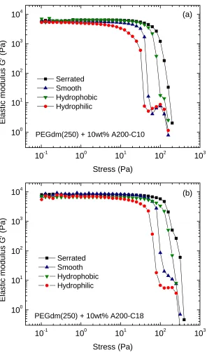
PEGdm(250) + 10wt% A200-C10
El as ti c m o du lu s G ′ (Pa) Stress (Pa) Serrated Smooth Hydrophobic Hydrophilic (a)
10-1 100 101 102 103
100 101 102 103
104 (b)
PEGdm(250) + 10wt% A200-C18
El as ti c m o du lu s G ′ (Pa) Stress (Pa) Serrated Smooth Hydrophobic Hydrophilic
Figure 2.4. Elastic modulus as a function of stress amplitude for (a) A200-C10 and (b) A200-C18 fumed silica in PEGdm(250) at 25 °C.
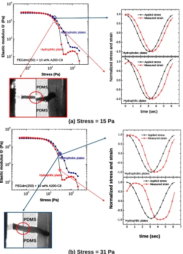
due to deformation and breakdown of the microstructure (i.e., yielding). Though G′ is the same for all geometries in the linear region, the rheological response obtained with the four surfaces after the critical stress is overcome differs considerably. When roughened surface plates are employed, a continuous decrease of G′ with stress amplitude is observed; however, with smooth, hydrophobic and hydrophilic surfaces, G′ drops in a “two-step” fashion. This behavior has been previously observed and it is ascribed to as wall slip 14, 31. In colloidal
systems, wall slip has been explained in terms of the presence of a particle-lean layer with different flow behavior than the bulk; the material next to the wall deforms more than the bulk leading to misinterpretation of the observed flow behavior.
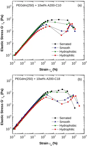
To further examine the effects of the length of alkyl chains tethered to the FS particles on yield behavior and how this is influenced by the test geometry surface chemistry, we show in Figure 2.5 the in-phase component of the stress as a function of the strain amplitude for gels of hydrophobic FS particles (A200-C8, A200-C10, A200-C12, and A200-C18). By determining the point at which the elastic stress reaches its maximum value, we determined the yield stress of the materials (see Figure 2.5). This approach is referred to as the elastic stress method for determination of the yield stress32, 33 and it has been
suggested as an alternative to steady shear flow methods for determining yield stress since it is less subjective, it is based on simple and reliable experiments (dynamic oscillatory), and closely matches the results obtained with steady stress methods 16, 33. In all cases, the values
lowest for the hydrophilic geometry; however, the hydrophobic test geometry gives yield stress values that are closer to the ones obtained with the “control” geometry.
10-3 10-2 10-1 100 101 102 103 104
10-1 100 101 102
103 PEGdm(250) + 10wt% A200-C10 (a)
El as tic Stre ss G ′ γ o (P a)
Strain γ
o (%)
Serrated Smooth Hydrophobic Hydrophilic
10-3 10-2 10-1 100 101 102 103 104
10-1 100 101 102 103 E las tic S tres s G ′ γ o (Pa)
Strain γo (%)
Serrated Smooth Hydrophobic Hydrophilic PEGdm(250) + 10wt% A200-C18 (b)
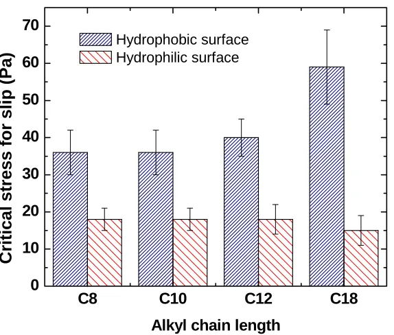
Figure 2.6 summarizes the yield stress values obtained for all the FS gels when tested using hydrophobic and hydrophilic plates. We observe that as the sample starts to get closer to the “slipping regime” or closer to the “yielding point” (we discuss slip vs. yield in subsequent section), whichever occurs first, the hydrophobic particles remain “affixed” to the hydrophobic surface up to stress values that are higher than those observed with the hydrophilic plates. We interpret these observations in terms of the attraction developed between the alkyl chains covering the surface of the FS particles and the hydrophobic test geometry. Conversely, when the interactions are not favored such as in the case of hydrophilic plates and hydrophobic FS particles, where the interaction potential is expected to be repulsive, the particles do not stick to the surface and the estimated yield stress value is even lower than that obtained with the regular geometry surfaces, which are slightly hydrophobic (water contact angle θ of 56°).
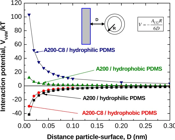
Figure 2.7 shows an example of the calculated van der Waals interaction potential for gels of octyl-modified FS particles in PEGdm(250) as a function of the separation distance between the particles and the surface. It can be seen that the van der Waals interaction potential (VvdW) of hydrophobic PDMS surface and hydrophobic FS particles
(A200-C8, A200-C10, A200-C12, and A200-C18) is attractive (negative VvdW), while that of
the hydrophilic PDMS and hydrophobic FS particles is repulsive (positive VvdW). Likewise,
hydrophilic PDMS and FS A200 show attractive Vvdw, while the opposite is observed for
C8 C10 C12 C18 0
10 20 30 40 50 60 70
Critical stress for slip (
P
a)
Alkyl chain length
Hydrophobic surface Hydrophilic surface
Figure 2.6. Effect of the test geometry surface energy on the critical stress for slip for gels of 10 wt% hydrophobic FS in PEGdm(250) as a function of the length of the alkyl chain attached to the surface of the FS particles.
situation is observed. If we can find an easy method capable of predicting the occurrence of wall slip in a systematic and reliable way, we will have a tool to study the strength of interactions and predict the specific behavior of the material during processing or when a stress or strain field is applied. The next section describes our approach to finding this method and the results we gathered from it.
0.00 0.05 0.10 0.15 0.20 0.25 0.30
-40 -20 0 20 40 60 80 100 120
A200-C8 / hydrophobic PDMS
A200 / hydrophilic PDMS
A200 / hydrophobic PDMS
D R 132 6 A R V D = − Int e ra c tion pot e ntia l, V VdW /kT
Distance particle-surface, D (nm)
A200-C8 / hydrophilic PDMS
Figure 2.7. van der Waals interaction potential (Vvdw) normalized by kT (k is the
Boltzmann constant and T the absolute temperature in K) between FS particles and PDMS covered plates. FS particles are considered to be spherical in shape for the calculations.
2.3.3
Combined flow visualization and mechanical rheology to decipher yield
stress and wall slip
Aral and Kalyon 22 first suggested the use of a very simple yet useful method to