KELLER, TYLER DERRICK. Systematic Approach for Selecting a Microcontroller Development Board to be used in a Control System. (Under the direction of Dr. Jay F. Tu).
Microcontroller development boards have a wide range in capabilities and features resulting in difficulties when attempting to make a selection for use in a system. This research led to the development of a selection guide to assist in choosing a microcontroller development board to be used in a control system. Steps were put forward to detail how to classify and prioritize requirements to ensure the most relevant needs of the system are met. Based on these requirements, a functional design can be generated which can demonstrate how components of the system interact with one another and can lead to a system design.
As the design has been established, the process on selecting the microcontroller development board can now be followed. Generating a hardware block diagram leads to an exact requirement of I/O pins and communication interfaces. This step tends to narrow the focus of the development board search, especially for systems with a high number of required pins. Power considerations are briefly mentioned followed by details about the microprocessor core and memory of the system. These sections do not provide definite recommendations but describe the importance of each feature while also discussing how they relate to system needs.
A case study was conducted to examine the worthiness of the board selection guidelines. An existing system was to be replaced to allow for more exact control over pulses sent to a laser. The guidelines were followed and resulted in the selection of an Arduino Due. Tests were
conducted using the Arduino Due to examine pulse control capabilities. After minor
System
by
Tyler Derrick Keller
A thesis submitted to the Graduate Faculty of North Carolina State University
in partial fulfillment of the requirements for the degree of
Master of Science
Aerospace Engineering
Raleigh, North Carolina 2018
APPROVED BY:
_______________________________ _______________________________ Dr. Scott Ferguson Dr. Larry Silverberg
_______________________________ Dr. Jay F. Tu
ii DEDICATION
iii BIOGRAPHY
iv ACKNOWLEDGMENTS
I would first like to thank my advisor, Dr. Jay Tu, for the opportunity to work with him. His guidance, advice, and motivation throughout this entire process was invaluable and helped me develop as a student and person. I would also like to thank Dr. Scott Ferguson and Dr. Larry Silverberg for serving on my committee. Their feedback and support were greatly appreciated. Next, I would like to thank my friends for creating a great learning environment that was enhanced by their selflessness in helping others achieve their goals. My friendships gained while at NC State will always be remembered and cherished.
v TABLE OF CONTENTS
LIST OF TABLES... vi
LIST OF FIGURES ...vii
Chapter 1: Introduction and Background ... 1
1.1 Motivation ... 1
1.2 Research Goals ... 1
1.3 Examples of Commercial Microcontroller Control Systems ... 2
1.4 Examples of Hobby Microcontroller Control Systems ... 3
Chapter 2: Historical Review ... 4
2.1 Differences between Microcontrollers and Microprocessors ... 4
2.2 Origins of the Microprocessor ... 6
2.2.1 Advancements ... 6
2.3 Development of the Microcontroller ... 7
2.3.1 Advancements ... 8
2.4 Development Platforms ... 8
2.4.1 Development Platform History ... 9
2.4.2 State of the Art ... 9
2.5 Difficulties in Choosing the Appropriate Platform ... 10
Chapter 3: Research Objectives ... 11
Chapter 4: Systematic Design Process ... 13
4.1 Classifying and Prioritizing Needs ... 13
4.2 System Requirements ... 16
4.2.1 Input/Output (I/O) Capabilities ... 19
4.2.2 Power Considerations ... 20
4.2.3 Microprocessor Core ... 21
4.2.4 Memory ... 23
Chapter 5: Case Study ... 27
5.1 Current System Design ... 27
5.2 Requirements for the New System ... 29
5.3 Microcontroller Development Board Selection ... 30
Chapter 6: Results and Discussion ... 38
6.1 Fulfillment of Requirements ... 38
6.2 Pulse Control Comparison ... 42
Chapter 7: Summary ... 47
7.1 Conclusion ... 47
7.2 Future Work ... 47
7.2.1 Updating for Future Advancements ... 48
vi LIST OF TABLES
Table 5.1 Interface Type and Quantity for the System ... 35
Table 6.1 First Pulse Duration Positional Setting ... 43
Table 6.2 Second Pulse Duration Positional Setting ... 43
Table 6.3 Process Time Positional Setting ... 44
Table 6.4 Single Pulse Duration Test ... 45
Table 6.5 Two Groups of Two Pulses Duration Test ... 45
Table 6.6 Two Groups of Three Pulses Duration Test ... 45
vii LIST OF FIGURES
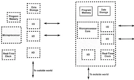
Figure 2.1 Microprocessor and Microcontroller Comparison... 5
Figure 4.1 Kano Model Diagram ... 15
Figure 4.2 Functional Design Example for Tool Interfaces... 18
Figure 4.3 ATmega328 Block Diagram ... 23
Figure 5.1 Ytterbium-doped (Nd:YVO4) Fiber Laser ... 28
Figure 5.2 Pulse Control Circuit and dSPACE Data Acquisition System ... 29
Figure 5.3 Functional Design for New System ... 31
Figure 5.4 Hardware Block Diagram with Corresponding Interfaces ... 33
Figure 6.1 Arduino Due ... 39
Figure 6.2 Breadboard Diagram ... 40
1
Chapter 1
Introduction and Background
1.1 Motivation
Since microcontrollers were first developed in the mid 1970’s, their use has continually spread and evolved. Today, many powerful and inexpensive development boards are readily available. Often, deciding which microcontroller development board to use for a specific task can be strenuous as a result of the seemingly limitless options. Determining the “best” choice involves matching up user requirements with the hardware and software capabilities.
Unlike many other mainstream hobbies or activities, the process surrounding creating a control system based off of a development board has no determined structure or order, regularly resulting in a long, time consuming procedure.
1.2 Research Goals
2 development board has unique specifications with varying input/ output (I/O) options, power requirements, central processing unit (CPU) speed, etc.
In order to reduce the time required to analyze and select the microcontroller
development board to be used, this research is focused on creating a systematic approach that can be followed to make a microcontroller development board-based control system. These
guidelines will be established such that the user can start from an idea stage, determine
requirements, and follow simple steps resulting in a microcontroller development board-based system that fulfills the generated system requirements.
1.3 Examples of Commercial Microcontroller Control Systems
Microcontrollers are capable of easily handling real-time data which leads to their popularity for control systems. Since microcontrollers are also inexpensive when produced in large quantities, they are commonly found in mass produced products involved in collecting and acting on real-time data. Commercial microcontroller control systems are found throughout many industries with some of the most commonly used found in the home as well as
automobiles. A thermostat is a microcontroller-based control system used in many products inside a home including ovens, refrigerators, freezers, coffee makers, and HVAC systems. As home automation is on the rise, many more microcontrollers are expected to infiltrate the home.
3 different parameters in vehicles at a frequency in excess of 1 MHz. These quick changes can greatly improve the efficiency of internal combustion engines.
1.4 Examples of Hobby Microcontroller Control Systems
Typically, hobby microcontroller control systems are created using a microcontroller development board. Microcontroller development boards are intended to help users gain
experience using new or unfamiliar microcontrollers, more specifically, the microprocessor core within the microcontroller. For their educational purposes, the development boards typically have many more features than commercial use microcontrollers. Since the commercial use microcontrollers were designed to complete one task only for the product’s lifetime, the required features can be task focused and ignore all unnecessary qualities. Having the full capability of the general-purpose microcontroller allows the user flexibility in the system they create.
4
Chapter 2
Historical Review
2.1 Differences between Microcontrollers and Microprocessors
A microprocessor, also called the central processing unit (CPU), is responsible for reading and acting on the instructional code supplied to it. The microprocessor takes in data from input devices and then, with a set of coded instructions stored in the attached memory, processes the input. The information that is passed to the microprocessor can be processed using logical or arithmetic operations. After the microprocessor has interpreted and acted on the inputs, the processed data can then move on to being stored in memory or it can be sent as an output. All of these post-processed data decisions are predetermined based off of the code.
Unlike a microprocessor, a microcontroller has almost all the necessary components for a system on the same chip. This includes memory, data storage, and I/O options with the
5 The microcontroller’s processor core is typically a refined derivative of a full
microprocessor 1. For this reason, microcontroller development is closely tied to the
advancement of microprocessors. The cause and effect of this fact will be discussed later on.
6
2.2 Origins of the Microprocessor
The first public announcement of a microprocessor came from Intel Corporation, U.S.A. in 1971 2. This came following a 1968 project with Japanese company Busicom, formerly
known as Nippon Calculating Machine Corporation. Busicom, like many other companies at the time, were attempting to gain success in the calculator industry. Recent advances in integrated circuits (IC) had led to dramatic reductions in the footprint of calculating machines.
Intel, a start-up company at the time, sought out to win the contract from Busicom to design the internal components of their calculator. Intel was one of few companies that envisioned the potential benefits of general purpose chips that would then be programmed to complete specific tasks 3. With initial resistance from Busicom, Intel had a four-chip set ready
for production. The Intel 4004, a “4-bit central processor logic chip,” was the world first “computer on a chip” 3.
2.2.1 Advancements
Although the invention of the microprocessor was revolutionary, the acceptance of its importance was sluggish initially. During the early period of doubt by the industry, Intel was continuing its development of microprocessors 3. By 1974 the Intel 8080 was introduced as a
faster, more efficient design. The 8080 had a performance advantage of approximately ten times over its predecessor, the Intel 8008. According to Intel’s Federico Faggin, one of the main creators of the microprocessor, “The 8080 really created the microprocessor market. The 4004 and the 8008 suggested it, but the 8080 made it real” 3.
Soon after the acceptance of the microprocessor’s benefits by the industry,
7 implement the new technology into their products to attempt to outdo their competition. Some early adopters of microprocessors were the calculator and watch industry. As shown by Intel and Busicom, microprocessors were able to greatly minimize the required size of a product. This led to “pocket calculators” and more advanced scientific calculators. Also, since microprocessors were able to keep accurate time that would not need a correction for years, watch makers produced lightweight, durable digital watches. The successes of the few companies that were able to blend in microprocessors to their products further solidified the opinions of some on where the market for microprocessors was headed.
Along with companies that aimed to add the microprocessor to their products, established businesses as well as start-up companies sought to create their own microprocessors. Some of the more successful ventures were those by Texas Instruments (TI), Motorola, and Intel 3.
Driven mainly by these three companies, the microprocessor market was ever changing due to new innovations.
2.3 Development of the Microcontroller
During the late 1970s, microprocessors were being implemented in automobiles.
8
2.3.1 Advancements
As is the case of the modified Motorola 6800, microcontrollers tend to be based off of microprocessor cores, meaning microcontrollers are simplified versions of their microprocessor predecessors. This is one reason why microcontroller advancements lag behind developments for microprocessors. Another reason involves the cost of microcontrollers. Since
microprocessors are cutting edge and designed for top performance, prices are greater when first introduced to the market and proceed to steadily drop. Over time, manufacturers are able to refine processes and reduce the physical size of the chip being produced. This is known as ‘shrink’ to silicon vendors 1. By this stage, research and development costs have been recovered
from selling the initial processors at a premium so lowered prices are now acceptable for the now older family of microprocessors/microcontrollers 1. These much cheaper microprocessor cores
are used in mass produced microcontrollers.
2.4 Development Platforms
9
2.4.1 Development Platform History
One of the first development platform devices was from Intel in 1973 and was called the Intellec 4-40 3. Other companies took notice after the increased sales that were attributed to the
hands-on experience and developed their own development systems. Development platforms continued to progress within the industry but had little outside interest. One feature that pushed the microcontroller development platform towards mainstream use was the development of EEPROM (Electrically Erasable Programmable Read-Only Memory). EEPROM allowed for a quick, inexpensive method for erasing memory on microcontrollers which enabled users to easily use a microcontroller for another application.
The next major milestone in development platforms was the introduction of open source hardware and software. One of the most well-known examples of open source is Arduino. Arduino, first introduced in 2005, has been a major factor in the increase in microcontroller development board usage. Being open source, hardware and software is free and can be used by anyone. This lowers costs dramatically as competitors enter the market. The lowered cost, as well as an extensive community, has pushed microcontroller development platforms more toward the “everyday person.”
2.4.2 State of the Art
10
2.5 Difficulties in Choosing the Appropriate Platform
11
Chapter 3
Research Objectives
After reviewing literature on microprocessor development board control systems and design, it is evident that a systematic guide to designing and implementing such a control system is not readily available. This is in contrast to many other types of control systems that utilize more expensive equipment that can easily exceed hundreds of dollars. For control systems that have relatively few I/O demands and require processing speeds no greater than 1 gigahertz (GHz), microprocessor development boards can be a simple and inexpensive solution.
12 To create the systematic guidelines, the system being designed must be further
13
Chapter 4
Systematic Design Process
In order to properly design any system, the needs of the end user must always be
considered. For most projects, the needs, or requirements, will almost always differ from those of another project. The uniqueness of each design is why identifying the requirements is so vital to the project’s success. The ability of the system’s designer to effectively gather the needs of the end user is crucial to the perceived success of the design. A design that fully satisfies the needs of the user will, for obvious reasons, be desired more than a design that does not fulfill their needs. Some questions to ask the end user to better understand the goals and requests of the new system include “What needs will the intended solution satisfy?”, “What properties must it have?”, and “What properties must it not have?” 4. Answering these questions can lead to a list
of needs for the system.
4.1 Classifying and Prioritizing Needs
14 which influence the satisfaction of the customer when met 5. One of these three types of
requirements is referred to as “must-be” requirements 6. The must-be requirements are those that
the end-user expects to be present in the system. If these basic criteria are not met, the user would be dissatisfied. When the must-be requirements are met however, the satisfaction of the user is not noticeably changed and all that can be noted is that the user is “not dissatisfied” 5.
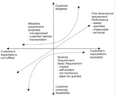
This can easily be seen using the Kano model diagram as shown in Figure 4.1. The vertical axis shows the customer’s satisfaction while the horizontal axis is related to the level of fulfilment a certain system quality is perceived to have by the customer. In Figure 4.1, the must-be
requirements can never provide the customer with a satisfaction level greater than neutral even if the expectations of the customer are greatly surpassed. Figure 4.1 also demonstrates how the customer’s satisfaction quickly diminishes if these basic requirements are not met.
Due to the lack of a positive response when met, must be requirements can sometimes be overlooked or forgotten about. This can pose problems when attempting to establish system requirements and for this reason, it is important to be thorough when examining the intended system’s functionality.
Another type of a Kano model requirement is referred to as “one-dimensional” 6. A
one-dimensional requirement is one in which the user’s satisfaction level is proportional to the level of functionality of the feature. This direct proportionality stems from the fact that
one-dimensional requirements are generally explicitly stated by the customer. Since this aspect of the system was stated as a requirement, customers’ satisfaction will depend on the level of its fulfilment.
15 customer’s perceived value of the system if present but has no negative effect if it is not. An attractive requirement has a large effect on a customer’s satisfaction if an attractive feature is included in the product or service. Since attractive requirements are not openly stated by a customer, they are therefore obviously not expected to be included in the product, hence they have no negative effects if they are not included. If present however, the customer’s satisfaction greatly increases more so than is observed when a one-dimensional feature is included.
Figure 4.1: Kano Model Diagram 6.
16 customers want out of a product. Companies that do so are attempting to achieve the ultimate goal of increasing customer satisfaction which leads to a larger market share. Since this design process is assumed to be completed by the end user for themselves or a small group of others, designing to satisfy potentially thousands of third party users is not required. Therefore, end users can use the early stages of the Kano model development to aid in forming a more complete list of requirements as well as prioritize them for the selection process. Prioritization will allow for a more structured approach when making a decision between two microcontroller
development boards with similar functional capabilities.
4.2 System Requirements
After understanding the needs of the system being designed, solutions to these needs can now be considered. One common method for designing a system is known as conceptual design. Conceptual design involves establishing requirements from literature study or end user
interviews. The requirements can then be prioritized based on the needs of the application. “Functions” can then be produced such that they satisfy the prioritized requirements list. The generated functions need to be first described in nonconcrete terms and then fulfilled by a physical device or apparatus 7. Combining one physical solution for every function creates a
completed design for the system. Multiple designs can be generated by selecting varying combinations of function solutions.
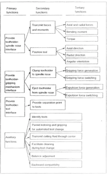
17 Functional design of a system involves creating functions of varying system importance to the system in order to fulfill the previously generated requirements list. The list of functions will be comprised of groups indicating the functional importance of each entry. The main functions will be designated as the primary functions. Primary functions can be comprised of multiple subfunctions that, collectively, complete the goal of the main function. These subfunctions, known as secondary and tertiary functions, are often functions that complete a feature of the primary functions. For example, if a primary function of a ratchet is to provide a gripping mechanism interface between the ratchet and the socket, two secondary functions would be a way to attach the socket to the ratchet as well as a way to remove the socket. As previously stated, it is important to keep the functional design of the system free of preconceived solutions as a way to avoid limitations to new ideas.
Figure 4.2 is an example of functional design. For the example, the functional design of machine tool interfaces for high-speed machining was being considered. The auxiliary functions section denotes functions that do not fit into one of the functional group trees but are obviously still integral to the system.
19 When using progressive design methodology, components are created in a sequential process. One component is created and then the system is progressed further by adding another component. The order in which components are generated is based on the requirements list. Requirements that are deemed the most important must be satisfied first with those of lesser importance following.
4.2.1 Input/Output (I/O) Capabilities
Once the design is established, certain qualities that must be achieved by the
microcontroller development board can be examined. One of the first step to do so involves creating a hardware block diagram for the design. The hardware block diagram will include all necessary interfaces between the microcontroller development board and all other hardware. In addition, the type of interface, as well as the quantity, must also be included. Knowing what interface is required for the hardware is a crucial step. Microcontroller development boards have numerous configurations with vastly different input and output options. Some communication hardware requires USB communication while others need Inter-Integrated Circuit (I2C, also
frequently written as I2C), Serial Peripheral Interface (SPI), or Universal Asynchronous Receiver/ Transmitter (UART) interfaces. Aside from USB connections, most of the interfaces are found as pins on a microcontroller development board. To find which pins are capable of certain communication features the board’s documentation, often included with purchase or online, can be consulted.
20 pins that are assigned as either an input or an output by the user code. GPIO pins typically comprise most of the pins available on a microcontroller development board due to their frequent use and adaptability. PWM and analog I/O typically comprise a small fraction of the total pins as a result.
After the hardware block diagram has been generated with the required interfaces, a minimum number of I/O pins can be established. At this stage in development board research, all microcontroller development boards that do not meet the minimum requirements for pins, communication pins or otherwise, can be disregarded.
4.2.2 Power Considerations
Another selection process that can be completed after generating the hardware block diagram involves voltage requirements for external devices connected to a microcontroller development board. Most development boards supply either 5V or 3.3V to its pins. Knowing the voltage needed to properly power an external device is crucial for its longevity and
functionality. If too few volts are supplied, the device will not function while too high of a voltage would cause damage to the device. Depending on what voltage is required by the components to be used, some microcontroller development boards can be removed from consideration. Although, if not all devices being used need the same voltage level, simple additions can ensure most devices can be used by the same board. One such option is a level shifter. A logic-level shifter can easily be found, especially bi-directional versions for 3.3V and 5.5V applications.
21 use an external power source for components particularly when numerous components are being used to avoid unnecessary stress on the microcontroller development board 8.
4.2.3 Microprocessor Core
The microprocessor core of a microcontroller development board is the next category of interest. The microprocessor core is typically considered as the main performance indicator for a development board. Those new to the process consider the frequency of the microprocessor as a clear-cut way to differentiate the superior development board. This is true to a certain extent as the processor’s clock speed, measured in some form of hertz, is a major indicator of performance but is not the sole aspect to consider. Unlike systems that utilize an advanced microprocessor, such as computers, microcontrollers have far less complicated architectures which makes the expected performance very near linear when compared to clock speed. However, there are varying architectures that are used for microcontrollers that possess certain advantages and disadvantages depending on the system being used. This is beyond the scope of these guidelines but can be explored when more knowledge is gained. If selecting a microcontroller based on architecture is pursued, the result can be a system that is optimized to complete a specified task with the minimum microprocessor core required generally resulting in lowered power
requirements and a smaller hardware footprint.
22 quadcopter/ drone. In order to maintain controlled flight, sensor data must be processed quickly. If a microcontroller with a lesser clock rate were to be used, a delayed response to one of the motors could result in a crash.
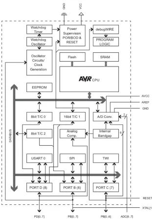
23 Figure 4.3: ATmega328 Block Diagram 9
4.2.4 Memory
24 stored until that action is complete 10. Another memory category, data memory, is significantly
larger than the register file and it stores data used by the CPU. Similar to the register file, data memory can be stored temporarily for near immediate use but also has the capability of being recalled much later on in the process after numerous operations. Instruction memory is the final memory category of note and, as can be assumed by the name, is where instructions can be retrieved by the CPU. Both the data and instruction memory are relatively larger than the register file and therefore are typically external memory. For microcontrollers, both of these memory types are integrated into the microcontroller chip, typical of a microcontroller’s inclusive design.
Further categorization of memory types includes volatile and non-volatile memory. Volatile memory is only retained as long as the system remains powered on while non-volatile memory is stored for future use even if power is lost. Volatile memory is much faster than its counterpart and is thus used for data memory. Non-volatile memory could be used for data memory, but the performance of the system would be greatly decreased.
Volatile memory is synonymous with Random Access Memory (RAM). Two types of RAM are most common in systems, Static RAM (SRAM) and Dynamic RAM (DRAM). For microcontrollers, SRAM is the typical choice for RAM. DRAM is capable of storing more data in the same amount of physical space as SRAM but has significant drawbacks. DRAM is slower than SRAM and also uses capacitors to store data but must be frequently recharged as to not lose the stored data 10. Solutions to this problem do exist and are frequently used in other applications
25 For non-volatile memory, microcontrollers typically use multiple types of Read Only Memories (ROMs). Electrically Erasable and Programmable ROM (EEPROM) is frequently used for data memory. EEPROMs have a self-explanatory title meaning that they are fully capable of writing and erasing data using changes in voltage. The ability for EEPROM to erase data with relative ease is why microcontroller development boards utilize microcontrollers with this type of memory. One disadvantage however is that EEPROMs have a limited number of write cycles meaning eventual loss of write/erase capabilities. This disadvantage is why EEPROMs are typically only used for long term storage but even then, the likelihood of ever reaching the number of cycles required, approximately 100,000, is minimal.
A variation of EEPROM that is primarily used for program/instruction memory is known as Flash EEPROM. Flash EEPROM, typically referred to as only Flash, can only erase large blocks or the entire memory at once 10. Unlike EEPROMs that can erase down to the byte level,
Flash memory is not suited for data memory applications and, as mentioned, is used for program memory. Not erasing individual bytes of data simplifies the design, in turn reducing the price.
26 functions for sections of code that are identical or very similar. Also, signed values ranging from -128 to 127 or unsigned values from 0 to 255 can use ‘char’ or ‘short’ datatypes respectively to use only one byte each. Not using this datatype would increase SRAM usage by double (short, uint16_t) or quadruple (long, uint32_t) which can be a significant issue if many values are needed.
Another way to reduce SRAM memory usage would be, if using Arduino IDE, moving the data to the program memory (Flash) with the PROGMEM command. This allows for the data to be called from Flash and will not be stored in SRAM. Similarly, EEPROM can be used to store constant values, such as large tables, to avoid unnecessary SRAM usage. With all of these factors in mind, SRAM expansion is available as an external device. If this is to be needed, an increased number of I/O pins would be required which could have an effect on the
development board selection.
27
Chapter 5
Case Study
In an effort to test the microcontroller development board selection guide generated in Chapter 4, a case study was conducted. For the study, a development board was chosen to replace an existing control system used in the Intricate Laser Processing Lab at North Carolina State University.
5.1 Current System Design
The current system is used to control a single mode Ytterbium-doped (Nd:YVO4) fiber
laser made by IPG Photonics. Two main ways to control the laser pulses exist, one being from external computer programs and the other from a custom pulse control circuit. The following is a description of the control system as defined in Nilesh Rajule’s dissertation (2014) Laser Synthesis and Characterization of Copper-Single Walled Carbon Nanotubes Nanocomposites:
28
Simulink is used to create different operating schemes to synchronize laser control and the motion of the motors. This configuration is able to provide temporal pulse control of laser on millisecond time scale. However, it fails to control laser on microsecond time scale due to limitations of its sampling rates.
A pulse control circuit was designed and developed in the lab to overcome the problem of pulse control of the laser on a microsecond time scales. This pulse control circuit offers many single pulse and multiple pulse configurations on microsecond as well as on millisecond time scale. This circuit takes input from a EZ FG-7002C function generator and process it through a series of timers and gates to deliver output pulses. Numerous pulse configurations are achieved by combinations of input frequency, total process time, primary pulse duration, and secondary pulse duration. (p. 37-38) 11
29 Figure 5.2:Pulse Control Circuit and dSPACE Data Acquisition System 11
5.2 Requirements for the New System
Dr. Jay Tu, the professor in charge of the Laser Manufacturing Lab at NC State
University, expressed a desire to replace the Pulse Control Circuit, as seen in Figure 5.2, with a system based on a microcontroller development board. The requirements of the system were discussed and analyzed using the Kano Model. It was clear that a “must-be” requirement for the system was that it should be fully capable of replacing its predecessor in terms of operations and capabilities. This was never explicitly said but made obvious by the wish for a new, upgraded system that could accomplish the same tasks. Reliability of the system was also stressed as it is important for the system to function properly and accurately when needed.
It was also made clear that the new system should be flexible and more configurable to allow for more exact pulse control as well as support any future changes made to the laser system. This requirement would fall into the categorization of “one-dimensional” since
30 desired for pulses included fully programable pulse durations, milliseconds or microseconds, for any pulse either in the form of a single pulse or groups. The current system allows for some control over the pulse durations, but there is a limited amount of options to choose from. Also, the system allows for differing durations between the first pulse and the remaining pulses, but all of the remaining pulse durations must be the same value. A requirement for the new system is to allow for full customization of any pulse. Communication protocols that the microcontroller development board supports will also be considered. The number of potential connections greatly effects the ability for future expansion or remodeling and therefore is viewed as a one-dimensional requirement as well.
One final one-dimensional requirement would be the price of the microcontroller development board and any other required hardware. The price of each system solution can be compared to the other solutions. The least expensive option is considered the most desirable.
While gathering information for generating the requirements list, an “attractive”
requirement was discovered. A microcontroller development board with more advanced features such as Wi-Fi or Bluetooth connectivity would be perceived as a “bonus” and greatly satisfy the users. This would allow for remote operation from within the lab as well as more possibilities for future alterations or expansions.
5.3 Microcontroller Development Board Selection
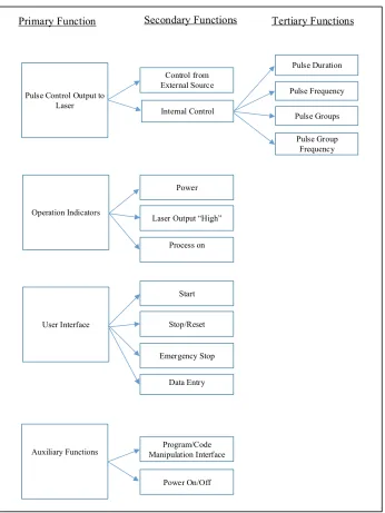
31 Figure 5.3: Functional Design for New System
32 is powered on, when the output signal is high (i.e. the laser is firing), as well as when the process of the pulse or pulse group is ongoing. To begin the process, there needs be a method for data entry to allow for customizing the pulse or pulse group properties. Correspondingly, there must be a way in which to stop the process and/or reset it to where the process can begin again. For safety purposes, and emergency stop is required. Finally, there should be a method to make changes to the program code without removing the development board from the system as well as a way to power off and on the system.
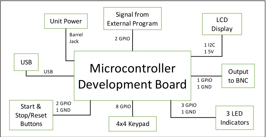
Now that the functional design has been created, the progressive design methodology can be used to generate a system. Using this, a hardware block diagram can be generated with all interfaces between the hardware listed as well as seen in Figure 5.4. To satisfy the functional requirements, the design of the replacement system included an output via a BNC port which transmits the pulse signal to the laser. To accommodate the external program commands, two inputs in the form of BNC connectors receive signals from the dSpace system. Together, with the signal output to the laser, three general purpose I/O pins are required for pulse control as well as a ground connection for all three.
33 breadboard must be used since there are very few ground connections on all microcontroller development boards. The use of the breadboard for ground applies to all components being discussed in the hardware block diagram.
A 4x4 keypad was selected as a way to input user data. The matrix keypad only requires 8 GPIO pins, one for each row and column. This allows for any keypress to be identified based on a signal from one row and one column, corresponding to one key on the keypad. A start or stop/reset button can be configured in multiple ways. If the microcontroller development board has pull-up resistors built in, the buttons will need one GPIO and a ground connection. A much more common approach is to utilize a breadboard with 5V and ground connections with a GPIO pin capable of reading the state of the button. Using either method, only one GPIO is needed per button resulting in two pins needed for this system.
Figure 5.4: Hardware Block Diagram with Corresponding Interfaces
Microcontroller
Development Board
Start & Stop/Reset Buttons USBUnit Power External ProgramSignal from
4x4 Keypad LCD Display Output to BNC 8 GPIO 3 LED Indicators 2 GPIO 1 GND USB Barrel
Jack 2 GPIO
34 Also involved in data entry, an LCD display is used to confirm and present inputs from the keypad. The LCD screen requires use of an I2C connection which consists of two pins specially marked on the boards or in their documentation. To power the LCD, a 5V and ground connection are needed and can be done using a breadboard. In order to connect the
microcontroller board to computer to upload code, a USB is needed. Microcontroller
development boards tend to have USB connections although USB types will vary. Finally, a connection is needed to supply power to the development board. This can usually be done in a variety of methods but predominantly via a barrel jack connection or through a USB connection. For this system, a barrel jack is preferred since the USB port should remain available for
connection to a computer for coding purposes.
From the functional design, an emergency stop is required for the system. In this system, as is typically done, the emergency stop is connected to the power supply before the power reaches the microcontroller development board. When pressed, the development board can no longer be powered on. There is an alternative option however for use with a microcontroller-based system. Microcontrollers contain interrupt capabilities that allow for alternate
programming to be done if an event is triggered. In the case of an emergency stop button, an interrupt could be established to suspend operation if a pin changes state (button press). This process could be suitable for emergency stops in lower risk applications.
35 Table 5.1: Interface Type and Quantity for the System
Power considerations for this system should not much impact on the selection of the development board. Only the LCD display requires a specific voltage for operation while all other components can operate with either 5V or 3.3V. As noted in the previous chapter, it is recommended to use an external power source for components. This can be done by creating a regulated power supply circuit which, for this specific case, can be done with relative ease due to the need of an emergency stop. Two power supplies can be created to power a 5V and 3.3V breadboard for ease of use with components and any future additions.
The microprocessor core within the development board must be capable of processing data quickly enough to ensure signals to and from pins can be changed on a microsecond scale. For this system, pins must be switched from their current state, high or low, to the opposite state with the minimum time between being approximately 20 microseconds. A clock speed of one MHz corresponds to a clock cycle occurring every microsecond, but it should be remembered that one clock cycle does not necessarily represent one line of code being acted on. For this application, the commands do not require intensive data processing so lower end processor speeds, 8 to 16 MHz, should be more than enough for the system.
Interface Type
Minimum
Required
GPIO 16
USB 1
Barrel Jack 1
I2C 1
5V 1*
GND 1*
36 The memory requirements of the system as it is currently designed would be rather low since all tasks are relatively basic. The program memory should be minimal with user input prompts having some size due to the string data type. As stated earlier, the current program is not data processing intensive meaning having significant SRAM is not needed. With any future additions and expansions to the system, both the Flash and SRAM requirements would increase so an overestimate is needed for the initial design.
In order to fulfil the must be requirements as stated in the requirements above, the new microcontroller development board-based system must be able to fully replace the previous version. One of the easiest methods for quickly narrowing the search is to eliminate boards that do not have the necessary number of interfaces. For this system, 16 GPIOs are needed along with one I2C, these interfaces being the most common to vary between boards. Meeting these needs is fairly common for microcontroller development boards but once the one-dimensional requirement of expandability is factored in the number quickly falls. To allow for significant future expansion, approximately 30 GPIO pins and numerous communication protocol options should be present for interfacing.
37 EEPROM. The Due has an 84 MHz processor speed, 512 kB Flash, 96 kB SRAM, and no EEPROM.
The microcontroller development board that best satisfies the requirements is the Arduino Due. When considering the expandability of each board, it is clear that the Due’s superior
38
Chapter 6
Results and Discussion
6.1 Fulfilment of Requirements
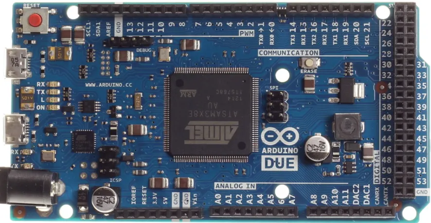
The process of choosing a microcontroller development board based on the requirements and steps demonstrated previously yielded the selection of an Arduino Due. The Due, shown in Figure 6.1, was easily able to fulfill the requirements involving the quantity of pins. The board has all interfaces and pins required to replace the old system and also contains many more I/O and interfacing options. This should allow for the Arduino Due based system to be expandable for many future needs. Although the Due satisfied the must-be and one-dimensional
39 Figure 6.1: Arduino Due 12
40 Figure 6.2: Breadboard Diagram
In Figure 6.2, the three LED indicators are shown. All three LEDs require the use of a 220W resistors which are all connected to the Ground rail. The red LED is a simple indicator for whether or not the system is powered on and leads to pin 44 on the Due. The yellow LED, digital pin 46, displays if a process in ongoing for the system. Here, a process represents the time between when the first pulse is generated and all, if any, subsequent signals are output to the BNC connection to the laser. The final LED is an indicator for when a pulse signal is sent to the laser and is controlled via pin 48 on the Due. This of course represents a time during which the laser is firing a pulse.
41 Finally, a ground connection is used for the BNC output, but additional ground connections are available on the Due if desired.
Figure 6.3 shows the LCD display and the 4x4 matrix keypad. The keypad used for testing is a membrane keypad with the row inputs being connected to pins 22, 24, 26, and 28 and the columns connects to pins 23, 25, 27, and 29. The Arduino library “keypad.h” is used which greatly simplifies the commands to acquire a keystroke when pressed. The LCD shown in Figure 6.3 displays one of a few prompts that guides the user through establishing pulse
characteristics for a given process. The prompts lead to generating the number of pulse groups, pulses per group, pulse frequency, pulse group frequency, and the individual pulse durations. From here, the start button can be pressed to begin the pulse control and the stop/reset button can be used to return to the start stage again if the pulse settings are to be used again.
42 For the output of the pulse signal, pin 33 on the Arduino Due is used. With the generated array of pulse durations, along with other input data, direct port manipulation is used to allow for state changes to occur faster while also being much more accurate. For testing, pin 33 and a ground wire were connected to a Tektronix MSO2024 Oscilloscope for measurement.
For a finalized design, many aspects of the described system have flexibility in
positioning and methods thanks in part to the numerous amount of GPIO pins available for use. As per the requirements, future expansion of system capabilities is made simple by the
input/output options as well as the memory size. For example, the code used for testing used just 30,568 bytes of program storage space out of the available 524,288, or approximately 5%.
6.2 Pulse Control Comparison
43 Table 6.1: First Pulse Duration Positional Setting
Table 6.2: Second Pulse Duration Positional Setting
Position Millisecond Duration Microsecond Duration
1
2.53 ms
27.2 µ
2
2.7
28.9
3
2.8
30.1
4
2.9
31.1
5
3.0
32.0
6
3.1
33.0
7
1.3
13.9
8
1.4
14.8
9
1.5
15.9
10
1.6
16.7
11
1.7
18.7
12
2.0
21.3
13
2.1
22.2
14
9.8
104.0
15
2.4
25.8
16
2.5
26.2
17
18.1
139.0
First Pulse Duration
Position Microsecond Duration (µs)
1 8.8 2 6.8 3 9.0 4 9.8 5 10.6 6 Unlimited
44 Table 6.3: Process Time Positional Setting
To test the Arduino Due’s capabilities of replacing the previous system, tests were conducted to explore pulse control capabilities. A program was generated using the Arduino Integrated Development Environment (IDE), a tool to allow for easier coding and uploading to a microcontroller board. Polling was used to test keypad entry as well as the LCD display. Since Arduino IDE is a simplified version of C++, Arduino libraries were included for quick
implementation of the keypad and LCD. Libraries are sections of code that can be included that create simplified commands for use with components.
When prompted, the user can enter the number of desired pulses per group, the number of pulse groups, the frequency of the pulses, the frequency of the pulse groups, and the duration of all pulses. This allowed for full control over the pulse settings, a one-dimensional requirement for the system. For the test, multiple pulse settings were used. Tables 6.4, 6.5, 6.6, and 6.7 contain the results for the pulse duration from the test as recorded by the Tektronix MSO2024 Oscilloscope.
Position Millisecond Duration (ms) Microsecond Duration (µs) 1 Unlimited Unlimited
2 18.00 1510
3 17.00 1370
4 14.80 1200
5 13.20 1070
6 11.60 948
7 9.68 788
8 8.16 654
9 5.00 452
10 4.52 364
11 3.46 278
45 Table 6.4: Single Pulse Duration Test
Table 6.5: Two Groups of Two Pulses Duration Test
Table 6.6: Two Groups of Three Pulses Duration Test Input Actual
20 22.4
30 32.4
50 52.4
1000 1002.4
Duration in Micrseconds
Single Pulse
Input Actual
1,1 30 32.4
1,2 20 22.4
2,1 30 32.4
2,2 20 22.4
2 Groups of 2 Pulses
Duration in microseconds Pulse Group,
Pulse
Input Actual
1,1 30 32.4
1,2 20 22.4
1,3 20 22.4
2,1 30 32.4
2,2 20 22.4
2,3 20 22.4
2 Groups of 3 Pulses
Pulse Group,Pulse
46 Table 6.7: Three Groups of Three Pulses Duration Test
As evident in the results, a consistent error of 2.4 microseconds was present. After researching Arduino documentation, it was found that the Arduino IDE command ‘DigitalWrite’ results in a delay between 2 to 5 microseconds depending on which microcontroller board is being used. A solution to this delay is known as direct port manipulation. This bypasses the simplified Arduino code and uses lower-level communication to quickly alter the state of the pins. Board specific documentation must be consulted to find the pinout of the microcontroller so that port locations are known. Once implemented, the 2.4 microsecond error was removed and consistently provided accurate microsecond durations down to two decimal places. These results have shown that the Arduino Due is a capable microcontroller development board to replace the previous pulse control system, therefore, fulfilling all requirements.
Input Actual
1,1 30 32.4
1,2 20 22.4
1,3 20 22.4
2,1 30 32.4
2,2 20 22.4
2,3 20 22.4
3,1 30 32.4
3,2 20 22.4
3,3 20 22.4
3 Groups of 3 Pulses
Pulse Group,
47
Chapter 7
Summary
7.1 Conclusion
By completing a case study, it was shown that the designed systematic approach to selecting an appropriate microcontroller development board to be used in a control system was feasible. By following the procedure, a system can be designed by using requirements,
functional designs, and hardware block diagrams. This, combined with information provided on determining the necessary microprocessor core speed and memory size, can generate a list of required specifications for the microcontroller development board. With these specifications, a microcontroller development board can be selected by the user.
7.2 Future Work
48 As for the system designed in the included case study, completion of the system would allow for comprehensive testing on its abilities to meet the provided requirements. A method for testing expandability for future additions to the system would be to generate multiple mock systems to add to the development board. This would test for any strains placed on the processor and memory of the system.
7.2.1 Updating for Future Advancements
49 REFERENCES
1. Berger AS. Embedded Systems Design. Lawrence, Kansas: CMP Books; 2002.
2. W. Aspray. The Intel 4004 Microprocessor: What Constituted Invention? IEEE Annals of the History of Computing. 1997;19(3):4-15. doi: 10.1109/85.601727.
3. Malone MS (S, 1954-. The Microprocessor: A Biography. Santa Clara, CA: TELOS; 1995. http://www2.lib.ncsu.edu/catalog/record/UNCb2801076.
4. Ferguson S. Identifying Customer Needs and Generating a Requirements List. PowerPoint slides. 2017.
5. Matzler K, Hinterhuber HH. How to make product development projects more successful by integrating Kano's model of customer satisfaction into quality function
deployment. Technovation. 1998;18(1):25-38.
6. Berger C, Blauth R, Boger D, et al. Kano's Method for Understanding Customer-Defined Quality. Center for Quality of Management Journal. 1993;2(4).
7. Bossmanns B, Tu JF. Conceptual Design of Machine Tool Interfaces for High-Speed Machining. Journal of Manufacturing Processes. 2002;4(1):16-27.
8. Bavishi A. How to Choose the Best Development Kit. Predictable Designs Web
site. https://predictabledesigns.com/how-to-choose-the-best-development-kit-the-ultimate-guide-for-beginners/. Updated 2017.
9. Barrett SF. Arduino Microcontroller Processing for Everyone! Third ed. Morgan & Claypool; 2013.
10. Gridling G, Weiss B. Introduction to Microcontrollers. 1.4th ed. Vienna University of
Technology: Institute of Computer Engineering - Embedded Computing Systems Group; 2007. 11. Rajule N. Laser Synthesis and Characterization of Copper-Single Walled Carbon Nanotubes
Nanocomposites. North Carolina State University; 2014.