R E S E A R C H
Open Access
Research on network coding aware energy
efficient routing for wireless sensor networks
Xing Shao
1,2*, Cuixiang Wang
1,2and Jun Gao
1Abstract
Wireless sensor nodes in wireless sensor networks are generally battery powered and it is usually hard to change their batteries. Therefore, energy saving has always been the basic critical problem of wireless sensor networks. In recent years, network coding has become a promising technology to improve network throughput, reduce transmission number, and save energy, which has great potential to solve the energy efficiency problem of wireless sensor networks. In addition, some network coding aware routings have been proposed. However, the network coding condition of existing network coding aware routings may experience the problem of false-coding effect in some scenarios, and usually neglect node energy, which greatly influences the energy efficiency performance. Therefore, existing network coding aware routings are not suitable for wireless sensor networks. This paper proposes network coding aware energy efficient routing (NAER) for wireless sensor networks. In NAER, universal network coding condition is presented and proved to avoid false-coding problem. Besides, combined with the coverage control and topology control mechanism at lower layer, cross layer coding opportunity discover mechanism is presented to increase coding opportunities. In addition, a network coding aware energy efficient routing metric (NERM) is presented, which takes coding opportunity, node energy, and link quality into account jointly. Simulation results demonstrate that NAER improves the accuracy of coding discovery mechanism, increases the number of coding opportunities, saves node’s energy consumption, and prolongs network lifetime.
Keywords:Network coding aware, Energy efficient, Routing algorithm, Wireless sensor networks
1 Introduction
In past decades, wireless sensor networks (WSNs) [1, 2] have drawn great attention from research filed due to its potential in many important applications, e.g., hazardous environment monitoring, target tracking, biomedical health monitoring, and so on. However, sensor nodes in WSNs are generally powered by batteries, and it is usu-ally hard for administrator to replace their batteries, due to the constraints of numerous number of nodes and the network deployment environment. Therefore, the energy saving [3,4] is a basic and critical issue for wireless sen-sor networks, and the design of energy-efficient routing algorithm [5–8] is an important aspect.
In 2000, Ahlswede et al. [9] proposed the concept of “network coding.”Network coding allows the intermediate nodes of the network to encode the received packets, sub-verting the opinion of traditional information theory that
the encoding to the received packets at intermediate nodes brings no gain. Li et al. [10] proved that the rate of multicast exploiting network coding can reach the upper bound of the maximum flow minimum cut theory. Spe-cially, the network coding in the wireless environment [11, 12] can make full use of the open characteristics of the wireless channel, reduce the number of data transmissions and improve the network throughput, which is very suit-able for wireless sensor networks.
To illustrate the advantage of network coding in wireless environment versus traditional store forward manner, take the scenario in Fig.1as an example. In Fig.1, node 1 and 3 want to exchange a pair of packets via node 2. Using store forward manner, the exchange process will require four transmissions as Fig. 1a. However, using network coding manner, after having received P1and P2 respect-ively from node 1 and node 3, node 2 performs network coding operation on P1 and P2 and then sends out the coded packet P1⊕P2. Due to the broadcast nature of wireless channel, both node 1 and 3 will receive P1⊕P2. Then node 1 can obtain the native packet P2 through * Correspondence:[email protected]
1Yancheng Institute of Technology, College of Information Engineering, Yancheng 224051, China
2Arizona State University, Ira A. Fulton Schools of Engineering, Phoenix 85281, USA
calculation ofP1⊕(P1⊕P2) =P2, and node 3 can obtain
P1throughP2⊕(P1⊕P2) =P1. It is obvious from Fig.1b that the number of transmissions using network coding is reduced to three compared with the store-forward manner shown in Fig.1a.
Due to the advantages of network coding in reducing data transmission and improving throughput, some network coding-based routings for wireless multi-hop network have emerged [13–15]. The network coding exploited in wireless multi-hop network routing can be divided into two categories: inter-flow network coding and intra-flow network coding according to the packets participating in network coding belongs to single flow or multiple flow [9]. Intra-flow network coding gener-ally uses random linear network coding to solve trans-mission reliability problem, while inter-flow network coding, which generally performs XOR operation, ex-ploits the broadcast nature of the wireless channel to reduce the number of data transmission and is suitable for energy-efficient routing. Therefore, this paper fo-cuses on the research of inter-flow network coding-based routing for wireless sensor networks. Besides, inter-flow network coding-based routing is also com-monly known as coding aware routing.
Katti et al. [16] proposed coding opportunity architecture (COPE) to solve unicast problem using network coding in wireless mesh networks and presented classical “one hop”
coding structures. Ni et al. [17] proposed routing with opportunistically coded exchanges (ROCX). ROCX can proactively change routes according to “one hop” coding structures to create more coding opportunities. Le et al. [18] presented distributed coding aware routing (DCAR), which extends the range of coding structure in COPE to multi-hop and increases coding opportunities. Guo et al. [19] investigated the failure decoding problem according to the network coding condition of DCAR in some scenarios and presented some improvement strategies. Peng [20] and Hou [21] proposed the interference and coding aware routing, which jointly consider network coding and wireless interference.
However, these proposed network coding aware rout-ings mentioned above do not analyze the network coding condition failure problem in depth and do not present the network coding condition that can guarantee the decod-able of coded packets. In addition, the node energy con-sumption and network lifetime are not considered by these routings. Therefore, existing network coding aware routings are not suitable for wireless sensor networks. In this paper, a network coding aware energy efficient routing (NAER) for wireless sensor networks is proposed. The contribution of this paper includes:
Analyzing the network coding failure problem in existing network coding aware routings, this paper proposes and proves universal sufficient and necessary network coding
condition, to improve the accuracy of coding opportunity discovery;
Based on cross layer technique, coding opportunity discovery combined with coverage control and topology control is presented to increase the number of potential coding opportunities.
A comprehensive routing metric, called network coding energy efficient routing metric (NERM), is presented, which jointly considers network coding opportunities, node en-ergy, and link quality.
This paper is organized as follows: Section 2 describes the key design methods of NAER and details information of the experiments. The related works and motivations are presented in Section3. Section4gives the detailed design of NAER routing algorithm. Simulation details and per-formance analysis are presented in Section 5. Section 6 gives the discussion on the design of NAER and experi-mental results. Section7concludes this paper.
2 Methods/experimental
The aim of this paper is to apply the network coding aware routing in wireless sensor networks to improve the energy efficiency of transmission in wireless sensor networks and prolong the network lifetime of wireless sensor networks. To solve this problem, NAER is proposed. The design of NAER includes three aspects: network coding condition definition, coding opportunity discovery algorithm design, and routing metric design. After analyzing the network coding condition failure problem in existing routings, this paper presents universal network coding condition to avoid decoding failure problem. In addition, based on universal network coding condition, this paper pro-poses the network coding opportunity discovery algo-rithm through cross layer interacting with coverage control and topology control to further increase net-work coding opportunities. Finally, a comprehensive routing metric, which jointly considers network coding opportunities, node energy, and link quality, is designed for NAER to reflect the quality of the discovered path.
To analyze the performance of NAER, extensive simula-tions are carried out on Network Simulator 2 (NS2). The simulations consider two scenarios, grid network without cross layer interaction and random network with cross layer interaction. Simulation results confirm that NAER can increase network coding opportunities significantly and prolong the network lifetime of WSNs.
3 Related works and motivations
Currently, some network coding-based routings for wireless multi-hop network have been proposed. And the key tech-nologies of these routings will be analyzed in this section.
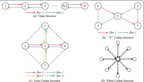
Sachin et al. [16] introduced network coding into the unicast in wireless multi-hop network, and proposed the routing framework COPE. In COPE, four classical
coding structures (chain structure, “X” structure, cross structure, wheel structure) that exist network coding op-portunities are discussed as in Fig. 2. Specially, the dashed line in Fig.2 means that the node at one end of the dashed line can overhear the packets sent by the node at the other end of the dashed line through the open wireless channel. However, COPE passively dis-covers the network coding opportunities according to the classical coding structure in established routings. In addition, the coding structures in COPE are limited within the one hop range of the coding nodes.
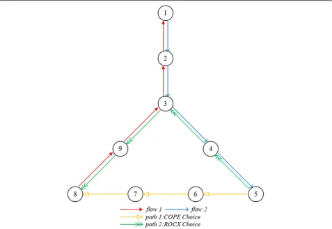
Ni et al. [17] proposed the concept of “Coding Aware” and ROCX, which combines route discovery with coding opportunity discovery to find path with coding opportunities as routing. Take the scenario in Fig. 3 as an example to explain the principle of cod-ing aware routcod-ing. In Fig. 3, there are two flows ini-tially, flow 1:8 → 1, flow 2:1 → 5, and their paths are illustrated in Fig. 3. Then, 5 wants to send packets to 8. Using COPE, 8 will choose the shortest path, path 1 as the routing, while path 2 will be chosen as rout-ing by ROCX, since there exist codrout-ing opportunities at node 2, 3, 4, 9 using path 2. Therefore, ROCX ac-tively discovers the routing with coding opportunities, and increases the number of coding opportunities. However, ROCX uses one hop coding structures to discover coding opportunities as in COPE.
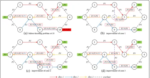
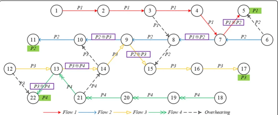
Le et al. [18] proposed distributed code aware routing (DCAR). DCAR presented multi-hop network coding condition for two flows intersecting at one intermediate node, which expands range of the coding structure from one hop to multi-hop. The scenario in Fig. 4 depicts an example of coding structure with multi-hop range. In Fig. 4, flow 1 and flow 2 intersects at node 3. Then, 11 can overhear packets from 1, and 5 can overhear packet form 8. If node 3 codes the packets offlow 1andflow 2, 6 and 11 can obtain their native packet respectively. It is obvious from Fig. 4 that the decoding nodes and over-hearing nodes are all two hops away from the coding node 3, which expands the range of coding structure compared with COPE. Although DCAR broadens the scope of coding structures and improves the ability of routing to discover more coding opportunities, the de-coding according to the multi-hop network de-coding con-dition may be failure (false-coding effect) in some scenarios as given in Fig.5.
Guo et al. [19] investigated the decoding failure scenarios according to the network coding condition in DCAR as given in Fig. 5. In Fig. 5a, there are three flows, flow 1:1→3,flow 2:8→10, andflow 3:4→7. According to the multi-hop network coding condition in DCAR,flow 1and
flow 3can be coded at 5,flow 2andflow 3can be coded at 6. Then, 3 and 7 can obtain the native packet P1 andP2
instead of native packetP2. In other words, the multi-hop network coding condition occurs decoding failure in some scenarios. To address the decoding failure problem, [19] presented some improvement measures and general net-work coding condition (GCC) to correct the netnet-work cod-ing condition in DCAR. Additionally, [19] proposed free-ride-oriented routing metric (FORM) In Fig. 5b a previous hop of 6 in flow 3, node C, is expected to get P3 as soon as possible through decoding P1⊕P3, while in Fig. 5c, d, more downstream nodes of node 6 in flow 2 are expected to overhear enough packets for correct decoding. However, the deep reason for the decoding failure is not analyzed. In addition, the GCC is not specific and formal, and is difficult to be used in coding opportunity discovery procedure.
Peng et al. [20] and Hou et al. [21] presented coding and interference aware routing. The available bandwidth calculation method under network coding is investigated in [20, 21]. However, [20] exploited the network coding condition of DCAR, while [21] judges network coding op-portunities at each intermediate node according to the classical coding structures in COPE.
Kok et al. [22] proposed improved general network cod-ing condition (IGCC). However, IGCC includes five rules and rules vary under different scenarios, which is a bit com-plex for node to implement coding opportunity discovery procedure. Chen et al. [23] investigated the network coding
condition for multi-flows. However, the coding condition is necessary, not sufficient, which means that decoding failure may occur according to the necessary coding condition.
In addition, the above routings in [16–23] do not con-sider the node energy consumption, which is critical for en-ergy constraint wireless sensor networks. Therefore, theses routings are not suitable for wireless sensor networks.
Besides, some network coding-based routings for wire-less sensor networks have also been proposed.
Li [24], Yang [25], Wang [26], and Miao [27] proposed network coding-based routing for wireless sensor net-works. However, routings in [24–27] exploit intra-flow network coding (random linear network coding), instead of inter-flow network coding, to improve the transmis-sion reliability. To address the coding packet length matching problem, Shen [28] presented inter-flow net-work coding-based adaptive opportunistic coding rout-ing (AONC). But AONC uses opportunistic routrout-ing and decides next hop at each intermediate node, which de-grades the performance of network coding.
At present, there are few attempts to apply inter-flow network coding-based routing to wireless sensor net-works in research filed. Because it is generally believed that inter-flow network coding-based routing requires all network nodes to continuously overhear transmission of neighbors and buffer the overheard packets, which con-sumes extra node energy, and requires the sensor node
to set a larger memory to buffer the overheard packets. However, it is obvious that only a limited number of nodes need to perform overhearing operations through analyzing classical coding structures. On the other hand, the price of memory has been declining, with the devel-opment of integrated circuit technology.
The traditional protocol layering technology can sim-plify the problem and ensure the designed protocol be
optimal at each layer, but generally it cannot guarantee the optimal of the overall performance. In recent years, cross layer technology [29] has become a promising technology to improve network overall performance. However, existing network coding aware routings only consider the routing problem from the network layer, never attempt to combine network coding with cross layer technology to improve net-work coding opportunities and overall netnet-work performance.
Fig. 3Example of coding aware principle in ROCX. Figure 3 demonstrates an example of ROCX to show why ROCX choose the routing with coding opportunity to exploit network coding
The above analysis on current research works of net-work coding aware routing and the cross layer technology motivates us to present a new network coding aware rout-ing for energy constrained wireless sensor networks. This paper proposes network coding aware energy efficient routing (NAER) for wireless sensor networks. In NAER, the universal sufficient and necessary network coding con-dition for two flows is presented and proved. Then the network coding condition is extended to multiple flows scenarios. Combined with cross layer interaction with coverage control and topology control in wireless sensor network, then the coding discovery mechanism is pro-posed based on the propro-posed network coding condition. In addition, a comprehensive routing metric, network coding aware energy efficient routing metric (NERM) is proposed, which jointly considers the network coding op-portunities, link quality, and node energy. Simulation re-sults on NS2 demonstrate that NAER increases network coding opportunities and prolongs network lifetime.
4 Design of NAER algorithm
4.1 Universal network coding condition
Network coding condition is a set of rules for network coding aware routing to discover the network coding op-portunities among routings. In addition, network coding condition affects the quantity and accuracy of network coding opportunity and directly determines the ability of network coding aware routing to exploit network coding.
Therefore, network coding condition is a basic and critical problem for network coding aware routing.
Before delving into the formal definition of the univer-sal network coding condition, notations of relevant terms and lemmas are given first.
The wireless sensor network can be represented by a graphG(V,E), where Vrepresents the set of sensor nodes andErepresents the set of wireless links between nodes in the network. For any node v, the set of nodes with direct link tovis denoted byN(v), also called neighbor set of node
v. If a nodevbelongs to a flowf, we say thatv∈f. The packet that is not coded is called native packet, while the packet that has been coded is called coded packet. The node at which the network coding is carried on is called coding node. If there is no coding node on one flow, the flow is called native flow, otherwise it is called coded flow.
In COPE, Sachi et al. [16] proposed classical network coding structure and presented one hop network coding condition (OCC).
Lemma 1One Hop Network Coding Condition(OCC) The sufficient and necessary network coding condition is that, for each intended next hop of the coded packets, it has enough information to decode the encoded packet.
In other words, as long as the next hop nodes of each coded packets can decode the encoded packet success-fully, the network coding can be carried out. Therefore, OCC defines the network coding condition from the prospective of decoding result, which is simple and easy
to judge network coding opportunity. However, OCC limits the topology within one hop of coding node, and neglects many potential network coding opportunities.
Le et al. [18] extends the range of coding topology and proposed multi-hop network coding condition (MCC).
For a flow f and one node v on f, let U(v, f) denotes the set of all upstream nodes of von flowf, and D(v, f) denotes the set of all downstream nodes of v on flow f. Assume the path of flowffrom source node Sto destin-ation node Dis: S→N1 →N2…→Nn →v→Nn + 1 →
Nn + 2…→Nn + m →D, then there are U(v,f) = {S, N1… Nn} andD(v,f)={Nn +1,…Nn + m, D}.
Lemma 2Multi-hop Network Coding Condition(MCC) Assume two flows, f1 and f2, intersect at node v, and the channel condition and scheduling are ideal, then the necessary and sufficient condition for f1 and f2 to per-form correct network coding and decoding is as follows:
1) ∃d1∈D(v,f1), such thatd1∈N(s2),s2∈U(v,f2), or d1∈U(c,f2).
2) ∃d2∈D(v,f2), such thatd2∈N(s1),s1∈U(v,f1), or d2∈U(c,f1).
However, as mentioned in Section 3, there exists de-coding failure problem (false-de-coding effect) in some sce-narios for MCC and Guo et al. [19] illustrate the example of false-coding effect in Fig. 5. It is clear from Fig.5that the MCC is satisfied only when the two inter-secting flows are both native flows.
To address the drawback of MCC, Guo et al. [19] pre-sented the general network coding condition (GCC).
Lemma 3General Network Coding Condition(GCC) For a potential coding node, the general network coding condition is that:
(1) There exist upstream decode-capable nodes, which can extract the intended native packet for the node, on the considered flow.
(2) There exist downstream acquisition nodes, which can overhear enough packets (either native or encoded) to decode, on other flows associated with the encoding function at this node.
However, the GCC is derived from Fig. 5, which only involves one coded flow intersects with one native flow. Actually, there exists two coded flows intersect at one node. Besides, the downstream acquisition nodes not only should overhear enough packets but also the decoding order should be adequately prepared and the duplication in the overheard packets should be strictly avoided.
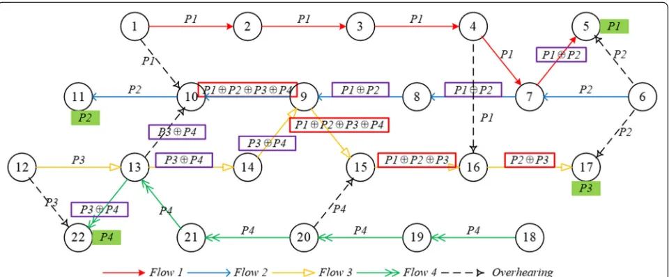
Take the scenario in Fig.6for example. There are four flows in Fig. 6 marked with different colored lines and arrows. The dashed line with arrow represents the over-hearing relationship between two nodes.
In Fig.6a, flow 1 and flow 2 can be coded at node 7, whileflow 3andflow 4can be coded at node 13, accord-ing to MCC. Since flow 2 and flow 3 are both coded flows, and for node 9 there are no upstream node to ex-tract the intended native packet for node 9, there should be no coding opportunity at node 9 according to GCC. However, it is obvious from Fig.6a thatflow 3andflow 4
can be coded at node 9 and each flow can obtain its native packet eventually.
Figure 6billustrates the false coding scenario without enough packets for decoding. In Fig.6b,flow 2and flow 3 are coded at node 9. However, since flow 3 overhears
P2 and P4 at node 17 and 15 respectively, the destin-ation node 17 can eventually obtain the coded packet
P1⊕P3, which is not intend native packet P3. The reason behind is that flow 3 does not overhear P1 for decoding, resulting in the failed decoding. Similarly, the destination of flow 2, node 11 eventually gets coded packetP2⊕P4, instead ofP2.
After modifying the relative positions of node 5, 6, 7 in Fig.6b, we get the Fig.6c. In Fig.6c,flow 3is coded with
flow 2at node 9, andflow 3overhears packetP2,P4,P1⊕ P2at node 16, 17, 17 respectively. It appears that flow 3
get enough packets for decoding on P1⊕P2⊕P3⊕P4. However, it is clear that node 16 obtains P1⊕P3⊕P4
through overheard P2 XORing with P1⊕P2⊕P3⊕P4. Then node 17 obtains P1⊕P3 through overheard P4
XORing with P1⊕P3⊕P4, or obtains P2⊕P3 through overheadP4,P1⊕P2, XORing withP1⊕P3⊕P4. In this scenario, flow 3cannot obtain native packet, although it gets enough packets for decoding according to GCC.
From the above analysis, it can be found that GCC is de-rived from Fig.5. And GCC exists coding opportunities loss and failure decoding problem in certain scenarios. There-fore, it is essential to investigate the network coding condi-tion failure problem and propose universal network coding condition through in-depth analysis of MCC, GCC.
Before presenting the EMCC, related terms are given. The packet before network coding operation is called pre-coded packet, while the result of network coding op-eration is called en-coded packet. The aim of EMCC is to assure the destination can get the pre-coded packet.
For a node c of a flow f, if node c operates network coding on packets of flow f, then the node c is called coding node of flowf. For a nodevof a flowf, if nodev
receives packet P of flow f, the node s of flow f firstly sends out the packet P, then node s is called the initial
node of node v for flow f and the initial node is repre-sented byin(v,f).
For a flowfand one node vonf, letUI(v,f) denote the set of nodes that traverses backward from nodevto the
in(v,f). Obviously, if there is no coding node in U(v,f), then UI(v,f) =U(v,f). Otherwise,UI(v,f) U(v,f), and the
UI(v,f) consists of all nodes that traverse from nodevto the first coding node.
Assume the path of flowffrom source nodeSto destin-ation node D is S→N1 →N2…Nc →Nc + 1Nc + 2…→
Nn-2→Nn-1→Nn→v→Nn + 1→Nn + 2…→Nn + m→D, andin(v,f) isNc, then there areUI(v,f)={Nc…,Nn-1,Nn}.
Take the scenario in Fig. 6a for example. Flow 2 and
flow 3 intersects at node 9. Before node 9, flow 2 has been coded at node 7 withflow 1,flow 3has been coded at node 13 withflow 4. Therefore,flow 2 andflow 3 are both coded flows. And there arein(9,flow 2) = 7,U(9,flow 2) = {8,7,6}, UI(9,flow 2) = {9,8,7}, in(9,flow 3) = 13,
U(9,flow 3) = {9,14,13,12},UI(9,flow 3) = {9,14,13}. Theorem 1Extended Multi-hop Network Coding Condi-tion(EMCC)
Assume two flows, f1 and f2, intersect at node v, and the channel condition and scheduling are ideal, then the sufficient condition for f1andf2to perform correct net-work coding and decoding is as follows:
(1)∃d1∈D(v,f1), such that d1∈N(s2), s2∈UI(v,f2), or
d1∈UI(c,f2).
(2)∃d2∈D(v,f2), such that d2∈N(s1), s1∈UI(v,f1), or
d2∈UI(c,f1).
Proof To prove the sufficiency of EMCC, the proof is divided into three circumstances.
① Circumstance1: f1 and f2 are not coded before node v.
In this case, there are UI(v,f1) =U(v,f1) and UC(v,f2) =U(v,f2), and EMCC is just the same as MCC. There-fore (1) and (2) is sufficient conditions for coding op-portunity at nodev, according to MCC.
②Circumstance2: One off1andf2is coded before nodev. Assume thatf1is coded before arrivingv, coded packet Pcfromf1arrive at nodev, while native packetP2fromf2 arrive at nodev. In this case,UI(v,f2) =U(v,f2).
It is assumed that (1) and (2) hold. According to (2),
d2 receive coded packet (Pc⊕P2), and it maintains
(d2∈UI(c,f1)) or overhears the packet Pc (d2∈N(s1)), then d2 could decode through (Pc⊕P2)⊕Pc=P2 to get P2. According to (1),d1receive coded packet (Pc⊕P2), and it maintain or overhear the packetP2, thend1could de-code through (Pc⊕P2)⊕P2=Pcto getPc. For packetPc, it will be decoded to native packet eventually through it-erative iteration according to (1) and (2). If f2 is coded before arrivingv, the proof is similar. Therefore,f1andf2 can be coded at v, and both f1 and f2 can decode cor-rectly to get pre-coded packets. Sufficiency of EMCC is proved.
③Circumstance3: Bothf1andf2are coded before nodev. It is assumed that (1) and (2) hold, and the pre-coded packets off1andf2arePc1andPc2respectively. According to (1),d1receive coded packet (Pc1⊕Pc2), and it maintains (d1∈UI(c,f2)) or overhears the packet Pc2(d1∈N(s1)), then d1could decode through (Pc1⊕Pc2)⊕Pc2=Pc1to getPc1. Similarly, d2 could decode through (Pc1⊕Pc2)⊕Pc1=
Pc2 to get Pc2. Then both f1 and f2 can decode cor-rectly to get pre-coded packets. Sufficiency of EMCC is proved.
Take the scenario in Fig.6aas an example to illustrate the principles of EMCC. In Fig.6a,flow 2andflow 3intersects at node 9. There are (1)10∈D(9,flow2), such that10∈N(14), 14∈UI(9,flow3);(2) 15∈D(9,flow3), such that 15∈N(8),
8∈UI(9,flow2). According to EMCC, flow 2andflow 3can be coded at node 9. And node 10 and 15 can get pre-coded packets respectively. And Fig.6aconfirms the judgment ac-cording to EMCC.
However, the EMCC is only sufficient network cod-ing condition, and there is doubt that whether it is necessary network coding condition. That is when f1 and f2 can code at v, whether (1) and (2) still hold. To prove the un-necessity of EMCC, a counterexam-ple is given in Fig. 7.
In Fig.7, there are four flows. According to EMCC,flow 1andflow 3can be coded at node 6, whileflow 2andflow 4 can be coded at node 9. Besides,flow 1 intersects with
flow 2 at node 12. And there are UI(12,flow 1) = {7},
UI(12,flow 2)={8},11∈N(5),13∈N(10).That is to say that condition (1) and (2) are not satisfied. According to EMCC,
flow 1andflow 2cannot be coded at node 12. Nevertheless,
flow 1andflow 2can be coded at node 12 actually, since node 11 and node 13 can get native packet successfully through decoding. Therefore, two flows satisfied with (1) and (2) of EMCC can be coded together. But two flows which can be coded together at intersecting node might not satisfy the (1) and (2) of EMCC. In other words, if two flows can be coded together, it is not necessary that (1) and (2) of EMCC hold, which is sufficient not necessary.
Analyzing the scenario in Fig. 7, it is obvious that EMCC restricts the overhearing from the node in
UI(v,f) to ensure that the overheard packets are just the packets participating network coding to guarantee the correct decoding at downstream node. However, the overhearing can be at the upstream node of the node in UI(v,f) which further extends the scope of overhearing in EMCC. This motivates us to propose universal network coding condition (UCC).
Assume one node vis the neighbor of node s, then v
can overhear packet sent bys, and the packet overheard by v from s is marked as OH(s). And s is called
over-heard node, whilevis calledoverhearing node.P
i¼1 m
OHðsiÞ
represents the XOR operations of multiple parameters,
i.e., P
i¼1 m
OHðsiÞ ¼OHðs1Þ⊕OHðs2Þ…⊕OHðsmÞ. Pc is the
XOR result ofnnative packets (p1,p2,…pn).G(Pc) is the set of native packets formingPc. Assume one nodevon flowfsends packetP. The packetPis the XOR result of
m native packets (P1, P2, …Pm). If m < n and G(P) ⊂
G(Pc), thenfis called the related flow of Pc, and nodev is called the related node of Pc. The set of related nodes of coded packetPcis marked asRN(Pc).
Theorem 2 Universal Network Coding Condition for Two Flows(UCC-2)
Assume two flows, f1and f2, whose native packets are P1and P2respectively, intersect at nodev, and the chan-nel condition and scheduling are ideal. The packets ar-rive at nodevfromf1andf2areP’1and P’2respectively, andPc=P’1⊕P’2. Then the necessary and sufficient con-dition for f1 and f2 to perform correct network coding and decoding is as follows:
(1)∃di∈D(v,f1), such thatdi∈N(s2i),
Proof The proof of UCC-2 is divided into sufficiency proof and necessity proof.
Sufficiency Proof: Assume (1) and (2) hold, andf1andf2 are coded at nodev. Then for flowf1, at each overhearing
nodedi,dican operate decoding through Pc⊕ f2can get native packet through decoding successfully, and they can be coded at nodev. The sufficiency is proved.
Necessity Proof: Assumef1andf2can be coded at node v, then f1and f2 should be able to get the native packet through decoding at the overhearing node. EMCC requires that the overheard nodes should be in UI(v,f). However, the scenario in Fig. 7 illustrates that the overheard node can be extended toU(v,f). Assume there aremoverhearing nodes on f1. For overhearing node di∈f1, it can get over-heard packetOH(s1i) from overheard nodes1i onf2. Since f1 can get the native packet P1, the coded packet Pc is decoded at eachdilike peeling onion, and at nodedm, the
native packetP1is obtained throughPc⊕
P
i¼1 m
OHðs2iÞ ¼P1.
Therefore, (1) holds. Similarly, the (2) holds. The necessity is proved.
Based on the above proof of sufficiency and necessity, the UCC-2 is proved.
Take the scenario in Figs. 7 and 8 as examples to illustrate the principle of UCC-2. In Fig.7,flow 1andflow 2
intersect at node 12. Forflow 1andflow 2,Pc=P1⊕P2. (1) 13∈D(12,flow 1), 13∈N(10), 10∈U(12,flow 2), OH(10)=P2
and there are Pc⊕P2=P1. (2)11∈D(12,flow 2), 11∈N(5), 5∈U(12,flow 1), OH(5)=P1 and there are Pc⊕P1=P2. Therefore,flow 1andflow 2in Fig.7can be coded at node 12 according to UCC, and Fig.7confirms the judgment.
The scenario in Fig.8is similar with that in Fig.6b, and
flow 2 and flow 3 intersect at node 9, where Pc=P1⊕ OH(4)⊕OH(6) = P3. Therefore, according to UCC-2,flow 2andflow 3can be coded at node 9 and each flow can get native packet respectively.
AssumeNflows,f1,f2,…,fN, intersect at nodev, and the channel condition and scheduling are ideal. Then the ne-cessary and sufficient condition for theNflows to perform correct network coding and decoding is that for any two flows of theNflows,fiandfj(i≠j), satisfy UCC-2.
Proof The proof of UCC-N is divided into sufficiency proof and necessity proof.
(1) Sufficiency Proof: Assume any two flows of theN flows,fiandfj, satisfy UCC-2, and their native packets arePiandPjrespectively, and the packets arriving at nodevarePi’andPj’respectively. Ac-cording to UCC-2, flowfican get its native packet PithroughP’i⊕P’j⊕
P
k¼1 mj
OHðsjkÞ. Assume the
packets of theNflows coded atvand form the coded packetPc=P’1⊕P’2⊕…⊕P’N. Assumei= 1,
Accordingly, whenN= 2, there are
Pc¼P’1⊕P’2¼P1⊕
According to above rules, whenN=2 k, there are
Pc¼P1⊕
Therefore,flow 1can get the native packetP1 eventu-ally according to formula (1) and (2). In other words, each flow can get the native packet since the flow 1 is random chosen from N flows, and the N flows can be coded at nodevand each flow can decode successfully.
(2) Necessity Proof: Assume theNflows can be coded at nodev, then each flow can get their native packets respectively through decoding. For any two flows of theNflows,fiandfj, (i! = j), there are:
Pc⊕K¼Pi; ð3Þ
Pc⊕M¼Pj; ð4Þ
where Pc=P’1⊕P’2…⊕P’i…⊕P’j…⊕P’N, K is the XOR result of overheard packets by fi, M is the XOR result of overheard packets byfj.
The coded packetPccan be expressed with two parts as
Pc¼P’i⊕P’j⊕P’1…⊕P’i−1⊕P’iþ1…⊕P’j−1⊕P’jþ1…⊕P’N
¼P’i⊕P’j⊕Puij;
wherePuijis the XOR result of arriving packets of the flows except fi and fj, Puij=P’1…⊕P’i-1⊕P’i + 1…⊕P’j-1⊕P’j +
1…⊕P’N.
In addition, the K and M can also be expressed with two parts as
K¼Kj⊕Kuij;
whereKjis the XOR result of overheard packets related to fj, while Kuij is the XOR result of overheard packets unrelated tofiandfj.
Similarly,
M¼Mi⊕Muij;
whereMiis the XOR result of overheard packets related to fi, while Muij is the XOR result of overheard packets unrelated tofiandfj.
Then formula (3) and (4) can be further expressed as
P’i⊕P’j⊕Puij⊕Kj⊕Kuij¼P’i⊕P’j⊕Kj⊕ Puij⊕Kuij
Since Puij contains information of the flows except fi and fj, and fi need to get native packet Pi, the result of
Puij⊕Kuijshould be all zero. Similarly,Puij⊕Muijshould also be all zero. According to the rule of XOR, formula (5) and (6) can be reduced as
According to formula (9) and (10), fiandfj satisfy the UCC-2.
Based on the above proof, the sufficiency and necessity of UCC-N are proved.
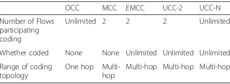
The comparison of the typical network coding condi-tions with UCC is presented in Table1.
In addition, decoding as soon as possible (ASAP Decod-ing) is the principle of NAER. The overhearing may hap-pen at several nodes after the coding node. ASAP decoding means that the decoding should take place at the first overhearing node to ensure the coded packets is decoded as soon as possible after coding. Take the sce-nario in Fig. 9 as an example. The scenario in Fig. 9 is
Table 1Comparison of typical network coding conditions with UCC
OCC MCC EMCC UCC-2 UCC-N
Number of Flows participating coding
Unlimited 2 2 2 Unlimited
Whether coded None None Unlimited Unlimited Unlimited
Range of coding topology
One hop Multi-hop
similar with that of Fig. 7a. flow 1 and flow 2 codes at node 7, while flow 3 and flow 4 codes at node 13. However, flow 2 decodes at node 8, and flow 3 de-codes at node 14. When the flow 2 and flow 3 reach node 9, both of them send native packet. Then Fig. 9 is clearer than that in Fig. 7a.
4.2 Principle of cross layer network coding aware
Figure5illustrates the improvements to MCC by GCC. To achieve the network coding opportunity at node 5, GCC in-serts node C into the network as Fig.5b,cor enhance the transmission range of node 2 as Fig.5d. However, adding new node into network is impossible for ordinary fixed net-work. On the other side, topology control and coverage control, which control the transmission range or node’s mode (sleeping or working) in network, is ordinary in wireless sensor network due to the energy efficiency de-mand. In addition, cross layer mechanism has become a promising technology to improving the overall net-work performance. Therefore, NAER attempts to ex-ploit cross layer mechanism to increase network coding opportunities through combining network coding op-portunities discovery mechanism with topology control and coverage control.
Topology control and coverage control algorithms affect the discovery of some potential network coding opportun-ities. Taking the scenario in Fig.6bas an example, theflow 2andflow 3cannot code at node 9 in Fig.6b, since both flows cannot get native packets respectively. Nevertheless, if enhance the transmission range of node 4 and 21 through updating the topology control, and let node 16 and 10 overhear the packet from 4 and 21 respectively as shown in Fig.10a, then node 11 and node 17 can get the native packetP2andP3correctly.
On the other hand, if wake the sleep nodes, node N1 between 9 and 10, node N2 between 15 and 16, through updating the coverage control mechanism, then flow 2 and flow 3 can get native packets through decoding successfully as well as shown in Fig. 10b.
Therefore, it is clear from Fig.10that network coding opportunities can be further increased through combing network coding opportunity discovery with topology control and coverage control, which motivate NAER to present the idea of cross layer network coding opportun-ity aware mechanism. Figure11depicts the principles of cross layer interactions in NAER.
4.3 Network coding aware energy efficient routing metric
Although increasing the number of coding opportunities is one goal of network coding aware routing, the route with most coding opportunities in WSNs may not be opti-mal in energy consumption, quality of each link, or other aspects. Therefore, it is necessary to design a comprehen-sive routing metric that takes into account factors such as node energy, network coding opportunities, and wireless link quality. In this paper, the network coding aware en-ergy efficient routing metric (NERM) is proposed.
Since energy efficiency is a fundamental demand of protocol design for WSNS, NERM is designed from the prospective of energy consumption. Assume lij is the link from node ito nodejon route R. Then the NERM value oflij,NERM(lij)is defined as follow.
NERM lij ¼ ðSECð Þ þi RECð Þj Þ EFð Þi ð11Þ
where SEC(i) is the sending energy consumption at nodei, REC(j) is the receiving energy consumption at nodej, and EF(i) is the energy factor of node i and will be explained below.
Fig. 10Example to illustrate the benefit of cross layer network coding aware. Figure 10 illustrates two example scenarios to show the coding opportunities creating through combining routing with topology control and coverage control.aCorrect decoding using UCC after topology control updating.bCorrect decoding using UCC after convergence control updating
Assume the route R can be coded with other flows at nodei, and the number of flows participating coding isc(i), then thec(i) native packets of thec(i) flows can be coded and sent out in one coded packet. Therefore, the energy consumption forRatiis1/c(i) of the energy consumption for coded packet transmission. Whenc(i) is 1, it means that there exists no coding opportunity at nodeiforR.
Sincelijis wireless channel, sending and receiving on it follows probability model. In other words, the sending and receiving on lij may not succeed in one time. Therefore, the expected transmission numberE(lij)is used to reflect the link quality oflij. Letφ(lij)represent the needed trans-mission count for one successful transtrans-mission onlij, then
E(lij)is calculated as follow.
E lij ¼
LetET(i) denote the energy consumption intensity for sending at nodei.ET(i) is expressed as follow.
ET ið Þ ¼ETElecþεampdγ ð13Þ
whereETElecis the energy consumption for sending of unit data,εampis the energy consumption of amplifier for sending
of unit data,dis the distance between sender and receiver, andγis the path loss coefficient whose value is in [2,4].
Then SEC(i) can be calculated as follow.
SECð Þ ¼i E lij
1
c ið Þ ETð Þi ð14Þ
AssumeERElec(j) is the energy consumption for receiv-ing of unit data, thenREC(i)can be expressed as follow.
RECð Þ ¼i E lij ERElec ð15Þ
In wireless sensor network, once one node’s energy is exhausted, the node will no longer send or receive, result-ing in routes interruption. Therefore, NERM should con-sider the energy of nodes on routes to avoid selecting nodes with less energy and balance the energy consump-tion in the network. The energy factor of nodei,EF(i)is to reflect the node’s energy. AssumeEL(i) is the percentage of node’s remaining energy,EL(i)is calculated as follow.
EL ið Þ ¼Erð Þi
Etð Þi ð
16Þ
whereEr(i)is the remaining energy of nodei, andEt(i)is the initial total energy of nodei.
ThenEF(i)is expressed as follow.
EF ið Þ ¼e−EL ið Þ ð17Þ
Based on the calculation of NERM value of linklij, the NERM value of the routeRis expressed as follow.
NERM Rð Þ ¼X
R
lij∈R
NERM lij ð18Þ
It is clear from the formula (18) that a larger number of participating coding flows better link quality, and a larger percentage of remaining energy lead to a smaller NERM value of RouteR, which implies that lower level of energy consumption of routing and better routing performance. Compared with the routing metric of other network coding aware routing, NERM has the following features: (a) NERM jointly considers coding opportunity, link quality, and node energy, instead of only pursuing the increment of coding opportunities. (b) The NERM calculation is based on the energy consumption which is critical for energy constraint wireless sensor network. (c) The NERM value of routes can be calculated in distrib-uted manner after the route discovery phase, and source node select the routes according to their NERM value.
4.4 NAER procedure
The procedure and implementation details of NAER are presented in this section.
In NAER, each node maintains following elements:
(a) Neighbor table (NT): NT is used to record information of neighbors, which include IDs and state ofActiveneighbors, temporaryUnreachable neighbors due to topology control, andSleeping neighbors due to coverage control.
(b) Cycle buffer queue (CBQ): CBQ is set to store the overheard packets from neighbors.
(c) Flow table (FT): FT records the detailed
information of the flows traversing through current node, including the flow ID, the ID of each node on these flows, and the neighbors’information of each node on these flows.
(d) Overhearing state (OHS): OHS is a Boolean type value, with HEAR meaning that the node can overhear and cache packets from neighbors, and UNHEAR meaning that the node will drop packets not for itself from neighbors. At the initial stage of the network, all nodes are set to the UNHEAR state.
(e) Routing table (RT): Routing table includes the source routings from current node to other nodes in the network.
topology control. Therefore, the neighbors’state should be updated after coverage control and topology control. In other coding aware routing, the coding opportun-ities are usually calculated at intermediate node in route reply phase, i.e., along the reverse path discovered by routing request phase. However, NAER allows the mul-tiple coding nodes on one path. If the coding opportun-ity is calculated as the other coding aware routing, the already calculated coding opportunities at downstream nodes may be turned to be false-coding node when cal-culate the coding opportunities at upstream nodes. Therefore, the coding opportunities calculation of NAER should be along the path discovered by route request phase, instead of reverse order.
Then there is doubt that whether the coding opportun-ity can be calculated at source nodeS. However, according to UCC-2 and UCC-N, to calculate the coding opportun-ity at one node, it is essential for current node to know the information of flows traversing the current node and neighbors’information of each node on these flows. If the coding opportunity is calculated at source nodeS, all the above information needs to be collected to send to S, which is too large and will consume lots of energy.
Therefore, two additional phases called coding opportun-ity calculation phase and coding reply phase are introduced in NAER, to calculate coding opportunities in distributed manner to avoid the related information transmission. And totally, NAER needs three round-trip interactions between source and destination to complete the routing discovery procedure: one round-trip interactions to discover routes, one round-trip interactions to calculate coding opportun-ities, and one round-trip interactions to specify the overhearing node.
When a new arriving flow whose source is nodeSand destination is node D is injected into the network and there is no route entry for the flow in RT of node S, S
starts routing discovery procedure. The routing discovery procedure of NAER includes six phases: (1) Route request, (2) Route reply, (3) Coding opportunity calculation,
(4) Coding reply, (5) Routing and coding confirm, and (6) Routing and coding reply.
The detailed steps of NAER are described as follows.
(1) Route request
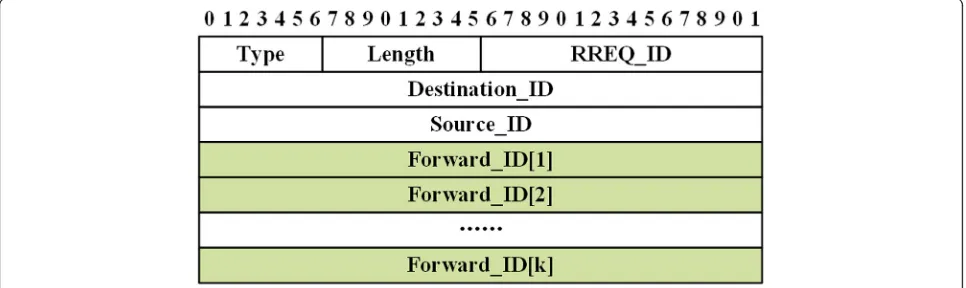
Sgenerates route request (RREQ) message and broad-casts it to its neighbors. The structure of RREQ in NAER is shown in Fig.12. The field“Type”indicates the type of the message. The length of the RREQ is given in field “Length.” The field “RREQ_ID” is the consequence ID of the RREQ message. “Source_ID” and “ Destinatio-n_ID”are the IDs of the source and destination respect-ively. The ID of each node that RREQ traverses is recorded in the field“Forward_ID”.
Upon receiving an RREQ, the intermediate node v
proceeds as follows.
① If node v have received one RREQ message with the same RREQ_ID, node v drops the latest received RREQ.
②Add the ID of nodevinto RREQ.
③Rebroadcast the updated RREQ message to discover the remaining path.
(2) Route reply
When RREQ arrives atD,Dproceeds as follows. ① Copy the IDs of the node on the path collected by RREQ to create corresponding RREP message, whose structure is shown in Fig.13.
② Unicast the RREP to nodeSalong the reverse path discovered by RREQ.
As shown in Fig. 13, the field“RREP_ID”is the conse-quence ID of the RREP message. The“Neighbors_ Infor-mation” field stores the number of current node’s neighbors and ID of each neighbor. The rest field of RREQ is the same as that of RREQ.
(3) Coding opportunity calculation
Upon receiving RREQ message, nodeS set a timerTs, and create route coding opportunity calculation (RCOC) message for each RREQ arrived within Ts. The structure of RCOC is shown in Fig.14. ThenSunicast the RCOC to nodeDalong the path discovered by RREQ.
As depicted in Fig. 14, the field “RCOC” is the consequence ID of RCOC. “Energy_Percent”implies the remaining energy percentage of current node.“ Link_Qu-ality”indicates the successful transmission probability of the link form current node to next hop, while“ Link_Dis-tance” is the distance between current node and next hop. In addition, “Code_State” field is bool type value,
which indicates whether the path can be coded with existing flows at current node. If “Code_State” is set true,“Num_Code”will give how many flows will partici-pate in the network coding, “Code_Flow_Information” will present the IDs of flows involving network coding, and “Overhear_Information” will give the IDs of nodes involving the overhearing.
Upon receiving RCOC message, intermediate node v
proceeds as follows.
①Collect v’s remaining energy percentage, the quality and the distance of the link fromvto next hop, and up-date related fields in RCOC.
Fig. 13Structure of RREP Message. Figure 13 shows the structure of RREP message, including the name of fields and their length
②Ifv’s FT is not empty, execute the network coding op-portunity calculation algorithm as shown in Algorithm 1 based on the Neighbors_Information in RCOC andv’s FT.
③ If there exits coding opportunity atvfor the path dis-covered by RREQ, set the“Code_State”field as TRUE, and update “Number_Code,” “Code_flows_Information,” “ Over-hear_Information”fields based on the results of Algorithm 1.
(4) Coding reply
When D receives RCOC, it proceeds as follows. ① Based on the information in RCOC, it create route and coding opportunity reply (RCOR) message. The struc-ture of RCOR is as shown in Fig.15. It is obvious that the structure of RCOR is almost the same as that of RCOC other than the field “Neighbors_Information,” which is not essential for calculation of NERM value.
② Unicast RCOR message along the reverse path dis-covered by RREQ.
③Intermediate node just forwards RCOR without any modifications.
(5) Routing and coding confirm
WhenSreceives RCOR, it proceeds as follows. ①Calculate the NERM value of the path stored in RCOR. ② Select the path with the minimum NERM value as final routing and updateRT.
③ S creates routing and coding confirm (RCON) mes-sage and unicast it to nodeD. The structure of RCON is shown in Fig.16. Compared with RCOR, the structure of RCON deletes the fields related to NERM calculation, e.g., “Energy_Percent,” “Link_Quality,”and“Link_Distance.”
When an intermediate node vreceives RCON, it pro-ceeds as follows.
①Update its FT according to the path of RCON. ② Set the working mode of the node in SO_ID to overhear packets from the node in RO_ID.
③If the TS is not NULL, execute the topology control mechanism to require the nodes in TS to enhance trans-mission range. If the CS is NULL, execute the coverage control mechanism to wake up the nodes inCS.
(6) Routing and coding reply
WhenDreceive RCON, it proceeds as follows.
Create route and coding acknowledgement (RACK), and unicast it toS. The structure of RACK is shown in Fig.17. The structure of RACK is similar with that of RREQ, and deletes unnecessary fields to reduce the data to transmit.
② When S receive the RACK, it begins to transmit data using the routing in RT.
5 Simulations and performance analysis
5.1 Parameters for simulations
In order to evaluate the performance of the proposed NAER, extensive simulations are conducted using NS2 platform. In addition, COPE [16], DCAR [18], and FORM [19] are also simulated as comparison items. As the simulations of typical network coding aware routings, e.g., DCAR [18], FORM [19], and so on, grid topology and random topology are considered in simulations. Besides, to investigate the contribution of cross layer network coding aware, with and without topology and coverage
control cases are considered respectively. Therefore, the simulation scenarios are listed as follows to analyze the performance of NAER.
(1) Scenario 1: 100 nodes form a 10 × 10 grid network which is uniformly deployed in a square area of 500 m × 500 m. In this case, there is no topology control or coverage control, and all nodes are active.
(2) Scenario 2: 150 nodes are uniformly deployed in a square area of 500 m × 500 m. Universal network Fig. 15Structure of RCOR Message. Figure 15 shows the structure of RCOR message, including the name of fields and their length
coding condition and cross layer network coding aware are focus of this paper, instead of topology control algorithm and coverage control algorithm. Therefore, topology control exploits the classical node scheduling scheme (NSS) [30] algorithm, and coverage control uses traditional local mean algorithm (LMA) [31], to illustrate the benefit of cross layer network coding aware.
The MAC layer of the node adopts IEEE 802.15.4, whose channel capacity is 250Kbps and sending queue size is 100. Besides, the packet size is 128 byte. The data flow in the network is set to constant bit rate (CBR) type and the data flow rate is 8 kbps. The source and destin-ation of each CBR flow are randomly selected from ac-tive network nodes. The other detailed simulation parameters are shown in Table2. In the simulations, the
number of flows is increased gradually to analyze the performance of routings under different network load.
5.2 Simulation results analysis 5.2.1 Scenario 1: grid network
Figure 19 presents the network throughput using four routings under different number of flows in grid net-work. It is clear that as the number of flows grows, the network throughput increases, but the advantage of NAER becomes obvious. The network throughput of NAER exceeds that of COPE 9.85%, DCAR 6.62%, and FORM 3.57% with 20 flows. When the number of flows is increased to 40, the gaps of the network throughput turn into 29.07%, 15.63% and 6.73%, individually.
The reason is that the network coding opportunity is rare, which leads to comparable network throughput of four routings, when the number of flows is small. How-ever, the chances of cross-over and overlapping among flows increases with the ascending of flows number which creates more coding opportunities among routes. As net-work coding aware routing, DCAR, FORM, and NAER can discover and exploit coding opportunities to save bandwidth and reduce interference, which improve net-work throughput eventually. Sine COPE can only discover coding opportunities in established routes, which neglects many potential coding opportunities, the network throughput of COPE is the lowest in the four routings. Furthermore, compared to DCAR and FORM, NAER has a better throughput because it improves the network cod-ing condition of DCAR and FORM, and proposes UCC which increase the quantity of coding opportunities and guarantee the decodable of coded packets.
The average end-to-end delay under different number of flows is given in Fig. 20. It is clear that the average end-to-end delay of the four routings rises, as the number of flows ascends. Due to the extra coding opportunity dis-covery process in routing disdis-covery, DCAR, FORM, and NAER have larger average end-to-end delay than COPE, when the number of flows is less than 28. In addition, when the number of flows is over 30, the average end-to-end
Fig. 17Structure of RACK Message. Figure 17 shows the structure of RACK message, including the name of fields and their length
Table 2Simulation parameters setting
Parameters Value
MAC layer protocol IEEE 802.15.4
Transport layer protocol UDP
Application layer traffic CBR
Signal transmission range 50 m
Signal interference range 100 m
Channel capacity 250 kbit/s
Output queue type FIFO
Cache capacity 50 Packets
Packet size 128 Byte
Initial energy 100 J
ETElec(normal, max) 50 nJ/bit, 100nJ/bit
ERElec 50 nJ/bit
εamp 10 pJ/bit/m
2
γ 2
Simulation area 500 m × 500 m
delay of the four routings grows greatly. The reason behind the phenomenon is that congestion is more likely to hap-pen in network as the number of flows is over 30. However, since NAER discovers more coding opportunities which save node bandwidth, it has the least delay compared with other three routings when the number of flows is over 32.
The energy consumption per packet is the ratio of nodes’ total energy consumption to the number of all transmitted packets. The energy consumption per packet comparison of four routings with different number of flows is exhibited in Fig. 21. It is clear that NAER has a slight advantage when the number of flows is small. When the number of flows grows, NAER has a larger superiority compared to the other three routings. There are two reasons for this phenomenon. On the one hand, NAER presents UCC and exploits more coding oppor-tunities among routings which reduce the number of transmissions and reduce the energy consumption per packet actually. On the other hand, NAER can guarantee the decodable of coded packets to avoid retransmission compared with other three routings.
The network lifetime in NAER is defined as the time until the first sensor node run out of energy and die. Figure 22 exhibits the network lifetime under different number of flows in grid network. It can be found from Fig. 22that the network lifetime of the four routings is close when the number of flows is less than 12. The gap
among the four routings becomes larger as the number of flows increases. Moreover, the network lifetime of the NAER is always longer than COPE, DCAR, and FORM, especially with larger number of flows, indicating that NAER achieves a better energy consumption perform-ance. The reason is that NAER presents the routing metric NERM which considers the node’s energy and balance network energy consumption. In addition, NAER can discover more coding opportunities through using UCC, which reduce number of transmission and save node’s energy consumption.
The coded packet percentage is calculated as the num-ber of coded packets to the total numnum-ber of packets trans-mitted in network, which reflects the approximate quantity of the coded packets in the network transmission. The coded packet percentage under different number of flows in grid network is shown in Fig. 23. It is obvious from Fig.23that the coded packet percentage of the four routings is comparable due to fewer coding opportunities when the number of flows is less than 6. The coded packet percentage of the four routings ascends gradually with the number of flows increasing. And the coded packet per-centage of COPE is far less than DCAR, FORM, and NAER when the number of flows is over 8, since it dis-covers less coding opportunities compared with other routings. And the gap among DCAR, FORM, and NAER becomes larger when the number of flows is over 16. The
reason behind the phenomenon is that NAER presents UCC improved from DCAR and FORM and can discover more potential coding opportunities.
Since NAER can discover more coding opportunities through UCC, it is essential to analyze the coding tunities in NAER through classifying the coding oppor-tunities based on the coding conditions. In fact, all the coding opportunities in NAER are discovered based on UCC. The classification of coding opportunities means to confirm whether one coding opportunity in NAER
can be discovered using MCC, EMCC, UCC-2, or UCC-N. The purpose of the classification is to analyze the contribution of UCC-2 and UCC-N to coding oppor-tunities discovery. The coding condition percentage of NAER under different number of flows in grid network is shown in Fig.24.
It is interesting from Fig.24that different coding con-ditions have different trend as the number of flows in-creases. When there are two flows, the MCC is 100%. However, MCC decreases sharply with the increasing of
Fig. 20Average end-to-end delay under different number of flows in grid network. Figure 20 shows the average end-to-end comparison of COPE, DCAR, FORM, and NAER under different number of flows in grid network
number of flows, because MCC requires that the two intersecting flows should not be coded before the inter-secting node, which is hard to be satisfied in network with more flows. EMCC increases first and then de-crease when the number of flows is 8, since EMCC has no limitation on whether the flows have been coded be-fore intersecting node, but strictly limits the node of overhearing, thus reduces the coding opportunities as
the number of flows increases. UCC-2 increases rapidly when the number of flows is between 6 and 16. When the number of flows is over 16, UCC-2 is over 40% and grows slower, but far larger than other coding conditions since UCC-2 can find many potential coding opportun-ities that MCC and EMCC cannot discover. UCC-N dis-covers the coding opportunities involve multiple flows which is usually greater than 3. As the number of flows
Fig. 22Network lifetime under different number of flows in grid network. Figure 22 shows the network lifetime comparison of COPE, DCAR, FORM, and NAER under different number of flows in grid network
grows, the chance that multiple flows intersect at one node increases and the coding condition percentage of UCC-N ascends gradually.
5.2.2 Scenario 2: random network
Figure 25presents the network throughput under differ-ent number of flows in random network. It can be seen from Fig.25that the changing trends of network through-put for all the four routings in the random network are similar to those in the grid network. The network throughput of network coding aware routing DCAR, FORM, and NAER outperforms that of COPE under dif-ferent number of flows. At the same time, NAER has the best throughput and its advantage over FORM is more obvious than that in grid network shown in Fig. 19. The reason is that NAER can discover more coding opportun-ities through cross layer interaction with topology control and coverage control, which further save node’s band-width and improve network throughput especially when the number of flows becomes larger.
Figure 26 depicts the average end-to-end delay under different number of flows in random network. It can be observed from Fig. 26 that DCAR, FORM, and NAER have larger end-to-end delay than COPE when number of flows is below 32 dues to the additional coding/decoding operations essential for network coding aware routing. When the number of flows is over 34, the average end-to-end delay of the four routings increases sharply. However, NAER has the slowest growth compare with other routings, since it can find more coding opportunities and save node bandwidth to postpone the network
congestion. Besides, the gap between NAER and FORM is larger than that in Fig.20when the number of flows is be-tween 34 and 40, because NARE in random network can exploit cross layer technique to exploit more coding op-portunities which further improve the average end-to-end delay performance of NAER.
Figure 27 demonstrates the energy consumption per packet under different number of flows in random net-work. It can be found from Fig.27that the trend of the changing trend of the four routings is similar with that in grid network shown in Fig. 21. When the number of flows is 2, the energy consumption per packet of the four routings is comparable. And the energy consumption per packet of the four routings decrease first and then increase when the number of flows is over 26. NAER always has the lowest energy consumption per packet when the number of flows is over 2, since NAER can discover maximum of cod-ing opportunities which reduce the number of transmission and reduce the energy consumption per packet finally.
Figure 28 shows the network lifetime under different number of flows in random network. As shown in Fig. 28, the trend of network lifetime of the four routings is similar with that in grid network drawn in Fig. 22. The network lifetime of the four routings decrease gradually with the number of flows increasing. When the number of flows is over 16, the advantage of NAER over other three routings is more obvious, and even larger than that in grid network shown in Fig. 22. Besides the analyzed reason for Fig. 22, the additional reason is that NAER in random network can detect more coding opportunities through interactions with topology
control and coverage control compared NAER in grid network.
Figure29shows the coded packet percentage under dif-ferent number of flows in random network. It is clear form Fig.29that the coded packet percentage of the four routings increases with the number of flows increasing. And NAER has a larger superiority compared to the other three routings when the number of flows grows. Besides, the value of NAER in Fig.29is higher than that in Fig.23 when the number of flows is the same. The curve of
NAER indicates that NAER can exploit most coding op-portunities since it detects coding opportunity based on UCC and interacts with topology control and coverage control to increase coding opportunities, which is consist-ent with the analysis for previous figures.
Figure 30 presents the coding condition percentage of NAER under different number of flows in random network. It can be found that the trend of the four coding conditions is similar with that in grid network shown in Fig. 24. And when the number of flows is
Fig. 25Network throughput under different number of flows in random network. Figure 25 shows the network throughput comparison of COPE, DCAR, FORM, and NAER under different number of flows in random network
over 12, coded packets based on UCC-2 and UCC-N accounts for the majority of the coded packets, which reflects the contribution of UCC-2 and UCC-N to in-crease coding opportunities.
Since the cross layer interactions (CLI) between differ-ent layers are exploited in simulations of random net-work, it is essential to investigate the contributions of the cross layer interactions with coverage control and topology control. To solve this problem, the coding
opportunities are classified into four categories: (1) No cross layer interaction is involved in the coding oppor-tunity, marked asNo CLI; (2) interactions with coverage control are involved in the coding opportunity, marked as With CC; (3) interactions with topology control are involved in the coding opportunity, marked asWith TC; and (4) interactions with coverage control and topology control are both involved in the coding opportunity, marked asWith TC & CC.
Fig. 27Energy consumption per packet under different number of flows in random network. Figure 27 shows the energy consumption per packet comparison of COPE, DCAR, FORM, and NAER under different number of flows in random network
The cross layer interaction type percentage of NAER under different number of flows in random network is presented in Fig.31. It is clear from Fig. 31that No CLI
accounts for majority (almost 100%) of the coding op-portunities when the number of flows is below 8. And
No CLI decreases gradually, while other types ascend gradually, as the number of flows increases. It is obvi-ous that No CLI always has the highest percentage
value in the coding opportunities. It is also clear that
With CC increases much faster than With TC, With TC & CC, which indicates that interactions with coverage control brings more coding opportunities than that with topology control. The reason behind the phenomenon is that topology control usually needs to increase the transmitting power of node to increase coding opportunities, which lead to the
Fig. 29Coded packet percentage under different number of flows in random network. Figure 29 shows the coded packet percentage comparison of COPE, DCAR, FORM, and NAER under different number of flows in random network
increasing of node’s energy consumption and increase the NERM value of the path. Coverage control only control the node’s working mode, and do not increase transmitting power, which will not lead to the increasing of path’s NERM value.
6 Discussion
The simulation results provide valuable insights in exploiting NAER in wireless sensor networks, which gives another way to improve energy efficiency of wire-less sensor network. Based on the simulation results analysis, the characteristics of NAER can be summarized as follows: (1) NAER increases the network coding oppor-tunities significantly since NAER exploits UCC to detect net-work coding opportunities. (2) The contribution of coverage control outperforms that of topology control in increasing network coding opportunities, because nodes’ transmitting power need to be increased to create coding opportunities through interacting with the topology control, which contra-dicts with the original intention of energy saving. (3) Al-though NAER improves the energy efficiency of WSNs, the extra coding operations and related procession increase the average end-to-end delay. Therefore, delay optimization will be an issue to addressed for NAER in future.
7 Conclusion
Due to the problem of network coding condition failure and neglection of node energy, existing network coding aware routings are not suitable for wireless sensor networks. To ad-dress these problems, a network coding aware energy effi-cient routing (NAER) for wireless sensor networks is
proposed. Based on the in-depth analysis of existing network coding condition, universal network coding condition, UCC is presented to avoid network coding condition failure prob-lem. Based on UCC, the cross layer network coding discov-ery mechanism combined with coverage control and topology control is presented to further increase the number of network coding opportunities. Simulation results on NS2 confirm that NAER can increase the number of coding op-portunities and extend the network lifetime of wireless sen-sor network. Future research work includes the delay optimization of network coding aware routing, and the load balancing algorithm for network coding aware routing.
Abbreviations
AONC:Adaptive opportunistic coding routing; CBQ: Cycle buffer queue; CBR: Constant bit rate; COPE: Coding opportunity architecture;
DCAR: Distributed coding aware routing; EMCC: Extended multi-hop network coding condition; FORM: Free-ride-oriented routing metric; FT: Flow table; GCC: General network coding condition; ID: Identification; IGCC: Improved general network coding condition; LMA: Local mean algorithm; MCC: Multi-hop network coding condition; NAER: Network coding aware energy efficient routing; NERM: Network coding aware energy efficient routing metric; NSS: Node scheduling scheme; NT: Neighbor table; OCC: One hop network coding condition; OHS: Overhearing state; RACK: Route and coding acknowledgement; RCOC: Route coding opportunity calculation;
RCON: Routing and coding confirm; RCOR: Route and coding opportunity reply; ROCX: Routing with opportunistically coded exchanges; RREP: Route reply; RREQ: Route request; UCC: Universal network coding condition; UCC-2: Universal network coding condition for two flows; UCC-N: Universal network coding condition for N flows; WSNs: Wireless sensor networks; XOR: Exclusive or
Acknowledgements
The authors would like to thank anonymous reviewers for their valuable and insightful comments and suggestions for the improvement of this paper. This work was supported in part by the National Natural Science Foundation of China (No.61502411), Natural Science Foundation of Jiangsu Province