International Journal of Research
Available at
https://edupediapublications.org/journals
e-ISSN: 2348-6848
p-ISSN: 2348-795X
Volume 05 Issue 12
April 2018
Available online:
https://edupediapublications.org/journals/index.php/IJR/
P a g e
| 4340
Abstract— The beams area unit reinforced with
outwardly warranted optical fiber bolstered compound
(GFRP) sheets. Totally different theme of strengthening
is utilized. The program consists of fourteen continuous
(two-span) beams with overall dimensions up to
(152×305×2300) metric linear unit. The beams area unit
classified into 2 series labeled S1 and S2 and every
series have totally different proportion of steel
reinforcement. One beam from every series (S1 and S2)
wasn't reinforced and was thought of as an impression
beam, whereas all alternative beams from each the series
were reinforced in varied patterns with outwardly
warranted GFRP sheets. This study examines the
responses of RC continuous beams, in terms of failure
modes, sweetening of load capability and cargo
deflection analysis. The results indicate that the flexural
strength of RC beams may be considerably hyperbolic
by gluing GFRP sheets to the strain face. Additionally,
the epoxy warranted sheets improved the cracking
behavior of the beams by delaying the formation of
visible cracks and reducing crack widths at higher load
levels.
Index Terms—GFRP, high strength, low weight, corrosion
resistance, high fatigue resistance, simple and fast installation.
INTRODUCTION
The most fashionable techniques for strengthening of RC
beams have concerned the utilization of external
epoxy-bonded steel plates. it's been found through an experiment that
flexural strength of a support will increase by victimization
this system. Though steel bonding technique is easy, efficient
and economical, it suffers from a heavy downside of
degradation of bond at the steel and concrete interphone as a
result of corrosion of steel. Different common strengthening
technique involves construction of steel jackets that is sort of
effective from strength, stiffness and malleability concerns.
However, it will increase overall cross-sectional dimensions,
resulting in increase in self-weight of structures and is labor
intensive. To eliminate these issues, plate was replaced by
corrosion resistant and lightweight FRP Composite plates.
FRPCs facilitate to extend strength and malleability while not
excessive increase in stiffness. Further, such material might be
designed to fulfill specific demand by adjusting placement of
fibers. Therefore concrete members will currently be simply
and effectively strong victimization outwardly secure FRP
composites.
By wrapping FRP sheets, retrofitting of concrete structures
provide a more economical and technically superior
alternative to the traditional techniques in many situations
because it offers high strength, low weight, corrosion
resistance, high fatigue resistance, easy and rapid installation
and minimal change in structural geometry. FRP systems can
also be used in areas with limited access where traditional
techniques would be impractical. However, due to lack of the
proper knowledge on structural behavior of concrete
structures, the use of these materials for retrofitting the
existing concrete structures cannot reach up to the expectation.
Successful retrofitting of concrete structures with FRP needs a
thorough knowledge on the subject and available user-friendly
technologies/ unique guidelines.
EXPERIMENTAL STUDY
The experimental study consists of casting of fourteen large
scale continuous (two-span) rectangular reinforced concrete
beams. All the beams weak in flexure are casted and tested to
failure. The beams were grouped into two series labeled S1
and S2. Each series had different longitudinal and transverse
steel reinforcement ratios which are mentioned in Table 3.5
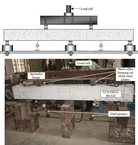
and Table 3.6 for S1 and S2 respectively. Beams geometry as
well as the loading and support arrangements are illustrated in
Figure 3.6. All beams had the same geometrical dimensions:
152 mm wide × 305 mm deep × 2300 mm long.
One beam from each series (S1 and S2) was not strengthened
and was considered as a control beam, whereas all other
beams from both the series were strengthened with externally
bonded GFRP sheets. Experimental data on load, deflection
and failure modes of each of the beams are obtained. The
change in load carrying capacity and failure mode of the
Study of Strengthening Rc Continuous Beam Using Fiber
Reinforced Polymer Under Static Loading
Ch. Amarnadh
1, V. Kanaka Durga
21
M.Tech Student,
2Asst.Professor
M.Tech Structural Engineering,
International Journal of Research
Available at
https://edupediapublications.org/journals
e-ISSN: 2348-6848
p-ISSN: 2348-795X
Volume 05 Issue 12
April 2018
Available online:
https://edupediapublications.org/journals/index.php/IJR/
P a g e
| 4341
beams are investigated for different types of strengthening
pattern.
Detailing of Reinforcement:
For the same series of continuous reinforced concrete beams,
same arrangement for flexure and shear reinforcement is
made.
Fig. 3.1 Detailing of reinforcement1, 2 – top and bottom steel reinforcement
Fig. 3.2 Cross section: 1 – Longitudinal rebar’s, 2 – close stirrups
Fig. 3.3Steel Frame Used For Casting of Beam
Strengthening of Beams: At the time of bonding of fiber, the concrete surface is made rough using a coarse sand paper texture and then cleaned with an air blower to remove all dirt and debris. The fabrics are cut according to the size and after that the epoxy resin is mixed in accordance with manufacturer’s instructions. The mixing is carried out in a plastic container (100 parts by weight of Araldite LY 556 to 10 parts by weight of Hardener HY 951). After the uniform mixing, the epoxy resin is applied to the concrete surface. Then the GFRP sheet is placed on top of epoxy resin coating and the resin is squeezed through the roving of the fabric with the roller. Air bubbles entrapped at the epoxy/concrete or epoxy/fabric interface are
eliminated. This operation is carried out at room temperature. Concrete beams strengthened with glass fiber fabric are cured for at least 7 days at room temperature before testing.
Fig. 3.4 Application of epoxy and hardener on the beam.
Fig. 3.5 Roller used for the removal of air bubble
International Journal of Research
Available at
https://edupediapublications.org/journals
e-ISSN: 2348-6848
p-ISSN: 2348-795X
Volume 05 Issue 12
April 2018
Available online:
https://edupediapublications.org/journals/index.php/IJR/
P a g e
| 4342
I.
FABRICATION
OF
GFRP
PLATE:
There are two basic processes for molding: hand lay-up and spray-up. The hand lay-up process is the oldest and simplest fabrication method. The process is most common in FRP marine construction. In hand lay-up process, liquid resin is placed along with FRP against finished surface. Chemical reaction of the resin hardens the material to a strong light weight product. The resin serves as the matrix for glass fiber as concrete acts for the steel reinforcing rods.
The following constituent materials were used for fabricating plates:
1.
Glass Fiber2.
Epoxy as resin3.
Damien as hardener as (catalyst) Polyvinyl alcohol as a releasing agentA plastic sheet was kept on the plywood platform and a thin film of polyvinyl alcohol was applied as a releasing agent by the use of spray gun. Laminating starts with the application of a gel coat (epoxy and hardener) deposited in the mould by brush, whose main purpose was to provide a smooth external surface and to protect fibers from direct exposure from the environment. Steel roller was applied to remove the air bubbles. Layers of reinforcement were applied and gel coat was applied by brush. Process of hand lay-up is the continuation of the above process before gel coat is hardened. Again a plastic sheet was applied by applying polyvinyl alcohol inside the sheet as releasing agent. Then a heavy flat metal rigid platform was kept top of the plate for compressing purpose. The plates were left for minimum 48 hours before transported and cut to exact shape for testing.
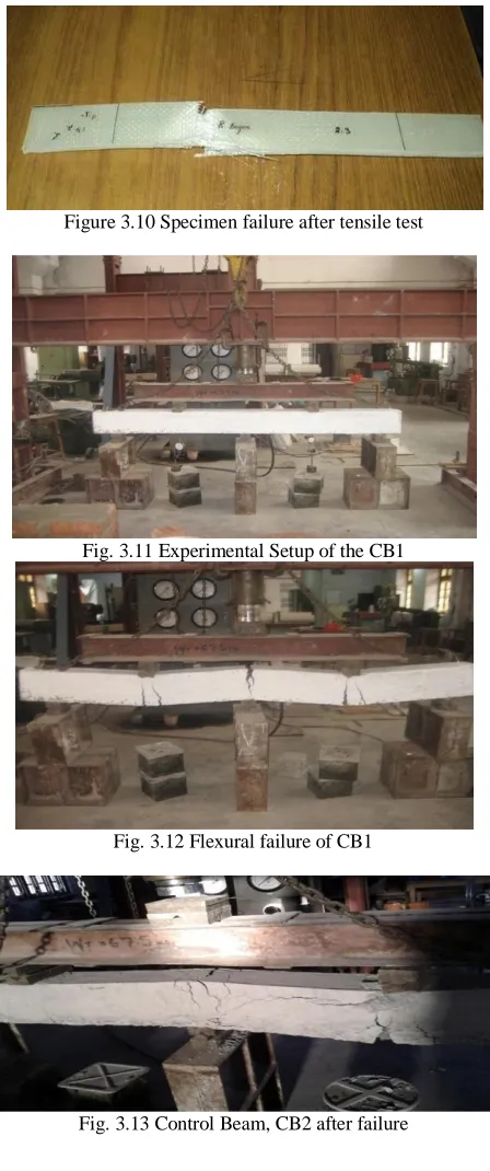
Plates of 2 layers, 4 layers, 6 layers and 8 layers were casted and six specimens from each thickness were tested.
Fig. 3.8 Specimens for tensile testing
Fig. 3.9 Experimental set up of INSTRON 1195
Figure 3.10 Specimen failure after tensile test
Fig. 3.11 Experimental Setup of the CB1
Fig. 3.12 Flexural failure of CB1
International Journal of Research
Available at
https://edupediapublications.org/journals
e-ISSN: 2348-6848
p-ISSN: 2348-795X
Volume 05 Issue 12
April 2018
Available online:
https://edupediapublications.org/journals/index.php/IJR/
P a g e
| 4343
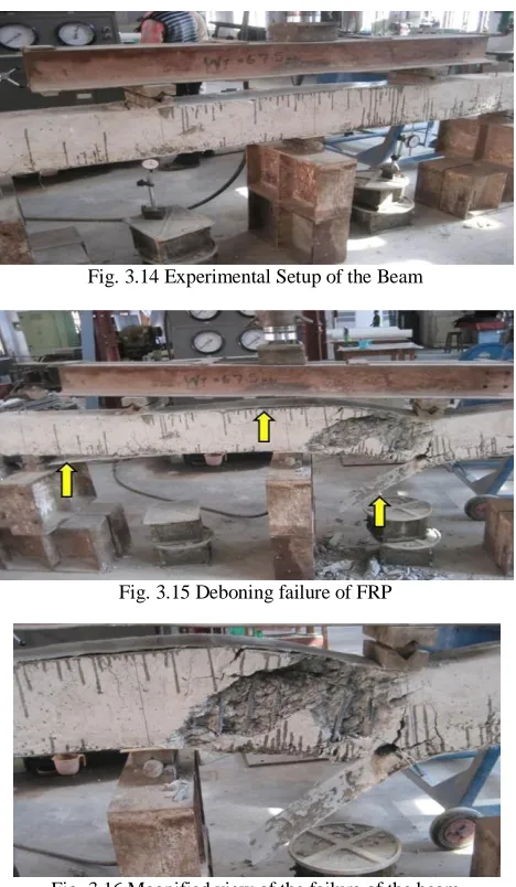
Fig. 3.14 Experimental Setup of the Beam
Fig. 3.15 Deboning failure of FRP
Fig. 3.16 Magnified view of the failure of the beam
Strengthened Beams (Sb2):
Single layer of U-wrap was applied on the beam to prevent flexural failure. Tensile rupture of FRP occurred at the mid section of both left and right
Span at lower loads and as the load increased, the beam failed in deboning with concrete cover as shown in Figure 3.17 and shear crack was developed below the FRP layer as shown in Figure 3.18.
Figure 3.17 Tensile rupture of FRP at mid section of right span at lower value of load
Figure 3.18 Ultimate failure of beam by deboning of FRP with concrete Cover
IV. EXPERIMENTAL RESULTS
Failure Modes Control Beam
The control beam CB1 and CB2 failed completely in flexure. The failure started first at the tension zone and then propagated towards the compression zone and finally failed in flexure.
Strengthened Beam
Generally, the rupture of FRP sheet was sudden and accompanied by a loud noise indicating a rapid release of energy and a total loss of load capacity. For all the strengthened beams, the failure modes for Series S1 and S2 are described in Table 4.1 & 4.2.
The following failure modes were examined for all the tested beams: Flexural failure
Deboning failure (with or without concrete cover) Tensile rupture
Rupture of the FRP laminate is assumed to occur if the strain in the FRP reaches its design rupture strain before the concrete reaches its maximum usable strain. GFRP deboning can occur if the force in the FRP cannot be sustained by the substrate. In order to prevent deboning of the GFRP laminate, a limitation should be placed on the strain level developed in the laminate.
Table 4.1 Experimental Results of the Tested Beams for Series S1
Failure Mode Pu (KN) =
Pu(strengthened beam)/ Pu(Control beam) CB1 Flexural failure 260 1.00 SB1 Debonding failure
International Journal of Research
Available at
https://edupediapublications.org/journals
e-ISSN: 2348-6848
p-ISSN: 2348-795X
Volume 05 Issue 12
April 2018
Available online:
https://edupediapublications.org/journals/index.php/IJR/
P a g e
| 4344
without concrete cover
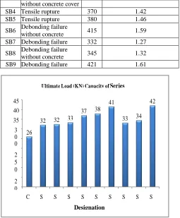
SB4 Tensile rupture 370 1.42 SB5 Tensile rupture 380 1.46 SB6 Debonding failure
without concrete 415 1.59 SB7 Debonding failure 332 1.27 SB8 Debonding failure
without concrete 345 1.32 SB9 Debonding failure 421 1.61
Fig. 4.16 Ultimate Load Capacity of Series S1 beams
Figure 4.17 Percentage increase in the Ultimate Load Carrying capacity of strengthened beams of S1 w.r.t CB1
V. CONCLUSION
The present experimental study is carried out on the flexural behavior of reinforced concrete rectangular beams strengthened by GFRP sheets. Fourteen reinforced concrete (RC) beams weak in flexure having different set of reinforcement detailing are casted and
tested. The beams were grouped into two series labeled S1 and S2. Each series had different longitudinal and transverse steel reinforcement ratios. From the test results and calculated strength values, the following conclusions are drawn:
The ultimate load carrying capacity of all the strengthen beams is higher when compared to the control beam.
The initial cracks in the strengthened beams are formed at higher load compared to control beam.
From series S1, beam SB9 which was strengthened by U-wrap and was anchored by using steel plate and bolt system, showed the highest ultimate load value of 415 KN. The percentage increase of the load capacity of SB9 was 61.92 %.
The load carrying capacity of beam SB6, which was strengthened by two layers of U- wrap of length 88 cm in positive moment zone and two layers of U-wrap of length 44 cm over first two layers, was 415 KN which was nearer to the load capacity of beam SB9. The percentage increase of load carrying capacity was 59.61 %, from which it can be concluded that applying FRP in the flexure zone is quite effective method to enhance the load carrying capacity.
TB3 beam from Series S2, which was strengthened by two layers of U-wrap in positive moment zone and two layers of U-wrap in flexure zone above first two layers, was having maximum ultimate load value of 326 KN, than the other strengthened beams of same category. The percentage increase of this beam was 63 % which was highest among all strengthened beams.
Using of steel bolt and plate system is an effective method of anchoring the FRP sheet to prevent the deboning failure.
Strengthening of continuous beam by providing U-wrap of FRP sheet is a new and effective way of enhancing the capacity of load carrying.
Flexural failure at the intermediate support section can be prevented by application of GFRP sheets.
SCOPE OF THE FUTURE WORK
It promises a great scope for future studies. Following areas are considered for future research:
Experimental study of continuous beams with opening.
Non linear analysis of RC continuous beam.
FEM modeling of unanchored U-wrap.
FEM modeling of anchored.
VI. REFERENCES
[1] ACI Committee 440, “Starte-of-the-art report on fiber reinforced plastic reinforcement for concrete structures”, Report ACI 440R-96, USA: American Concrete Institute, 1996.
[2] Aiello MA, Valente L, and Rizzo A, “Moment redistribution in continuous reinforced concrete beams strengthened with carbon fiber-reinforced polymer laminates”, Mechanics of Composite Materials, vol. 43, pp. 453-466, 2007.
[3] Aiello MA, and Ombres L, “Cracking and deformability analysis of reinforced concrete beams strengthened with externally bonded carbon fiber reinforced polymer sheet”, ASCE Journal of Materials in Civil Engineering, vol. 16, No. 5, pp.292-399,2004.
[4] Akbarzadeh H, and Maghsoudi AA, “Experimental and analytical investigation of reinforced high strength concrete continuous beams strengthened with fiber reinforced polymer”,
Materials and Design, vol. 31, pp. 1130-1147, 2010.
[5] Arduini M, and Nanni A, “Behavior of pre-cracked R. C.
Designation
of beams
S
B
9
S
B
8
S
B
7
S
B
6
S
B
5
S
B
4
S
B
3
S
B
2
S
B
1
2
0
1
0
0
2
5
23
.0
7
27
.6
9
28
.4
6
3
0
32
.6
9
4
0
4
2.
3
46
.1
5
6
0
5
0
59.
61
61
.9
2
7
0
Percentage increase in the Ultimate Load Carrying capacity w.r.t CB1
Designation of beams S B9 S B8 S B7 S B6 S B5 S B4 S B3 S B2 S B1 C B1 26 0 3 0 0 2 5 0 2 0 0 1 5 0 1 0 0 5 0 0 33 2 33 4 32 5 32 0 35 0 34 5 38 0 37 0 40 0 42 1 41 5 45 0
International Journal of Research
Available at
https://edupediapublications.org/journals
e-ISSN: 2348-6848
p-ISSN: 2348-795X
Volume 05 Issue 12
April 2018
Available online:
https://edupediapublications.org/journals/index.php/IJR/
P a g e
| 4345
Beams strengthened with carbon FRP sheets”, ASCE Journal of Composites for Construction, vol. 1, No. 2, pp. 63- 70, 1997. [6] Ashour AF, El-Refaie SA, and Garrity SW, “Flexural strengthening of RC continuous beams using CFRP laminates”,
Cement and Concrete Composites, vol. 26, pp. 765-775, 2003. [7] Bank LC, and Arora D, “Analysis of RC beams strengthened with mechanically fastened FRP (MF-FRP) strips”, Composite Structures, vol. 79, pp. 180–191, 2006.