Crosstalk Suppression by Applying Multilevel Transmission
Yafei Wang*, Yanxiao Zhao, and Xuehua Li
Abstract—Crosstalk is one of the bottlenecks in improving the speed and density of high-speed interconnection systems. In this paper, multi-way and 2-level transmission is changed to one-way and multi-level transmission. Under the condition to maintain the data transmission capacity of the system, the number of microstrip lines is reduced, and the distance between microstrip lines is increased to reduce crosstalk. The simulation results show that over 50% of crosstalk is suppressed in multilevel signal transmission systems.
1. INTRODUCTION
Crosstalk is one of the four problems in signal integrity. In high-speed interconnection system, the transmission performance of the signals in the multichannel has been seriously influenced by crosstalk [1– 3]. The physical factors of crosstalk include inductive and capacitive coupling between the aggressor lines and victim lines. When the transmission line works at the high frequency (i.e., high signal transmission rate), the rise time and fall time of the signals are short, it will lead to the transformation of instantaneous voltage and produce inductive and capacitive coupling, resulting in serious crosstalk. Moreover, the closer the two transmission lines are, the larger the inductance and capacitive coupling are produced, and it will result in more serious crosstalk between the two transmission lines. Crosstalk in aggressor line will become larger when multiple aggressor lines aggress one victim line especially in bus circuit model. There are many ways to reduce crosstalk on victim lines, such as reducing electromagnetic coupling between transmission lines to suppress crosstalk [4–8], or processing signals on transmission lines to reduce crosstalk [9–11]. The above solutions are commonly implemented by reducing the influence of crosstalk on the whole interconnection system, i.e., by eliminating interference of crosstalk on useful signals, but they are applied only to the 2PAM signals. In this paper, the influence of multi-level signal transmission on crosstalk is studied on signal integrity. Without changing the data transmission capability and bandwidth of the system, multi-level signal transmission is employed, and multi-channel 2-level transmission system is transformed into one-channel multi-level transmission system. The simulation results show that 4 level signal transmission can suppress more than 50% of crosstalk in the system under such conditions as the equal line width and line spacing.
2. TIME DOMAIN ANALYSIS FOR CROSSTALK
Figure 1 shows the crosstalk model considering signal coupling between two microstrip lines. The transmission line with noise source is called as aggressor line, whereas the noisy transmission line is considered as victim line. As shown in Figure 1, with no excitation signal at point b, the coupling output vd(t) at point dfor input signal va(t) at this point is crosstalk on victim line by the aggressor line.
Received 20 November 2018, Accepted 26 December 2018, Scheduled 8 January 2019
* Corresponding author: Yafei Wang ([email protected]).
Figure 1. Crosstalk model between the microstrip transmission lines.
According to [12], farend crosstalk of the two microstrip lines in parallel as shown in Figure 1 can be modeled as follows:
vd(t) = 1 2l
Z0Cm−
Lm Z0
dva(t)
dt (1)
It shows the transmission features from pointa on aggressor line to remote pointdon victim line without considering the second crosstalk, wherein Z0 is the characteristic impedance of transmission line; Cm is coupling capacity per unit length among transmission lines; Lm is coupling inductance per unit length among transmission lines;l is the coupling length of the transmission line.
As shown in formula (1), crosstalk is related to coupling length of transmission line, characteristic impedance, coupling capacity per unit length among transmission lines, coupling inductance per unit length among transmission lines, and differential of excitation signals. In general, coupling length of transmission line and characteristic impedance are fixed values. Therefore, crosstalk is related to coupling capacity per unit length among transmission lines, coupling inductance per unit length among transmission lines, and differential of drive signals. Following [13], the empirical formulas for the LC parameters are shown in Eqs. (2) and (3), andsrefers to distance between adjacent transmission lines.
Lm = μrμ0 4π ln
1 +
2h
s
2
H/m (2)
Cm = εrε0
4π KC1KL1
w
h 2
ln
1 +
2h s
2
F/m (3)
Therefore, coupling capacity per unit length among transmission lines and coupling inductance per unit length among transmission lines are related to distance among transmission lines as the thickness of base plate, dielectric constant and line width are fixed. The differential of excitation signals is related to rise time (fall time) of the signals as the signal level is inviable. Thus crosstalk is related to rise time (fall time) of excitation signals and the distance between the transmission lines.
3. CROSSTALK SUPPRESSION VIA MULTILEVEL TRANSMISSION
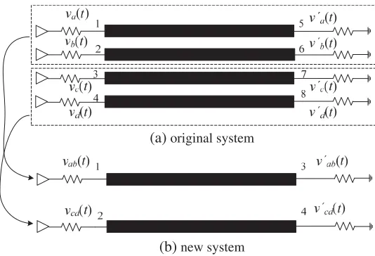
It is verified that crosstalk can be reduced by increasing distance among transmission lines [14], and the distance can be increased by employing multilevel transmission in condition that transmission capacity of system data, bandwidth, and system area in PCB plate are maintained. In fact, the one-channel multi-level transmission is substituted for multi-channel 2-level transmission, which saves the number of transmission lines, so the distance between transmission lines can be increased. It saves the quantity of transmission lines and makes the distance between the transmission lines wider.
(a)original system
(b)new system
Figure 2. Model of crosstalk suppression by applying multilevel transmission.
+A
-A
+A
-A
+3A
-A +A
-3A v (t) or v (t)
v (t) or v (t)
a c
b d
ab cd
v (t) or v (t)
Figure 3. Signal transformation from level 2 to level 4 transmission.
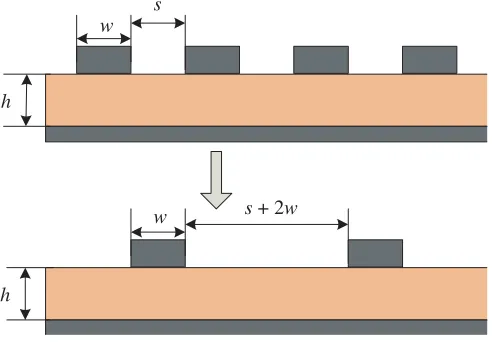
adjacent lines, resulting in suppressing the crosstalk. Each two-way data transmission in Figure 2(a) is changed into one-way in Figure 2(b). Each way in Figure 2(b) carries two-way data information in Figure 2(a). Correspondingly, the 2PAM signals va(t) and vb(t) are transferred into one-way 4PAM signal vab(t), the 2PAM signals vc(t) and vd(t) are also changed into one-way 4PAM signal vcd(t). It should be noted that the width of code element in Figure 2(b) is same as that in Figure 2(a), so are the system bandwidth and the quantity of information. The principle that two 2PAM signals are transferred into a 4PAM is shown in Figure 3. The comparison of the distance between the two adjacent lines in Figures 2(a) with 2(b) shows that two transmission lines have been reduced in the circuit plate. Line widthwremains unchanged but the distance between the two adjacent lines is widened fromstos+ 2w.
As shown in Figure 3, the PAM signal can be expressed by the the following expression
v(t) =
∞
n=−∞
angT(t−nTs) (4)
wherein{an}refers to generalized and smooth random sequence;gT(t−nTs) refers to output waveform of pulse forming filter; and Ts refers to interval of code elements. In general, {an} is considered as±A
In conclusion, two 2PAM signals are transferred into one 4PAM, and two transmission lines can be reduced in the circuit plate, so the distance between the two adjacent lines is widened, and in the end the crosstalk is suppressed. Crosstalk can be suppressed by increasing the distance between the adjacent lines as shown in Figure 4.
w
h
w
h
s
s + 2w
Figure 4. Side view of PCB plate of level 2 to level 4 transmission.
4. SIMULATION RESULTS AND ANALYSIS
The validity of proposed method is verified by utilizing advanced design system (ADS) software. The MACLIN4 of TLines-Microstrip has been used to create four microstrip lines in parallel. The parameters are set as follows: width of microstrip line w = 40 mil, distance between adjacent microstrip lines
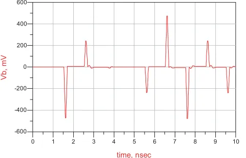
s = 40 mil, medium height h = 22 mil, dielectric constant εr = 4.5, magnetic permeability μr = 1, dielectric loss angle tangent tanδ = 0.02, and length of microstrip line l = 4 inch. The conductor is copper. In addition, the characteristic impedance of microstrip line is 50 Ω. The circuit is arranged as shown in Figure 5(a). The transmission rate of input data through microstrip line is set as 1 G bit/s. The crosstalk from two middle microstrip lines is the most serious. From the view of influences on overall system by crosstalk, farend crosstalk in port 6 shall be simulated. Excitation signals are input from ports 1 and 3, and output signal vb(t) in port 6 is the farend crosstalk, simulation results are shown in Figure 6. Similarly, simulation of level 4 transmission is conducted based on above parameters. Circuit layout is shown in Figure 5(b). Two 2PAM signals are transferred into one 4PAM, and the distance between adjacent microstrip lines s+ 2w = 120 mil. The transmission rate of input data through microstrip line is set as 1G Band. When level 4 simulation signal is added for port 1 as shown in Figure 5(b), output signal vcd(t) in port 4 is the farend crosstalk. The simulation results are shown in Figure 7. According to the comparison of Figures 6 with 7, the distance between the adjacent transmission lines is increased, and the crosstalk decreases from 475 mV to 235 mV, over 50% crosstalk is reduced. Two microstrip lines are saved when level 4 transmission is used.
v´b(t)
v´cd(t) 1 2 3 4 5 6 7 8 2 1 3 4 2PAM 2PAM 4PAM
va(t)
vc(t)
vab(t)
va(t)
vab(t) vc(t)
+0.5V -0.5V +0.5V -0.5V +1.5V -1.5V +0.5V -0.5V
(a)Circuit simulation model for 2PAM
(b)Circuit simulation model for 4PAM
Figure 5. Circuit simulation model.
1 2 3 4 5 6 7 8 9
0 10 -400 -200 0 200 400 -600 600 time, nsec Vb, mV
Figure 6. Simulation results of Figure 5(a).
1 2 3 4 5 6 7 8 9
0 10 -400 -200 0 200 400 -600 600 time, nsec Vc d , mV
Figure 7. Simulation results of Figure 5(b).
5. CONCLUSION
Crosstalk suppression by multilevel signal transmission has been researched. The simulation results show the validity of crosstalk suppression. It saves lines to employ the multilevel signal transmission and simultaneously suppress over 50% crosstalk in the condition that transmission capacity of information and bandwidth remain unchanged. The research results can provide technical reference to suppress crosstalk in high-speed interconnection system.
ACKNOWLEDGMENT
This work is supported by the Young Scientists Fund of the National Natural Science Foundation of China (Grant No. 61601038).
REFERENCES
4. Lee, K., H. Jung, H.-J. Chi, et al., “Serpentine microstrip line with zero far-end crosstalk for parallel high-speed DRAM interfaces,”IEEE Transactions on Advanced Packaging, Vol. 33, No. 2, 552–558, 2010.
5. Wu, B. and T. Mo, “Barbed transmission lines for crosstalk suppression,”Asia-Pacific Symposium on Electromagnetic Compatibility (APEMC), 621–624, Singapore, May 21–24, 2012.
6. Xu, J. and S. Wang, “Investigating a guard trace ring to suppress the crosstalk due to a clock trace on a power electronics DSP control board,”IEEE Transactions on Electromagnetic Compatibility, Vol. 57, No. 3, 546–554, 2015.
7. Huang, B., K. Che, and C. Wang, “Far-end crosstalk noise reduction using decoupling capacitor,”
IEEE Transactions on Electromagnetic Compatibility, Vol. 58, No. 1, 1–13, 2016.
8. Refaie, M. I., W. S. El-Deeb, and M. I. Abdalla, “A study of using graphene coated microstrip lines for crosstalk reduction at radio frequency,” Proceedings of the 35th National Radio Science Conference (NRSC), 85–90, Cairo, Egypt, March 20–22, 2018.
9. Oh, T. and R. Harjani, “Adaptive techniques for joint optimization of XTC and DFE loop gain in high-speed I/O,”ETRI Journal, Vol. 37, No. 5, 906–916, 2015.
10. Wang, Y. and X. Li, “Crosstalk cancellation method based on unitary transformation of coupled transmission lines-channel transmission matrix,” Progress In Electromagnetics Research Letters, Vol. 52, 45–50, 2015.
11. Aprile, C., A. Cevrero, P. A. Francese, et al., “An eight-lane 7-Gb/s/pin source synchronous single-ended RX with equalization and far-end crosstalk cancellation for backplane channels,”IEEE Journal of Solid-State Circuits, Vol. 53, No. 3, 861–872, 2018.
12. Young, B., Digital Signal Integrity: Modeling and Simulation with Interconnects and Packages, Prentice Hall, New Jersey, 2001.
13. Ernesto, J. and R. S´anchez, “A frequency-domain approach to interconnect crosstalk simulation and minimization,” Microelectronics Reliability, Vol. 44, No. 4, 673–681, 2003.