A Phase Diversity Printed-Dipole Antenna Element for Patterns
Selectivity Array Application
Fukun Sun*, Fushun Zhang, and Chaoqiang Feng
Abstract—A phase diversity printed-dipole antenna element for patterns selectivity array application is designed in this paper. The antenna element consists of a printed dipole structure and two varactors. By changing the control voltage of each element, various radiation phases in the far field of each element is realized, that is, the peak gain direction of the array is changed. With this method, the structure designed is simple, and only two varactors are loaded. To verify the feasibility, an antenna prototype is experimentally characterized, which validates the proposed concept. The impedance bandwidth of array is 22.2% (3.2∼4.0 GHz), in which the peak gain direction can be scanned during angles from −θ
to +θ across broadside (θ= 13◦ ∼18◦ at different frequencies). It can be applied to phased antenna system.
1. INTRODUCTION
In recent years, the requirements for reconfigurable antennas are continuously increasing. Under the same aperture, the flexible and variable performance of reconfigurable antennas meets the additional requirements of various modern wireless communications. Especially, the pattern reconfigurable antenna is a popular research direction in reconfigurable antennas. Generally, reconfigurable patterns include three beam forms: broadside and conical switchable beams [1–3], azimuth switchable beams [4–6] and elevation switchable beams [7–10]. In this paper, reconfigurable antennas of switchable beams in elevation are discussed, compared and designed.
In [7], the main beams can be selected to five directions by choosing the switchable director and switchable reflector. However, its structure is so complex that it is not suitable for forming an array. In [8, 9], two microstrip antennas are designed by switchable directors with a simple structure, but the impedance bandwidth of 5.6% and 1.7% is not appropriate for wideband systems. In [10], various far-field phases are realized by loading varactors and branches to achieve a continuous beam-steerable radiation pattern covering scanning during angles from −23◦ to +23◦ across broadside. However, due to the larger structure of branches, the aperture of antenna element is increased, and it is not suitable for two-dimensional array. Therefore, it is necessary to design a pattern reconfigurable antenna array of switchable beams in elevation for the phased antenna system.
In this paper, a two-element array is designed to scan in elevation plane by controlling two varactors in the dual arm structure of dipole. The working bandwidth of the array is 22.2%, and the peak gain direction can be scanned during angles from −θ to +θ across broadside (θ = 13◦ ∼ 18◦ at different frequencies in the bandwidth). It is simple in structure and convenient for array formation, so it is suitable for phased antenna system. The remainder of this paper is organized as follows. The antenna configuration and detailed design are depicted in the second section. Then, a prototype is simulated, manufactured, and measured in the third section. Finally, a conclusion is given in the last section.
Received 22 July 2018, Accepted 6 September 2018, Scheduled 17 September 2018 * Corresponding author: Fukun Sun ([email protected]).
2. ANTENNA DESIGN AND CHARACTERISTICS
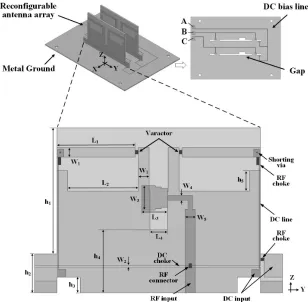
It can be seen that the antenna array includes two reconfigurable antenna elements and a metal ground in Figure 1. The board of FR4 is selected as dielectric substrate for both elements and ground with a relative permittivity of 4.4, loss tangent of 0.02 and thickness of 1.5 mm. In order to facilitate the installation, the metal reflector is trenched and fixed to the antenna element. The direct current (DC) bias circuit is printed on the upper surface of the ground, which is easy to be welded with the DC bias circuit of the element. In addition, A, B and C are the soldering points of the external circuit. The element consists of a printed dipole and two sets of varactors. By controlling the voltage of A, B and C points, the capacitance of the varactors is changed. As a result, the phase of the two antenna elements is changed in the far-field radiation in real time. Therefore, the scanning pattern of the array in elevation plane is realized. The specific structural parameters of the antenna array are given in Table 1.
Figure 1. Design for the reconfigurable antenna.
Table 1. Antenna dimensions.
Parameter Value (mm) Parameter Value (mm)
L1 20.2 W4 1.2
L2 18.2 W5 2.6
L3 6.7 h1 32.5
L4 4.6 h2 10.0
W1 2.5 h3 4.0
W2 0.1 h4 16.3
In order to better explain the working mode, the parameters of the antenna are analyzed by ANSYS HFSS software. In Figure 2, five curves of far-field radiation phase varying with capacitance are given at five frequency points (3.2 GHz, 3.4 GHz, 3.6 GHz, 3.8 GHz and 4.0 GHz). It can be seen that the capacitance value is in the range of 0.15 ∼1.30 pF, and the phase change at 3.2 GHz is the maximum of ∆ϕ ≈ 31.7◦ (ϕ means the far-field radiation phase of antenna element), while the phase change decreases with the increase of frequency. So different elements can be designed to get a phase diversity by changing the capacitance of varactors, which can form a patterns selectivity array. In Figure 3, VSWRs of antenna elements corresponding to different capacitance values are given, respectively. It can be seen that when the varactors operate in the range of 0.15∼1.30 pF, the VSWRs of antenna are stable in the range of 3.2∼4.0 GHz.
Figure 2. Relative phase of the far-field radiation as a function of the varactor capacitance at different frequencies. The maximum achievable phase difference ∆φ is highlighted.
Figure 3. Simulated VSWRs of the proposed antenna at different capacitance values.
In addition, in order to facilitate testing and verification, three typical working modes corresponding to voltage configuration are given in Table 2. The two RF inputs are excited in equal amplitude and phase in all cases. When the voltage of A, B and C ports is 0 V, the peak gain direction is 0◦(broadside). When the voltage of A and B ports is 0 V and the voltage of C port 18 V, the peak gain direction is −θ
(θ= 13◦∼18◦ at different frequencies). Similarly, the direction scan of +θcan also be achieved.
Table 2. Configurations of the A, B and C ports of three typical modes.
Mode A Port B Port C Port Peak Gain Direction
Case 1 0 V 0 V 0 V 0◦ (Broadside)
Case 2 0 V 0 V 18 V −θ (θ= 13◦ ∼18◦)
Case 3 0 V 18 V 0 V +θ (θ= 13◦ ∼18◦)
3. EXPERIMENTAL RESULTS AND COMPARISON
Figure 4. Measured and simulated VSWRs and Gains of the proposed antenna.
(a) (b)
(e) (f)
Figure 5. Measured and simulated radiation patterns of (a) H-plane, (b) E-plane at 3.2 GHz and (c)
H-plane, (d) E-plane at 3.6 GHz and (e) H-plane, (f)E-plane at 4.0 GHz.
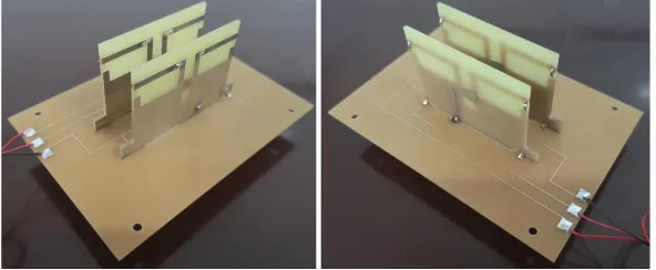
Figure 6. Fabricated reconfigurable antenna array.
reflection coefficients were measured using the Wiltron 37269A Network Analyzer, and the radiation patterns were measured by the time-gating method. The comparison method is used to measure the realized gain. Then, the simulated and measured results of VSWRs and gain are all given in Figure 4. Additional, Figure 5 shows the directional patterns including the XOZ and Y OZ plane patterns at 3.2 GHz, 3.6 GHz and 4.0 GHz.
Varactor (MA46H120) is used with a measured capacitance ranging from 0.149 pF to 1.304 pF, controlled by a reverse bias voltage from 18 V to 0 V. The other components are selected as follows: Inductor (220 nH) is adopted in the DC-biasing circuits for RF choker; Capacitor (22 uF) acts as RF connector.
In Figure 4, it is known that the simulated and measured results of VSWRs and gain coincide. The impedance bandwidth is 22.2% (3.2∼4.0 GHz), and the stability gain is more than 6.3 dBi. In Figure 5, the simulation of the pattern is also consistent with the measured results. So different elements can be designed to get phases diversity by changing the capacitance of varactors, which can form a patterns selectivity array. Diversity performance is achieved as follows. At beginning of the band, the radiation direction of pattern is at θ =−13◦, and the gain is 7.0 dBi with the 27.8 dB of the cross polarization. At center of the band, the radiation direction of pattern is at θ = −17◦, and the gain is 6.9 dBi with the 28.0 dB of the cross polarization. At end of the band, the radiation direction of the pattern is at
4. CONCLUSION
In this paper, a pattern reconfigurable antenna array with two elements is designed. The peak gain direction can be adjusted in elevation plane, and a continuous beam-steerable radiation pattern covering scanning during angles from −θ to +θ across broadside is achieved (θ = 13◦ ∼ 18◦ at different frequencies). The measured results of the antenna agree well with the simulated ones. The impedance bandwidth is 22.2% (3.2 ∼ 4.0 GHz), and the gain is stable over 6.3 dBi, which can be applied to a phased antenna system.
REFERENCES
1. Row, J. S. and Y. J. Huang, “Reconfigurable antenna with switchable broadside and conical beams and switchable linear polarized patterns,”IEEE Transactions on Antennas and Propagation, Vol. 66, No. 7, 3752–3756, Jul. 2018.
2. Lin, W., H. Wong, and R. W. Ziolkowski, “Wideband pattern-reconfigurable antenna with switchable broadside and conical beams,” IEEE Antennas and Wireless Propagation Letters, Vol. 16, 2638–2641, 2017.
3. Qin, P. Y., Y. J. Guo, A. R. Weily, and C. H. Liang, “A pattern reconfigurable U-slot antenna and its applications in MIMO systems,”IEEE Transactions on Antennas and Propagation, Vol. 60, No. 2, 516–528, Feb. 2012.
4. Fayad, H. and P. Record, “Multi-feed dielectric resonator antenna with reconfigurable radiation pattern,”Progress In Electromagnetics Research, Vol. 76, 341–356, 2007.
5. Alam, M. S. and A. Abbosh, “Planar pattern reconfigurable antenna with eight switchable beams for WiMax and WLAN applications,”IET Microwaves, Antennas &Propagation, Vol. 10, No. 10, 1030–1035, Jul. 2016.
6. Yang, Y., R. B. V. B. Simorangkir, X. Zhu, K. Esselle, and Q. Xue, “A novel boresight and conical pattern reconfigurable antenna with the diversity of 360◦ polarization scanning,” IEEE Transactions on Antennas and Propagation, Vol. 65, No. 11, 5747–5756, Nov. 2017.
7. Chen, S. L., P. Y. Qin, W. Lin, and Y. J. Guo, “Pattern-reconfigurable antenna with five switchable beams in elevation plane,”IEEE Antennas and Wireless Propagation Letters, Vol. 17, No. 3, 454– 457, Mar. 2018.
8. Deng, W. Q., X. S. Yang, C. S. Shen, J. Zhao, and B. Z. Wang, “A dual-polarized pattern reconfigurable Yagi patch antenna for microbase stations,” IEEE Transactions on Antennas and Propagation, Vol. 65, No. 10, 5095–5102, Oct. 2017.
9. Jusoh, M., T. Sabapathy, M. F. Jamlos, and M. R. Kamarudin, “Reconfigurable four-parasitic-elements patch antenna for high-gain beam switching application,” IEEE Antennas and Wireless Propagation Letters, Vol. 13, 79–82, 2014.