Dual-Function MIMO Radar-Communications Employing
Frequency-Hopping Chirp Waveforms
Shaddrack Y. Nusenu*, Wen-Qin Wang, and Hui Chen
Abstract—A dual-function radar-communication system is a technology equipped with a joint platform that enables performing a radar function (primary function) and a communication function (secondary function) simultaneously. This duality has become increasingly necessary, since it alleviates congestion and ease competition over frequency spectrum. In this paper, we put forward a technique for information embedding, specifically to multiple-input multiple-output (MIMO) radar employing frequency-hopping chirp (FHC) waveforms. We use FHC codes to implement the primary function (i.e., MIMO radar operation), while embedding communication symbol, for example, phase shift keying (PSK), in each FHC code for secondary function (i.e., communication operation). We show that the communication operation does not interfere with the MIMO radar function. In addition, standard ratio testing is used at the communication receiver to detect the embedded PSK symbols. Furthermore, the waveform designed has the superiorities of high range resolution, constant time domain and almost constant frequency-domain modulus, large time-bandwidth product, and low time-delay and frequency-shift correlation peaks. Numerical results show that: 1) data rates can be accurately detected, and thus, several Mbps are achieved in the system; 2) the SER performance characteristics are significantly improved; 3) the orthogonal frequency-hopping chirp waveforms achieve better range and Doppler resolution with reduced sidelobes levels compared to that of conventional frequency hopping waveforms.
1. INTRODUCTION
The concept of coexistence of radar and communications on a single platform has been proposed as a solution to the radio frequency spectrum congestion and also attracted a lot of attention [1, 2]. Since there has been a huge demand from communication operators, the competition between the radar and communication in terms of frequency spectrum could be eased by allowing both systems to share the same resources and operate simultaneously from a single platform [3–16]. This implies that we can achieve an efficient utilization of the limited frequency spectrum resources. Recently, the concept of dual-function radar-communication (DFRC) has been proposed [16]. The main idea about this concept is to utilize identical signals and the same antenna array for both radar (primary function) and communication (secondary function) operations simultaneously. A number of papers [16–25] have investigated the capabilities of dual-function radar-communication (DFRC) system. DFRC systems utilize the full potential of radar resources, for instance, high quality hardware and high transmit power. Embedding information into the radiation of single-input multiple-output (SIMO) radar can be done by employing the following: 1) waveform diversity, 2) sidelobe control, and 3) time modulated array.
Lately, information embedding into the radiation of multiple-input multiple-output (MIMO) radar has been reported in [23–25]. MIMO radar can provide more degrees-of-freedom, but correspondingly
Received 17 October 2017, Accepted 14 January 2018, Scheduled 8 February 2018 * Corresponding author: Shaddrack Yaw Nusenu ([email protected]).
more orthogonal waveforms are needed for the system, thus one might argue that the enhanced performance cannot be realized unless we fully address the waveform diversity design problem. It is assumed that, in an MIMO radar system, the waveforms must be separable from each other, and their returns should be sufficiently coherent for the post-processing [26]. More specifically, both the transmitted and received signals should remain orthogonal under the Doppler shifts caused by target motions [27]. However, most of existing papers do not fully address the impacts of Doppler shifts in waveform diversity design. Moreover, low peak-to-average power ratio (PAPR) and large time-bandwidth product are also desired for the waveforms in order to generate maximum output power and to ensure a stable output power level for amplitude variations in the high-power amplifier input signal. A chirp waveform is widely used in various radar systems due to its attractive properties, such as high range resolution, constant modulus, Doppler tolerance and implementation simplicity. From a practical point of view, we think that MIMO radar should use chirp-based waveforms. The up- and down-chirp waveforms are used in [28], but there are only two orthogonal waveforms. An OFDM chirp waveform design scheme is proposed in [29], which allows the generated waveforms to occupy common spectral support and thereby enables them to exploit the full bandwidth. Although it can be easily extended to generate more than two waveforms, the waveforms will generate large grating lobes due to sparse sampling effects [30].
In this work, we extend the work in [23] using frequency-hopping waveforms to frequency-hopping chirp waveforms. The objective is to embed modulation schemes (i.e., BPSK, QPSK, PSK) into the radiation of MIMO radar employing frequency-hopping chirp waveforms. We adopt phase-rotation technique in [23] to embed communication symbols through the frequency-hopping chirp orthogonal transmit waveforms of the MIMO radar. It should be noted that the main advantages of the proposed waveform (i.e., frequency-hopping chirp) design can be summarized as follows: 1) All the advantages of chirp waveform such as large time-bandwidth product and Doppler tolerance are preserved in the designed waveforms. Moreover, the use of a chirp-like waveform allows the generated waveforms to maintain the chirp waveform ambiguity properties, namely a diagonal Doppler/range ambiguity function and low sidelobes. 2) The waveforms will remain orthogonal under arbitrary delays and Doppler shifts, while the impact of time delays and Doppler shifts are often ignored in existing MIMO radar waveform diversity design methods. We analyze the data rate for the proposed scheme, and in addition, performance evaluation is also provided in terms of symbol error rate (SER) and radar ambiguity function. The numerical results are compared with [23]. It is shown clearly that the proposed scheme outperformed [23] in the quality of the results.
The rest of the paper is organized as follows. Section 2 presents the signal model of MIMO radar. In Section 3, we introduce frequency-hopping chirp waveforms design for MIMO radar. Section 4 presents a communication embedding signaling scheme by utilizing frequency-hopping chirp waveforms. Section 5 introduces MIMO radar ambiguity function of the proposed waveform design. Numerical results are presented in Section 6, and finally, conclusions are drawn in Section 7.
2. SIGNAL MODEL OF COLOCATED MIMO RADAR
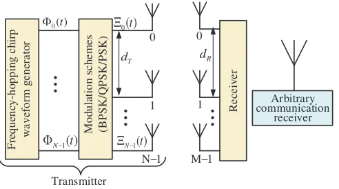
In this section, we consider a colocated MIMO radar-communications dual-function system consisting of transmitting antennasN and receiving antennasM. The interspacings of transmitting and receiving antennas are represented bydT anddR, respectively. We assume that the radar setup is monostatic, thus, the radar receiver and joint radar-communication transmitter are closely spaced so that both arrays would view the target from the same spatial direction in the far field. Fig. 1 shows the application scenario of MIMO dual-function transmitting system for both radar and communication operation employing frequency-hopping chirp waveforms and modulation scheme (i.e., BPSK/QPSK/PSK).
Suppose that L targets of interest exist in the far field of the MIMO radar. TheM ×1 complex-valued vector of the received baseband signal model is given by
xn(t, τ) =
L−1
l=0
αl(τ) (a∗(θl) Φn(t))b(θl) +wn(t, τ) (1)
where τ is the radar pulse number, l = 0,1, . . . , L−1, αl(τ) the reflection coefficient linked with the
Re
ce
iv
e
r
0( )t Φ
1( )
N− t
Φ
0( )t
Ξ
1( )
N− t
Ξ
T
d dR
F re que nc y-ho ppi n g c h ir p w a v efo rm g e n era to r 0 M o d u la tio n s c h e m e s (BPSK/Q PSK/PSK ) Arbitrary communication receiver 1
N−1
0
1
M−1
Transmitter
...
...
...
Figure 1. Application scenario of MIMO dual-function radar-communication operation using frequency-hopping chirp waveform and modulation schemes (BPSK/QPSK/PSK).
normal random process with covarianceσn2INM, Φn(t) the orthogonal transmitted signal waveform from the nth array element (n = 0,1, . . . , N −1), and (·)∗ the conjugate transpose. The transmitting and receiving steering vectors can be denoted as a(θl) and b(θl), respectively. From Eq. (1), we assume that the reflection coefficient αl(τ) remains constant during the entire pulse period; however, this pulse varies independently, which is similar to Swerling II target model [31].
3. MIMO RADAR USING FREQUENCY-HOPPING CHIRP (FHC) WAVEFORMS
One essential radar requirement is the high average transmitting power for the transmitted waveforms. Since radar is the primary function of the dual function system, theN transmitting waveforms should be designed with the following properties: 1) a large time-bandwidth product and a low peak-to-average ratio, 2) low cross-correlation interferences (see [32–35] and references therein), 3) a good peak-to-sidelobe ratio (PSLR) in the impulse response, 4) good ambiguity function characteristics such as range resolution, Doppler resolution, and matched filtering sidelobe performance, and 5) constant-modulus. This constant-modulus is essential because radar amplifiers generally work in a saturation condition, which prohibits amplitude modulation in radar waveforms. It is important to mention that the designed waveform should be orthogonal as possible. However, since perfect waveform orthogonality cannot be developed and implemented in real-life hardware, the orthogonality used in this paper refers to pseudo-orthogonal, namely, low-cross-correlation interferences. Frequency-hopping chirp waveform proposed in this paper possesses the above properties, and in addition, it is simple to generate and immune to interference. Therefore, the proposed frequency-hopping chirp waveform is suitable for MIMO radar operation.
The FHC waveforms during one radar pulse is given by
Φn(t) =
Q−1
q=0
expj2πcn,qΔf t+πkrt2s(t−qΔt) (2)
with
s(t) =
1, t∈[0,Δt),
0, otherwise. (3)
where cn,q ∈ {0,1, . . . , K−1} denotes the frequency-hopping code with n = 0,1, . . . , N −1 and
q = 0,1, . . . , Q−1, Q the code length, Δf the frequency-hopping step, kr the chirp rate, and Δt
the subchirp duration. Then, the waveform duration isTp =QΔt, and the bandwidth is approximately given as BW ≈(K−1) Δf + 1/Δt, where K is the number of frequencies. Specifically, when kr = 0, Eq. (2) is simplified to the conventional frequency-hopping waveform [36, 37]. Additionally, we impose the following conditions for waveform orthogonality at zero lag: cn,q could be constrained to satisfy
Orthogonal waveforms result in a uniform gain in all directions, which is a key aspect of detection using MIMO radars.
At the MIMO radar receiver, using matched filtering, the received signal components associated with the individual transmitted waveforms can be obtained. Therefore, matched filtering xn(t, τ) to each waveform Φn(t) yields
y(τ)
Tpxn(t, τ) Φ∗n(t)dt
Tp|Φn(t)|
2
dt (5)
=
L−1
l=0
αl(τ) (a(θl)⊗b(θl)) + ˆw(τ) (6)
where⊗ denotes the Kronecker product, and ˆw(τ) is given as
ˆ
wN−1(τ)
wT0 (τ),wT1 (τ), . . . ,wTN−1(τ)T (7)
which is the N M ×1 additive zero-mean noise term with covariance σz2INM, and INM is the identity matrix of size N M×N M.
4. WAVEFORM PHASE-ROTATION FORMULATIONS AND INFORMATION EMBEDDING METHOD
Analogous to [23], we develop the phase-rotation scheme as well as communication information embedding technique for our proposed FHC waveforms.
4.1. Formulations of Waveform Phase-Rotation Approach
Suppose that N ×1 vector of phase-rotations is defined as ψ = (exp(jψ0), . . . ,exp(jψN−1))T, where ψn,q ∈ [0, 2π] denote arbitrary phases with n = 0,1, . . . , N −1 and q = 0,1, . . . , Q−1. The phase-modulated waveform Ξn(t), n= 0,1, . . . , N−1 can be expressed as
Ξn(t) =
Q−1
q=0
exp (jψn,q) expj2πcn,qΔf t+πkrt2s(t−qΔt) (8)
Suppose that subchirp duration Δt is selected and that the following condition is satisfied Δt
0
expj2πcn,qΔf t+πkrt2expj2πcn,qΔf t+πkrt2dt= 0, n=n, q=q (9)
It should be noted that the phase-modulated waveforms Ξn(t), n = 0,1, . . . , N − 1 are also orthogonal, which can be verified easily using Eqs. (2) and (9).
Assume that during a particular radar pulse, we transmit the phase-modulated waveforms Ξn(t),
n= 0,1, . . . , N−1 as depicted in Fig. 1. Then, the radar received signal (i.e.,M ×1 complex vector)
can be described as
˜
xn(t, τ) =
Q−1
l=0
αl(τ) (a∗(θl) Ξn(t))b(θl) +wn(t, τ) (10)
Matched-filtering the received signal in Eq. (10) to each of the waveforms Ξn(t) yields
˜
y(τ)
Tpx˜n(t, τ) Ξ∗n(t)dt
Tp|Ξn(t)|
2
dt (11)
Rewrite Eq. (11) as Eq. (12)
˜
y(τ) =
Q−1
l=0
where ¯w(τ) is the N M ×1 zero-mean complex normal random process with covariance σw2INM and given by
¯
wN−1(τ)
wT0 (τ),wT1 (τ), . . . ,wTN−1(τ)T (13)
It can be seen that Eq. (6) and Eq. (12) yield the same signal models at the MIMO radar receiver. This means that Eq. (8) does not affect the operation of the MIMO radar receiver sensing performance.
4.2. Information Embedding Method
The phases ψn,q are employed as modulation symbols, for example (BPSK, QPSK, PSK) in order to embed information into the MIMO radar radiation. Thus, during each radar pulse, N symbols of communication can be embedded. Herein, we use PSK modulation scheme as an example. Note that the scheme can be extended to any modulation schemes for specific applications. We denote B
as bits of binary information representing each PSK symbol. Then, the actual binary sequence of information that requires to be embedded during the τth pulse is used to select the phase symbols
ψn,q(τ) n = 0,1, . . . , N −1, q = 0,1, . . . , Q−1 from a predefined constellation of unique symbols
(V = 2B). Without loss of generality, suppose that the constellation is distributed uniformly within the interval [0,2π], which correspond to
ΨP SK = [0, 2π/V, . . . ,2π(V −1)/V] (14)
The phase-modulated set of orthogonal waveforms during theτth pulse can be written as
Ξn(t, τ) =
Q−1
q=0
exp (jψn,q(τ)) expj2πcn,qΔf t+πkrt2s(t−qΔt) (15)
whereψn,q(τ)∈ΨP SK,n= 0,1, . . . , N−1. We assume that a communication system is equipped with a single receiving element which is located at an arbitrary direction (θcom). Therefore, the output signal at the communication receiver can be described as
Rcom(t, τ) =βCHdiag (a(θcom))Ξn(t, τ) +u(t, τ) (16)
where βCH denotes the channel coefficient of the propagation environment between the MIMO radar transmitting array and the communication receiver, andu(t, τ) is the interference and noise (i.e., white Gaussian with zero mean and varianceσu2). The channel coefficient βCH is assumed to remain constant during the entire coherent processing interval (CPI). Additionally, we assume an accurate estimation of the channel coefficient at the communication receiver side. The signal-to-noise ratio (SNR) at the communication receiver is SN R= 10 log(|βCH|2/σu2).
The communication receiver is assumed to have perfect knowledge of the FHC codecn,q, frequency-hopping step Δf and chirp rate kr. Also, it is assumed that the phase synchronization between the joint transmit platform and the communication receiver is adjusted. Matched-filtering the received signalRcom(t, τ) to the FHC subpulses yields
yn,q(τ) = Δt
0
Rcom(t, τ) exp−j2πcn,qΔf t+πkrt2s(t−qΔt) (17)
= βCHa[n]exp (ψn,q(τ)) +un,q(τ) (18)
wherea[n]exp(−j2πdnsinθcom) represents thenth entry ofa(θcom),dnthe displacement between the first and nth elements of the transmit array, and un,q(τ) the additive noise term at the output of the (n, q)-th matched filter with zero mean and variance σ2u, and given by
un,q(τ) Δt
0
u(t, τ) exp−j2πcn,qΔf t+πkrt2s(t−qΔt) (19)
θcom. Moreover, the communication receiver knows its physical arrangement of the transmitting array elements as well as the displacement of the transmitting array elements from the reference element. This information enables the communication receiver to cancel the phase term exp(−j2πdnsinθcom) before it proceeds to detect the embedded phase symbol ψn,q(τ).
4.3. Symbol Detection and Data Rate for Communication
Let us assume that the channel is estimated accurately. In real practical scenario, training sequences can be utilized to update the channel estimate periodically and adjust phase synchronization between the transmitting array and the communication receiver. The embedded phase symbols can be estimated as
˜
ψn,q(τ) =angle(yn,q(τ))−angle(βCH) + 2πdnsinθcom (20)
where angle(·) represents the angle of a complex number, and βCH denotes the phase of the channel coefficient. Once the embedded phase is estimated, the communication receiver compares the estimates to the dictionary ΨP SK to find the embedded communication symbols and convert them into the corresponding binary sequence.
It should be noted that the number of phase symbols which can be embedded during a single pulse repetition interval (PRI) equals that the number of transmitting antennasN is multiplied by the length of the FHC coding sequence. Therefore, the achievable data rateDrate in bits per second (bps) can be expressed as
Drate= log2(V) [N ·Q·P RF] (21) Note that a data rateDrate in the range of several Mbps can be achieved in this proposed system.
5. MIMO RADAR AMBIGUITY FUNCTION USING FREQUENCY-HOPPING CHIRP WAVEFORMS
Radar ambiguity function (AF) is a tool used to determine the delay and Doppler resolution of radar. The value of this AF is maximum at (˜τ , v) = (0,0), and it denotes the matched filter output without any mismatch. Hence, the narrower the AF around origin is, the sharper the range and Doppler resolution is. It is important to note that the choice of the design transmitted waveforms affects the range, Doppler and angular resolutions of the radar system [38–40]. In this paper, we focus on MIMO radar ambiguity function of the proposed frequency-hopping chirp waveforms.
Suppose that a target is located at (˜τ , v, f), where ˜τ denotes the time delay (i.e., ˜τ = 2R/c), with
R being the target range and cthe light speed. The Doppler frequencyv of the target isv= 2vrelf0/c, where f0 is the carrier frequency and vrel the relative velocity. The normalised spatial frequencyf of the target is f =dRf0sinθ/c.
Now, the MIMO radar ambiguity can be described as [38, 40, 41]
χτ , v, f, f˜
N−1
n=n=0
χn,n(˜τ , v) expj2πf n−fnγ (22)
where
χn,n(˜τ , v)
Tp
0
Φn(t) Φ∗n(t+ ˜τ) exp (j2πvt)dt (23)
Plugging Eqs. (2) and (23) into Eq. (22) yields Eq. (24). Note that γ=dT/dR.
χτ , v, f, f˜ =
N−1
n=n=0
Q−1
q=q=0
χrectτ˜−q−qΔt,cn,q−cn,qΔf
×expj2πΔfcn,q−cn,qqΔtexpj2πΔf cn,q +krτ˜/2τ˜
0 10 20 30 40 50 10−6
10−5 10−4 10−3 10−2 10−1 100
SNR [dB]
Symbol error rate
Proposed scheme 16 − PSK Ref [23] − 16 PSK Ref [23] − QPSK Proposed scheme − QPSK Ref [23] − BPSK Prpoposed scheme − BPSK
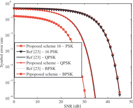
Figure 2. Comparisons of SER performances as a function of SNR.
From Eq. (24), χrect(˜τ , v) can be written as
χrect(˜τ , v) Δt
0
s(t)s(t+ ˜τ) exp (j2πv)dt (25)
= Δt− |τ˜|
Δt sinc(v(Δt− |τ˜|)) exp (jπv(˜τ+ Δt)) (26)
where|τ˜|<Δt.
6. SIMULATIONS AND RESULTS
In this section, we illustrate the results of several numerical examples to show the performance features of our proposed scheme. To be fair in our comparison, we adopt the parameters that are the same as [23], unless otherwise stated. The subchirp rate is kr = 273.
6.1. Example 1: Symbol Error Rate (SER) Performance
We evaluate the SER performance of the proposed scheme by using BPSK, QPSK, and 16-PSK constellations. The definition of SER is similar to [25], which is
P(error)≤
1
N
N−1
k=0
1−erf c
√
2SN Rsinηk/2
N
(27)
The possible values for ηk is obtained as ηk=k(2πdnsinθcom) for n= 1, . . . ,(N −1).
Figure 2 shows comparison of SER performances as a function of SNR. It can be noticed that the curves agree with the standard behavior of SER communications system. It is obvious that the symbol error rate (SER) of the proposed scheme is the same as that of [23] when BPSK, QPSK and 16 PSK constellation sizes are considered, respectively. It should be noted that the 16 PSK yields better PAPR performance. Therefore, we recommend PSK-based frequency-hopping chirp waveform for dual-function radar-communications system. The achievable corresponding data ratesDrate are as follows: BPSK = 32 Mbps, QPSK = 64 Mbps and 16-PSK = 128 Mbps.
6.2. Example 2: Waveform Comparisons
0 0.2 0.4 0.6 0.8 1 -2
-1.5 -1 -0.5 0 0.5 1 1.5
Fast Time [sec]
Real part of waveform
0 0.2 0.4 0.6 0.8 1
-1 -0.5 0 0.5 1 1.5 2
Fast Time [sec]
Real part of waveform
(a) (b)
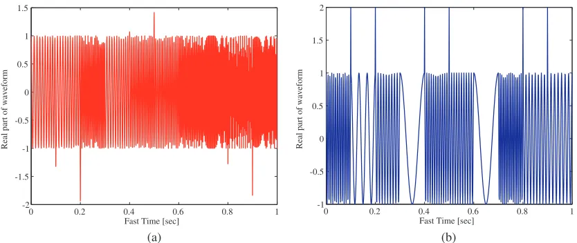
Figure 3. Plot of (a) frequency-hopping chirp waveform, (b) conventional frequency-hopping waveform.
Figure 3 compares the real part of the proposed frequency-hopping chirp waveforms with the conventional frequency-hopping waveforms used in [23, 37]. It can be seen that our proposed waveform have good peak-average ratio performance and almost constant modulus, which are desired for the RF hardware transmitter. This is rather different from the conventional frequency-hopping waveforms performance. It can also be observed that the proposed waveform has uniform spectra across the bandwidth like conventional chirp signal, and the bandwidth is covered with no visible gaps. It can be concluded that the proposed waveform can be designed to achieve a large time-bandwidth product with good peak-average ratio performance. Note that we generate multiple but dissimilar signals of the proposed waveforms.
6.3. Example 3: MIMO Radar Ambiguity Analysis on Time Delay and Doppler Frequency
In this section, we plot the MIMO radar ambiguity function of the proposed waveform and the conventional frequency-hopping waveform. Fig. 4 shows the time delay ˜τ of the proposed waveform and that of the conventional frequency-hopping waveform, respectively. It is clear from the figure that our proposed frequency-hopping chirp waveform achieves narrower mainlobe than the conventional frequency-hopping waveform. In contrast, it is apparent that our proposed waveform achieves lower sidelobe levels than that of the conventional frequency-hopping waveform.
(a) (b)
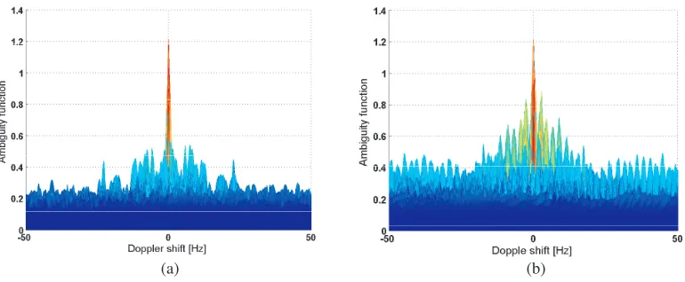
(a) (b)
Figure 5. Comparisons of MIMO radar ambiguity as a function of Doppler shift: (a) proposed waveform, (b) conventional frequency-hopping waveform.
-200 -15 -10 -5 -0
0.1 0.2 0.3 0.4 0.5 0.6 0.7 0.8 0.9 1
Magnitude [dB]
ECDF [%]
Conv. frequency hopping waveform Proposed waveform
Figure 6. Comparisons of ECDF performance results.
Figure 5 illustrates the Doppler shift performances of the proposed waveform and the conventional frequency-hopping waveform, respectively. It can be observed from the figure that our proposed waveform again achieves lower sidelobes than that of the conventional frequency-hopping waveform, and it is not sensitive to the Doppler shift because of the chirp signals adopted. Therefore, our proposed waveform is more suitable for MIMO radar applications.
Finally, we use empirical cumulative distribution function (ECDF) to evaluate the waveform ambiguity function. Fig. 6 depicts a result of ECDF. The results of the proposed waveform and that of the conventional frequency-hopping waveform are compared in the figure. It can be noticed that the proposed frequency-hopping chirp waveform yields fewer undesired peaks than the conventional frequency-hopping waveform.
7. CONCLUSION
that the communication operation does not affect the MIMO radar sensing performance. And the proposed scheme can achieve a data rate of several Mbps. Numerical results show that our proposed scheme achieves the same SER curves performance as that of [23]. Furthermore, the designed waveform has lower sidelobe levels for both time delay and Doppler shift dimensions, and better PAPR performance than the existing frequency-hopping waveform used in [23].
REFERENCES
1. Griffiths, H., S. Blunt, L. Chen, and L. Savy, “Challenge problems in spectrum engineering and waveform diversity,” Proc. IEEE Radar Conf., 1–5, Ottawa, Canada, Apr.–May 2013.
2. Baylis, C., M. Fellows, L. Cohen, and R. J. Marks, “Solving the spectrum crisis: Intelligent, reconfigurable microwave transmitter amplifiers for cognitive radar,” IEEE Microwave Magazine, Vol. 15, No. 5, 94–107, Jul.–Aug. 2014.
3. Griffiths, H., L. Cohen, S. Watts, E. Mokole, C. Baker, M. Wicks, and S. Blunt, “Radar spectrum engineering and management: Technical and regulatory issues,” Proc. IEEE, Vol. 103, No. 1, 85– 102, Jan. 2015.
4. Paisana, F., N. Marchetti, and L. A. DaSilva, “Radar, TV and cellular bands: Which spectrum access techniques for which bands?,”IEEE Commun. Surveys and Tutorials, Vol. 16, No. 3, 1193– 1220, Third Quarter, 2014.
5. Deng, H. and B. Himed, “Interference mitigation processing for spectrum-sharing between radar and wireless communications systems,” IEEE Trans. Aerospace and Electronic Systems, Vol. 49, No. 3, 1911–1919, Jul. 2013.
6. Bliss, D. W., “Cooperative radar and communications signaling: The estimation and information theory odd couple,”Proc. IEEE Radar Conf., 50–55, Cincinnati, OH, May 2014.
7. Geng, Z., H. Deng, and B. Himed, “Adaptive radar beamforming for interference mitigation in radar-wireless spectrum sharing,”IEEE Signal Process. Lett., Vol. 22, No. 4, 484–488, Apr. 2015. 8. Hayvaci, H. T. and B. Tavli, “Spectrum sharing in radar and wireless communication systems: A
review,”Proc. Int. Conf. Electromagnetics in Advanced Applications, 810–813, Palm Beach, Aruba, Aug. 2014.
9. Guerci, J. R., R. M. Guerci, A. Lackpour, and D. Moskowitz, “Joint design and operation of shared spectrum access for radar and communications,” Proc. IEEE Int. Radar Conf., 0761–0766, Arlington, VA, May 2015.
10. Khawar, A., A. Abdelhadi, and C. Clancy, “Target detection performance of spectrum sharing MIMO radars,”IEEE Sensors Journal, Vol. 15, No. 9, 4928–4940, Sep. 2015.
11. Wang, L., J. McGeehan, C. Williams, and A. Doufexi, “Application of cooperative sensing in radar-communications coexistence,”IET Communications, Vol. 2, No. 6, 856–868, Jul. 2008. 12. Huang, K. W., M. Bica, U. Mitra, and V. Koivunen, “Radar waveform design in spectrum sharing
environment: Coexistence and cognition,” Proc. IEEE Radar Conf., 1698–1703, Arlington, VA, May 2015.
13. Surender, S. C., R. M. Narayanan, and C. R. Das, “Performance analysis of communications and radar coexistence in a covert UWB OSA system,”Proc. IEEE Global Commun. Conf., 1–5, Miami, FL, Dec. 2010.
14. Sit, Y. L., C. Sturm, L. Reichardt, T. Zwick, and W. Wiesbeck, “The OFDM joint radar-communication system: An overview,”Proc. Int. Conf. Advances in Satellite and Space Commun., 69–74, Budapest, Hungary, Apr. 2011.
15. Blunt, S. D., M. R. Cook, and J. Stiles, “Embedding information into radar emissions via waveform implementation,” Proc. Int. Waveform Diversity and Design Conf., 8–13, Niagara Falls, Canada, Aug. 2010.
17. Hassanien, A., M. G. Amin, Y. D. Zhang, and F. Ahmad, “Dual function radar-communications using phase-rotational invariance,” Proc. European Signal Processing Conf., 1346–1350, Nice, France, Aug.–Sep. 2015.
18. Hassanien, A., M. G. Amin, Y. D. Zhang, and F. Ahmad, “Dual-function radar-communications: Information embedding using sidelobe control and waveform diversity,” IEEE Trans. Signal Processing, Vol. 64, No. 8, 2168–2181, Apr. 2016.
19. Hassanien, A., M. G. Amin, Y. D. Zhang, and F. Ahmad, “Efficient sidelobe ASK based Dual-Function radar-communications,” SPIE Defense and Security, Radar Sensor Technology Conf., Baltimore, MD, Apr. 2016.
20. Hassanien, A., M. G. Amin, and Y. D. Zhang, “Computationally efficient beampattern synthesis for dual-function radar-communications,” SPIE Defense and Security, Radar Sensor Technology Conf., Baltimore, MD, Apr. 2016.
21. Hassanien, A., M. G. Amin, Y. D. Zhang, and F. Ahmad, “Signaling strategies for dual-function radar-communications: An overview,”IEEE Aerospace and Electronic Systems Magazine, Vol. 31, No. 10, 36–45, Oct. 2016.
22. Hassanien, A., M. G. Amin, Y. D. Zhang, and F. Ahmad, “Phase modulation based dual-function radar-communications,” IET Radar, Sonar and Navigations, Vol. 10, No. 8, 1411–1421, Oct. 2016. 23. Hassanien, A., B. Himed, and B. D. Rigling, “A dual-function MIMO radar-communications system
using frequency-hopping waveforms,” Proc. IEEE Radar Conf., 1721–1725, May 8–12, 2017. 24. Hassanien, A., M. G. Amin, Y. Zhang, and B. Himed, “A dual-function MIMO
radar-communications system using PSK modulation,” Proc. of the European Signal Processing Conf.,
(EUSIPCO), Budapest, Hungary, Aug. 2016.
25. BouDaher, E., A. Hassanien, E. Aboutanios, and M. G. Amin, “Towards a dual-function MIMO radar-communication system,” Proc. IEEE Radar Conf., Philadelphia, PA, May 2016.
26. Wang, W. Q., “MIMO SAR OFDM chirp waveform diversity design with random matrix modulation,” IEEE Trans. on Geoscience and Remote Sensing, Vol. 53, No. 3, 1615–1625, Mar. 2015.
27. Friedlander, B., “On the relationship between MIMO and SIMO radars,” IEEE Trans. on Signal Processing, Vol. 57, No. 1, 394–398, Jan. 2009.
28. Welstead, S., “Characterization of diversity approaches for LFM stretchprocessed waveforms,”
Proceedings of the International Waveform Diversity and Design Conf., 418–422, Pisa, Jun. 2007. 29. Kim, J. H., M. Younis, A. Moreira, and W. Wiesbeck. “A novel OFDM chirp waveform scheme for use of multiple transmitters in SAR,” IEEE Geoscience and Remote Sensing Letters, Vol. 10, No. 3, 568–572, May 2013.
30. Wang, W. Q., “MIMO SAR chirp modulation diversity waveform design,” IEEE Geoscience and Remote Sensing Letters, Vol. 11, No. 9, 1644–1648, Sep. 2014.
31. Skolnik, M. I.,Introduction to Radar Systems, 3rd Edition, McGraw-Hill, New York, NY, 2001. 32. Song, X., S. Zhou, and P. Willett, “Reducing the waveform cross correlation of MIMO radar with
spacetime coding,” IEEE Trans. on Signal Processing, Vol. 58, No. 8, 4213–4224, Aug. 2010. 33. Patton, L., C. Bryant, and B. Himed, “Radar-centric design of waveforms with disjoint spectral
support,”Proc. IEEE Radar Conf., 1106–1110, May 2012.
34. Aubry, A., A. De Maio, M. Piezzo, and A. Farina, “Radar waveform design in a spectrally crowded environment via nonconvex quadratic optimization,” IEEE Trans. Aerospace and Electronic Systems, Vol. 50, No. 2, 1138–1152, Apr. 2014.
35. Patton, L. K. and B. D. Rigling, “Modulus constraints in adaptive radar waveform design,”Proc. IEEE Radar Conf., 1–6, Rome, May 2008.
36. Han, K. and A. Nehorai, “Jointly optimal design for MIMO radar frequency-hopping waveforms using game theory,” IEEE Trans. Aerospace and Electronic Systems, Vol. 52, No. 2, 809–820, Apr. 2016.
38. Levanon, N. and E. Mozeson,Radar Signals, Wiley-IEEE Press, New York, NY, USA, 2004. 39. San Antonio, G., D. R. Fuhrmann, and F. C. Robey, “MIMO radar ambiguity functions,” IEEE
Journal of Selected Topics on Signal Processing, Vol. 1, No. 1, 167–177, Jun. 2007.