High Resolution MIMO-HFSWR Radar Using Sparse
Frequency Waveforms
Guohua WANG, Yilong LU
School of Electrical and Electronic Engineering, Nanyang Technological University, Singapore E-mail:{wang0330, eylu}@ ntu.edu.sg
ReceivedApril 21, 2009; revised May 12, 2009; accepted May 15, 2009
Abstract
In high frequency surface wave radar (HFSWR) applications, range and azimuth resolutions are usually lim-ited by the bandwidth of waveforms and the physical dimension of the radar aperture, respectively. In this paper, we propose a concept of multiple-input multiple-output (MIMO) HFSWR system with widely sepa-rated antennas transmitting and receiving sparse frequency waveforms. The proposed system can overcome the conventional limitation on resolutions and obtain high resolution capability through this new configura-tion. Ambiguity function (AF) is derived in detail to evaluate the basic resolution performance of this pro-posed system. The advantages of the system of fine resolution and low peak sidelobe level (PSL) are demon-strated by the AF analysis through numerical simulations. The impacts of Doppler effect and the geometry configuration are also studied.
Keywords:MIMO, HFSWR, Radar, Sparse Frequency Waveform
1. Introduction
HIGH frequency surface wave radar (HFSWR) is a low-cost radar system that adopts vertically polarized high frequency electromagnetic signals which propagate along the ocean surface. A preferable property of HFSWR is that it can detect and track ship and aircraft targets beyond the horizon. Due to this reason, HFSWR has a wide range of applications in both civil and mili-tary fields. For conventional HFSWR systems, its range resolution is highly restricted by the bandwidth of avail-able clear channels in a congested spectrum environment [1,2], while the azimuth resolution is also constrained by the physical dimension of the radar antenna aperture.
Multiple-input multiple-output (MIMO) radar is now getting much intention for various applications such as detection, estimation, and imaging etc. MIMO radar can transmit at transmitters multiple waveforms that are di-vidual at the receivers so that it can obtain more degrees of freedom compared with conventional radars that transmit single waveform [3–6]. With widely distributed antennas, angular diversity can be fully achieved to compete with the target scintillations [7,8]. Meanwhile, MIMO radars with widely distributed antennas can gain high resolution by coherent processing [8]. Like
distrib-uted MIMO radar, a single-input multiple-output (SIMO) radar system with sparse coherent receiving aperture can also achieve high resolution on the order of one wave-length with limited bandwidth as reported in [9].
153
frequency waveform it not only takes more clear chan-nels into use to compete with co-channel interference but also reduces the peak sidelobe level (PSL).
The reminder of this paper is organized as follows. The AF of the proposed MIMO-HFSWR using sparse frequency waveforms is derived in Section 2. Based on AF analysis and simulations the system is evaluated in terms of resolution capacity and PSL performance, with zero Doppler frequency in Section 3 and under the fac-tors of geometric configurations and Doppler effects in Section 4. Finally, conclusions and future work are out-lined in Section 5.
2. Ambiguity Function of MIMO-HFSWR
System Using Sparse Frequency
Waveforms
Ambiguity function is an important tool in conventional radar analysis as it shows radar’s inherent capacity of discriminating targets associated with different time de-lay and Doppler frequency. Thus, in this paper, we also employ AF to evaluate the performance of the proposed system.
The proposed MIMO-HFSWR system consists of M
transmitters transmitting M waveforms and N receivers. Each transmitter is assigned a distinct channel with starting frequency fm,m=1, 2,…, M. Thus, collectively, the transmitting waveforms will have a sparse spectrum, because which we call the transmitting waveforms sparse frequency waveform. All antennas are arbitrarily located with mutual separation distance larger than several wavelengths in a 3-dimensional space. Figure 1 shows the system configuration, where Rn and Tm refer to the
n-th receiver and the m-th transmitter, respectively. Each transmitter and each receiver are located at a point represented by a 3-dimensional vector in the Cartesian coordinate system. For example, the m-th transmitter is associated with a vector ct,m=[xm, ym, zm], and the n-th receiver cr,n=[xn, yn, zn]. For simplification, this paper considers only single point target case. And the target is assumed to be located at a general point x = [x, y, z] with constant velocity of v = [vx, vy, vz]. As the antennas are widely distributed, each of them will view the target with
m
[image:2.595.313.541.523.726.2]m
Figure 1. MIMO radar configuration.
a different angle. Angle variables θ and φ refer to the true elevation and azimuth as illustrated in Figure 1. We also assume that the phases and time at the transmitters and receivers are synchronized in advance. Meanwhile, the signal attenuation in different path is assumed to be the same.
Let xm(t) be the signal transmitted by the m-th trans-mitter that meets the requirement of narrow band as-sumption. It is expressed as
exp( 2 )
m m m
x t j f t s t
(1)
where sm(t) is the baseband waveform of the m-th trans-mitter. After the signal impinged back from the target to the n-th receiver, the echo is:
( ) M
n m nm nm
m=1
e t =
x t- exp -j2πfd t (2)where γ is the complex reflection coefficient of the target,
τnm is the round-trip delay, and fdnm is the Doppler fre-quency of the echo at the n-th receiver due to the m-th
transmitter. We take the assumption that the target stops during the pulse transmission and reception. Then τnm is the round-trip delay at the start of observation time, and has the form
0 2 2 2 2 / / / / m nnm T R t
m m m
n n n
r t c r t c
x x y y z z
x x y y z z c
c (3)
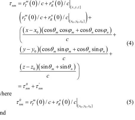
where c is the velocity of light in the media that the transmitters, receivers and targets are located in. In the case that the transmitters or the receivers are mounted on moving platform, the platform velocity can also be easily included in (3). For different scatter, τnm is a function of variables x, y, and z. Thus, through Taylor-series analysis at a reference point x0=[x0, y0, z0], (3) can be changed to
0 0 0
[ , , ]
[ , , ]
0
0
0
0 / 0 /
0 / 0 /
cos cos cos cos
cos sin cos sin
sin sin
m n
nm T R x y z
m n
T R x y z
m m n n
m m n n
m n
0 '
nm nm
r c r c
r c r c
x x c y y c z z c (4) where
0 0 0
[ , , ]
0 / 0 /
0 m n
nm rT c rR c x y z
0 0 0cos cos cos cos
cos sin cos sin
sin sin
m m n n
' nm
m m n n
m n x x c y y c z z c (6)
fdnm has the form
1 m n
nm T R
m
d
fd r t r
dt
t (7)
Again, through Taylor-series analysis (7) can be changed to
02 2 2 2 2
cos sin cos sin
cos cos cos cos
sin sin
2
x m y m z m x n y n z n
dnm
m m m m m n n n
y m m n n
x m m n n
m m
z m n
m
v x x v y y v z z v x x v y y v z z
f
x x y y z z x x y y z z
v v v (8)
It can be easily proved that (8) is a tantamount expres-sion of conventional Doppler frequency of bistatic radar.
As each transmitting waveform is assigned to a dis-tinct channel, orthogonality holds for all the transmitting signals. Thus, at each receiver, signals from M
transmit-ters can be firstly separated by down-converting into M
channels. Then, for each channel, a matched filter of corresponding transmitting waveform is employed at the interested range cell centered at x0= [x0, y0, z0]. Thus, the
m-th filter output at the n-th receiver can be expressed as
0
0 0 *
' '
, ,
exp 2 exp 2
exp 2 ,
nm nm
nm nm
nm
m nm m nm m nm nm
m mm nm nm
y
= j f s t j fd t s t dt n
= j f fd +n t
x x vA
t
(9)
where Amm is the correlation between the m-th transmit-ting waveform and its delay-Doppler shifted version, and
nnm (t) is the noise component of the output.
Collectively, there are NM outputs after matched fil-tering.By coherently summing all these outputs we can get:
0
0 21 1
, , N M n m , ,
n m
y
A x x v x x v (10)
Besides, different waveforms may obtain different
Amm, thus waveforms also play a key role in the MIMO radar ambiguity function. We take Linear Frequency Modulation (LFM) waveforms as an example to illustrate this point. A conventional LFM waveform defined by
u(t)=rect(t/T)exp(jπkt2) has an correlation function like [12]:
2
A ,vLFM exp j k 1 sinc vT B 1
T T
Because both τ’nm and fdnm in (9) are affected by azi-muth angles and elevation angels, the geometry configu-ration represented by a matrix C consisting of all the azimuth and elevation angels should be included in the ambiguity function. Ignoring the noise-based component and discarding the target reflection coefficient in (10), we can define the normalized ambiguity function for the proposed system as:
(12) where v is the Doppler frequency, τ is the time-delay, k is the chirp rate, T is the pulse width, B is the bandwidth. From (12), it can be easily inferred that the bandwidth of single waveform adopted will impact the performance of the MIMO-HFSWR system.
3. Resolution Capacity and PSL
0 2 2
2 ' ' 1 1 1 , , , , nm nm N M
m mm nm
n m
M N
exp -j2πf f
x x v CA
Performance
d (11) In this section, the resolution capacity and PSL of the MIMO-HFSWR system using sparse frequency wave-form are assessed by setting the Doppler frequency to zero in AF analysis. Sparse frequency waveforms con-sisting of stepped frequency linear frequency modulation signals are investigated. For simplification we just study a simplified 2-dimensional configuration.
As τ’nm and fdnm arerelated to x−x0, y−y0, z−z0, vx, vy,
155
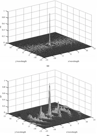
(a)
[image:4.595.112.488.82.610.2](b)
Figure 2. MIMO AF of (a) Sparse frequency waveforms (b) Single LFM signal, at zero Doppler frequency.
As we can see from above analysis, the ambiguity function of the proposed MIMO-HFSWR system de-pends on the system geometry configuration confined by all azimuth and elevation angles. Thus, we can ignore the true position of transmitters and receivers. We here take nine transmitters and nine receivers located evenly over
by sequentially transmitting at transmitters or by setting the first five LFM waveforms to be up-chirps and the left four down-chirps [12]. We in this paper utilize the first mechanism. As a comparison, we also take an ambiguity function from a single LFM waveform with the same bandwidth and pulse width as well as the start frequency of 9 MHz. We also suppose to transmit it sequentially in time domain so that we can separate at each receiver the
returns from different transmitters. By central coherent processing we can also get the results of AF as showed in Figure 2(b), which seems the same as that in [8].
The mesh plots of the AF are showed in Figure 2 and more details on resolutions and sidelobe characteristics are given in Figure 3 and Table 1. As is obvious from both Figure 3 and Table 1, the resolutions of MIMO- HFSWR are at the level of one wavelength for both
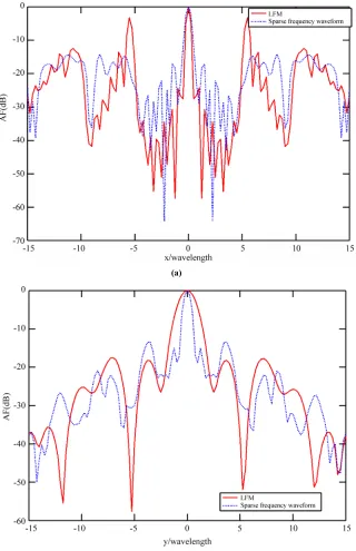
(a)
[image:5.595.139.459.188.683.2](b)
157
Table 1.Resolution and sidelobe characters of different waveforms.
Item Sparse frequency waveforms LFM
Resolution of x 0.31 wavelength 0.58 wavelength
PSL-x –14.9 dB –3.2 dB
Resolution of y 0.9 wavelength 1.6 wavelength
PSL-y –13.5 dB –16.5 dB
(a)
(b)
sparse frequency waveforms and single LFM waveform. And the resolutions of sparse frequency waveforms are even better than those of common LFM signals. This is a great improvement for azimuth resolution and even for range resolution from conventional several kilometers to several tens meters. Meanwhile, as HFSWR always works in a highly congested spectrum environment, the sparse frequency waveform approach can provide better flexibility on choosing available channels than
wave-forms confined in only one channel. The sidelobes of x-axis and y-axis are well below –13 and –14 dB for sparse frequency waveforms, respectively, which is a significant improvement compared with the side lobe level from the single LFM waveform within the same channel. It demonstrates that the sidelobe levels can be suppressed by frequency diversity in random arrays [13]. This is another advantage of sparse frequency waveform.
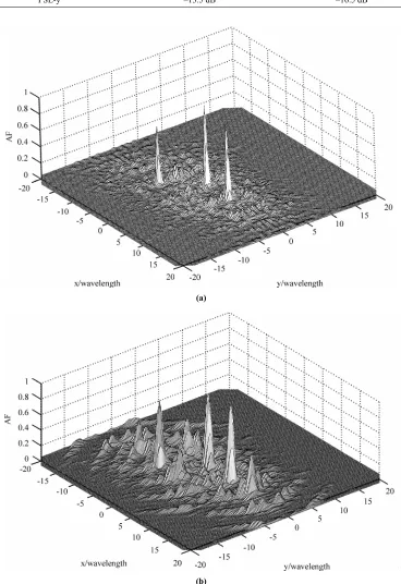
Multiple targets case are illustrated in Figure 4, where
(a)
[image:7.595.128.464.197.694.2](b)
159
(a)
[image:8.595.111.484.74.613.2](b)
Figure 6. Ambiguity functions of (a) Configuration 1 and (b) Configuration 2 in case 1 with velocity [vx, vy] = [500, 500] m/s.
Configuration 1 (9×9), Configuration 2 (5×5), both evenly distributed in (−π/4, π/4).
three targets are located in [0, 0], [0, 10], and [–10, –10]. The coordinate system is expressed in multiples of wavelength. As we can see, by using sparse frequency waveform set, the system can better distinguish different targets than by using waveform set in the same channel.
(a)
[image:9.595.115.480.76.612.2](b)
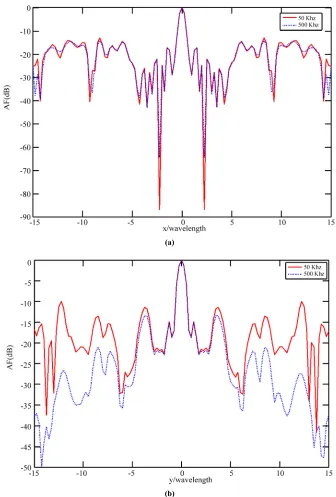
Figure 7. Resolution and sidelobe performance along (a) x-axis and (b) y-axis in case 1 with velocity [vx, vy] = [500, 500] m/s.
Configuration 1 (9×9), Configuration 2 (5×5), both evenly distributed in (−π/4, π/4).
However, the PSL performance is deteriorated. The PSL in x-axis is about –12.9 dB and is about –10 dB in y-axis for this waveform set. Thus, we can see that the larger the bandwidth adopted, the lower the sidelobes in both
x-axis and y-axis.
161
Further work will be focused on the suppression of sidelobe levels by waveforms with effective frequency diversity scheme.
4. Doppler and Geometry Factor
As HFSWR is always operated in Doppler circumstances, the AF with Doppler effects should be further investi-gated. Meanwhile, unlike monostatic radar the distrib-uted MIMO radar is confined by the geometry configura-tion. Thus the geometry factor should also be investi-gated. Two cases are given below to investigate the Doppler and configuration effect.
In Case 1, we study the configuration effect. Target of this case is with velocity of [vx, vy] = [500, 500] m/s. This is a high velocity target case corresponding to air targets. There are two configurations. For Configuration 1, in the region of (–π/4, π/4) there are nine transmitters and nine receivers, evenly distributed. The transmitting wave-forms are defined as those in Section 3 except that each one has 10 kHz bandwidth. For practical HFSWR appli-cation, only a limited number of continuous clear chan-nels with bandwidth of a few kilo-Herz in the 3-30 MHz high frequency band can be found and used at a time when interference is considered [1,2]. Thus, 10 kHz bandwidth is used for a much more similitude in real condition of the HFSWR system. For Configuration 2, in
the same region of (–π/4, π/4) there are five transmitters and five receivers, evenly distributed. The waveforms are the first five used in Configuration 1 of Case 1. Thus, the total spectra employed by these two configurations are the same. As illustrated in Figure 6, Figure 7, both con-figurations in this case show high resolution capabilities. However, Configuration 1 with more transmit-receive pairs shows better sidelobe performance in both x-axis and y-axis. The PSL in x-axis is about –12 dB and is about –10.5 dB in y-axis for Configuration 1. Based on our numerous simulation experiments, it is found that as more pairs of transmitter and receiver are set in a much wider spatial region, the resolutions can be slightly im-proved and the PSLs of y-axis and x-axis can be further reduced. However, systematic study on the PSLs reduc-tion through geometry optimizareduc-tion will be explored in the future.
In Case 2: we have four velocity settings like [0, 0] m/s, [100, –100] m/s, [–10, 5] m/s, and [500, 500] m/s. The geometry configuration in Case 2 is the same as Configuration 1 in Case 1. We also take the waveform set of Configuration 1of Case 1 in this case study. Figure 8 shows the results of Case 2. We can see from Figure 8 that the proposed system shows similar characteristics in different Doppler context, which means the resolution and PSL performance are both insensitive to Doppler frequency. Thus, for both high speed air targets and low
(a) v=[0,0] m/s (b) v=[100, −100] m/s
[image:10.595.108.488.414.701.2](c) v=[−10,5] m/s (d) v=[500,500] m/s
velocity surface targets, the proposed system can also have high resolution performance.
5. Conclusions
In this paper, the concept of distributed MIMO-HFSWR radar transmitting sparse frequency waveforms is pro-posed. The AF of this proposed system is derived in de-tail. Potential advantages of the proposed system on resolution capacity and PSL performance are assessed through AF analysis and simulations. The impacts of Doppler effects and the geometry configuration factor are also studied. It has been found that the system has several distinguished characteristics. Firstly, the range resolution and the azimuth resolution can be improved to the level of one wavelength, namely, only tens meters and the PSL is reduced to a much lower level with sparse frequency waveforms. Meanwhile, the resolutions are not restricted by individual bandwidth while the PSL can benefit from large bandwidth. Secondly, the performance of fine resolution and low PSL are insensitive to the Doppler effects. Thus, for both high speed air and low velocity surface targets, the proposed system also has high performance. Thirdly, the resolution capacity and PSL performance can be optimized through geometry configuration optimization. In addition, multistatic con-figuration provides large flexibility to find a proper place to locate the radar transmitters and receivers; by using sparse frequency waveforms, it is much easier to find more available channels in different locations thus the co-channel interference can be avoided and the perform-ance can be further improved. Further studies will be conducted on the surveillance strategy and high quality waveforms with better AF performance. Meanwhile, synchronization problem should also be paid special at-tention to so that coherent processing can be conducted perfectly.
6. References
[1] H. W. H. Leong and B. Dawe, “Channel availability for east coast high frequency surface wave radar systems,” Defence R&D Canada, Technical Report, DREO TR 2001-104, November 2001.
[2] R. J. Riddolls, “A Canadian perspective on high fre-quency over-the-horizon radar,” Defence R&D Canada, Technical Report, DREO TR 2006-285, December 2006. [3] D. W. Bliss and K. W. Forsythe, “Multiple-input multi-ple-output (MIMO) radar and imaging: Degrees of free-dom and resolution,” Proceedings of the 37th Asilomar Conference on Signal, Systems and Computers, pp. 54–59, November 2003.
[4] J. Li, “MIMO radar: Diversity means superiority,” Pro-ceedings of the 14th Annual Adaptive Sensor Array Proc-essing Workshop-2006, June 6–7, 2006.
[5] S. Peter, J. Li, and Y. Xie, “On probing single design for MIMO radar,” IEEE Transactions on Signal Processing, Vol. 55, No. 8, pp. 4151–4161, August 2007.
[6] G. San Antonio, D. R. Fuhrmann, and F. C. Robey, “MIMO radar ambiguity function,” in IEEE Journal of Selected Topics in Signal Processing, Vol. 1, No. 1, pp. 167–177, June 2007.
[7] E. Fisher, A. Haimovich, R. Blum, L. Cimini, D. Chizhik, and R. Valenzuela, “Spatial diversity in radars—models and detection performance,” IEEE Transactions on Signal Processing, Vol. 20, No. 3, pp. 823–838, March 2006. [8] N. H. Lehmann, A. M. Haimovich, R. S. Blum, and L.
Cimini, “High resolution capabilities of MIMO radar,” Proceedings of the 40th Asilomar Conference on Signal, Systems and Computers,pp. 25–30, November 2006. [9] D. R. Kirk,J. S. Bergin, P. M. Techau, and J. E. Don
Carlos, “Multi-static coherent sparse aperture approach to precision target detection and estimation,” Proceedings of 2005 IEEE Radar Conference, pp. 579–584, May 2005. [10] G. H. Wang, W. X. Liu, and Y. L. Lu, “Sparse frequency
transmit waveform design with soft power constraint by using PSO algorithm,” Proceedings of 2008 IEEE Radar Conference, pp. 1–6, May 2008.
[11] W. X. Liu, Y. L. Lu, and M. Leisturgie, “Optimal sparse waveform design for HFSWR system,” Proceedings of 2007 International Waveform Diversity and Design Con-ference, pp. 127–130, May 2007.
[12] N. Levanon and E. Mosezen, Radar Signals, John Wiely & Sons, New Jersy, 2004.
![Figure 6. Ambiguity functions of (a) Configuration 1 and (b) Configuration 2 in case 1 with velocity [vx, vy] = [500, 500] m/s](https://thumb-us.123doks.com/thumbv2/123dok_us/8741469.388267/8.595.111.484.74.613/figure-ambiguity-functions-configuration-configuration-case-velocity-vx.webp)
![Figure 7. Resolution and sidelobe performance along (a) x-axis and (b) y-axis in case 1 with velocity [vConfiguration 1 (9×9), Configuration 2 (5×5), both evenly distributed in (x, vy] = [500, 500] m/s](https://thumb-us.123doks.com/thumbv2/123dok_us/8741469.388267/9.595.115.480.76.612/figure-resolution-sidelobe-performance-velocity-vconfiguration-configuration-distributed.webp)

