Practical Multiuser Detection
Algorithms for CDMA
A thesis for the fulfilment of the
the Degree of Master of Engineering
By Kevin Anderson
l§ LlBRARY
A n investigation carried out within
School of Communications and Informatics
Faculty of Engineering and Science
Victoria University of Technology
Dedication
This thesis and work in Multiuser Detection is dedicated to m y Lord and Saviour, our Lord Jesus Christ.
"Fear of the Lord is the beginning of knowledge. Only fools
despise wisdom and discipline " Prov. 1:7
"Choose Instruction rather than silver, and knowledge over pure
gold. For wisdom is far more valuable than rubies. Nothing you
desire can be compared with it" Prov 8:10-11
"And now all glory to God, who is able to keep you from stumbling,
and who will bring you into his glorious presence innocent of sin and with
great joy. All glory to him, who alone is God our Saviour, through
Jesus Christ our Lord. Yes, glory, majesty, power, and authority belong
to him, in the beginning, now, and for ever more. Amen " Jude 24-25
Declaration
M y Master studies were conducted under the guidance of Dr. Fu-Chun Zheng and Associate Professor Mike Faulkner. S o m e of the research results reported in this paper have been published as an
academic paper and presented as a conference paper.
1. K. Anderson, F.C. Zheng, M. Faulkner, "A Study on the performance of the Partial PIC C D M A detector in the presence of time offset errors" IEEE International
Symposium on Signal Processing and its Applications, ISSPA 99,pp. 709-712
Brisbane Australia.
I hereby declare that the contents of this thesis are the results of original research except where appropriately referenced, and have not been submitted for a degree at any other university or
educational institution.
}
6*H/
Kevin Anderson
School of Communications and Informatics Faculty of Engineering & Science
Acknowledgements
Research for this thesis has been carried out at the School of Communications and Informatics at Victoria University, Melbourne Australia. The work towards this thesis was initialised in February of 1998.
I wish to express my gratitude to my supervisors Dr Fu-Chung Zheng and Dr Mike Faulkner for their comments and guidance throughout m y research work and without them none of this work would have
been possible. I a m very grateful for the long hours that D r Zheng has given m e for reviewing m y thesis. The financial support, which was provide by the School of Informatics and Communications and enabled this work, is also gratefully acknowledged.
I am very thankful to my parents for the help, support and the love they have provided me throughout my life. T h e positive attitude towards education in our h o m e has been an important driving force for m y latter
Abstract
T h e aim of this thesis is to investigate practical multiuser demodulation algorithms for mobile communications systems that are based on code division multiple access ( C D M A ) technologies. These include the adaptive receiver and the interference canceller. T h e overall complexity of implementing them is examined. T h e effects of the proposed algorithms on reducing of multiple access interference ( M A I ) and their resistance to the Near Far Effect ( N F E ) will be explored.
Significant work was performed in the investigation of the effect of time offset errors on the partial parallel interference canceller (PIC). T h e performance of it is compared against that of the standard PIC.
Table of Contents
List of Abbreviations i
List of Figures iii
List of Tables v
1 Introduction 1
2 Direct Sequence Spread Spectrum Systems 4
2.1 Direct Sequence Spread Spectrum 4
2.2 Spreading Gain 5 2.3 Characteristics ofa Code Division Multiple Access System 7
2.4 Model of Asynchronous C D M A System 8
2.5 Transmitter Model 9 2.6 Channel Model 10 2.7 Processing the received signal 10
2.7.1 Continuous Time Model 11 2.7.2 Discrete Time Model 13 2.8 Performance Analysis of the Single User Receiver 15
2.8.1 Conventional Single User Receiver 16 2.8.2 Simulation ofa C D M A system with Near Far Effect 18
3 Multiuser Detection: an Overview 20
3,1 Conventional Receiver 20 3.2 Linear Multiuser Detectors 21
3.5 Interference Cancellation 25 3.5.1 Successive Interference Cancellation 25
3.5.2 Parallel Interference Cancellation 26
4 Multiuser Detection: an in-depth analysis 29
4.1 O p t i m u m receiver 30 4.2 Sub-Optimum Detectors 32 4.3 T h e Decorrelating Detector 33 4.4 M i n i m u m M e a n Squared Error ( M M S E ) Detector 34
5 Adaptive Linear Receivers 38
5.1 Adaptive Filters 38 5.2 Adaptive Linear Receiver 45
5.2.1 Method of Operation 46 5.2.2 T h e L M S update algorithm for the Adaptive Receiver 49
5.2.3 Convergence properties of the Adaptive Receiver 49
5.3 Adaptive Receiver Structures 50 5.3.1 Single user detection 50 5.3.2 Multiuser detection 51 5.4 Adaptive Linear Receiver performance analysis and results 52
5.4.1 Convergence of the Adaptive Receiver 52 5.4.2 Performance of Adaptive Recevier in Near Far Environment 56
6 Interference Cancellation 58
6.1 Parallel Interference Cancellation 59 6.1.1 A model of the PIC receiver 60 6.2 Partial Parallel Interference Cancellation using Soft Detection 62
6.2.1 Synchronisation Errors in the partial PIC 65 6.2.2 Performance of the Partial PIC in presence of time offset errors 67
6.3 Channel Estimation 71 6.4 Serial Interference Cancellation 72
8 References
Appendix A : Published Paper.
List of Abbreviations
A/D
A W G N
B-ISDN
BER
BPSK
C D M A
DS-CDMA
DS-SS
FDMA
FIR
GFC
HD
IC
ISI
LMMSE
LMS
MAI
MATLAB
MF
MLSD
M U D
NBI
NFE
PIC
PN
SD
SIC
Analogue to Digital Converter Additive White Gaussian Noise
Broadband Integrated Services Digital Network Bit Error Rate
Binary Phase Shift Keying C o d e Division Multiple Access
Direct Sequence C o d e Division Multiple Access Direct Sequence Spread Spectrum
Frequency Division Multiple Access Finite Impulse Response
Gradient - Search Fast Converging Hard Decision
Interference Canceller Intersymbol Interference
Linear M i n i m u m M e a n Squared Error Least M e a n Square
Multiple Access Interference
Matrix Laboratory (Mathematical Programming Tool) Matched Filter
M a x i m u m Likelihood Sequence Detector Multiuser Detector
Narrowband Interference Near Far Effect
Parallel Interference Canceller Pseudo Noise
Soft Decision
SINR Signal Interference Noise Ratio S N R Signal Noise Ratio
T D M A Time Division Multiple Access
List of Figures
Figure 1. Formation of a Spread Spectrum Signal.
Figure 2 The effect of processing gain on an interfering signal. Figure 3. Model of a D S - C D M A system with K users
Figure 4. Diagram showing the signals of Users 1 ..K at the antenna input at the receiver Figure 5. Block diagram of a discrete C D M A receiver
Figure 6. Block diagram of B E R analysis
Figure 7. Theorectical B E R V s S N R for Codelengths of 63 31 15 7
Figure 8. Experimental B E R V s S N R for C D M A System with Codelengths of 63, 31, 15 and 7 Figure 9. Near Far Effect of a multiuser conventional C D M A system
Figure 10. Block diagram of Matched Filter. Figure 9. Diagram of a linear multiuser detector Figure 10. Block diagram of adaptive filter
Figure 11. Diagram showing discrete implementation of adaptive filter Figure 12. Adaptive Receiver
Figure 13. Diagram showing interference from other users symbols Figure 14. Diagram of a Single User Receiver.
Figure 15. Diagram of an Adaptive Multiuser Receiver.
Figure 15. Convergence of M S E V s Samples for an Adaptive C D M A Receiver Figure 16 Convergence of Adaptive C D M A R x with 4 users different power levels Figure 17 Convergence of 31 users, with the same power level
Figure 18. Near Far Effect of 4 users in an adaptive C D M A Receiver Figure 19 A Parallel Interference Canceller
Figure 20 A block diagram showing inter-connectivity of the PIC Figure 21 Interconnectivity of the Partial Parallel Interference Canceller Figure 22. Block diagram of the partial parallel interference canceller.
Figure 24 Asynchronous D S - C D M A system with 4 users, time offset error = 0.1 OTc, and
Eb/No = 7dB
Figure 25 Asynchronous D S - C D M A system with 4 users, time offset error = 0.20Tc, and
Eb/No= 7dB
Figure 26 Asynchronous D S - C D M A system with 4 users, time offset = 0.40 of a chip, and
Eb/No= 7dB
List of Tables
Table 1 Parameters for the conventional Matched Filter Receiver Table 2 Power Levels of the four users in the simulation of Figure
Table 3X Performance of the 4 user C D M A system for both Adaptive and Matched Filter Receivers
1 Introduction
Transmission of information has become a key feature of the modern w a y of life. T h e possibilities offered by telecommunications are changing the w a y people work, shop and spend their leisure time etc. The advancing communication and information processing technologies create more markets for n e w communication services and products. In particular, the demand for wireless communication services has increased rapidly and this trend is expected to continue. A s these technologies improve, services will demand a higher throughput of data. Wireless video and Internet services will soon be available to the consumer's mobile phone. T o cope with these changes, current wireless technologies will have to change in order to cope with both the higher transfer rate of data and as well as not causing a degradation in the overall system capacity. Current multiple access technologies include T i m e Division Multiple Access ( T D M A ) and Frequency Division Multiple Access ( F D M A ) .
With advancements in technology, wireless communications is forever changing. We are seeing new types of spectrally efficient modulation schemes, increasing emphasis on digital systems and increasing concern with spectral efficiency and user capacity.
The growth in wireless communications necessitates more efficient utilisation of the available spectrum. Increased capacity and sharing of the spectrum translates into a higher likelihood of users interfering with
Internationally the current trend in wireless communications is towards a system that can handle this increase in d e m a n d for higher capacity as well as suppressing any interference from multipath fading and other users. Wideband code division multiple access ( W - C D M A ) is such a system that the international communications community is considering for any future developments in wireless communications. It is deemed as one of the key growth areas in wireless communications.
Over the past several years, CDMA has shown to be a viable alternative to both frequency division multiple access ( F D M A ) and time division multiple access ( T D M A ) , and the use of spread spectrum techniques (upon which C D M A is based) in wireless communications applications has become a very active area of research and development. While there does not appear to be a single multiple access technique that is superior to others in all situations, there are s o m e characteristics of spread spectrum systems that give C D M A m a n y advantages.
The two basic problems which can cause interference in a radio link are multipath fading and interference from other users or systems that are operating in close proximity. Spread Spectrum signals are effective
in mitigating multipath interference and interfering signals due to the wide bandwidth and spreading gain, which introduces frequency diversity. This results in a system that has a higher capacity compared to that o f a non spread spectrum system.
One of the key factors that limits the capacity and performance of CDMA systems is Multiple Access Interference ( M A I ) . M A I is responsible for the Near-Far Effect ( N F E ) , in which strong unwanted signals completely s w a m p out the w e a k wanted signal. The N F E is only a limitation of the conventional receiver not C D M A itself. If perfect power control is used then the contribution to M A I by any one user is usually small, but as the number of users increases, the problem with M A I also becomes significantly important.
In a communications system that is based on conventional detection, the immunity against MAI depends heavily on the selection of the spreading signatures. If the chosen spreading codes or signatures are
T o reduce the impact of M A I and the Near Far Effect, a receiver could be designed to take into consideration this interference. This type of receiver would track and demodulate all of the user waveforms simultaneously; which is termed multiuser demodulation. T h e multiuser receiver makes a decision based on the observation of the whole received waveforms for all users.
This thesis comprises eight chapters. Chapter 1 is an introduction to spread spectrum communications from a systems point of view and presents w h y multiuser receivers are necessary for a C D M A system. Chapter 2 investigates mathematical models for a direct sequence code division multiple access system ( D S - C D M A ) , it details h o w the simulations were setup and presents the results for the conventional
2 Direct Sequence Spread Spectrum Systems
This chapter starts off by looking at a h o w a direct sequence spread spectrum (DS-SS) signal is formed. It then describes the advantages of spreading gain and processing gain and investigates mathematical models for adirect sequence code division multiple access ( D S - C D M A ) system. T h e chapter is concluded with the results for the conventional matched filter receiver.
2.1 Direct Sequence Spread Spectrum
T h e usage ofa spread spectrum system implies that the signals spectrum has been expanded and its signal energy has been distributed over a m u c h larger bandwidth. If the signal suffers from frequency selective fading in the channel, only a small portion of the original signal will suffer some degradation. This is due to that it is very unlikely that all frequencies within the widened signal bandwidth will be faded.
In the transmitter, the spreading sequence or signature multiplies the original narrowband signal to cause
a spectral spreading of the original narrowband signal. This signature comprises ofa pusedo-noise like
In the receiver the (complex-conjugated) spreading sequence again multiplies the received signal to
collapse the spectrum. If the reference signature of the receiver is synchronised to the data modulated P N
sequence in the received signal, the original signal can be recovered. A brief overview of the operation
of Direct Sequence Spread Spectrum is detailed in Figure 1.
At the Transmitter
Data Symbols >
A«W
Spreading Code
At the Receiver
ived S i g n a l ^
Spreading Code
As(f)
Figure 1. Formation of a Spread Spectrum Signal.
2.2 S p r e a d i n g G a i n
O n e of the big advantages of spread spectrum lies in its ability to reject interfering signals, this is
accomplished by its processing gain. T h e processing gain of a spread spectrum system is the signal to
noise ratio improvement o f a spread spectrum system due to the spreading and despreading of the desired
signal.
If w e let S be the spreading operation, then the wideband spread spectrum signal Sw b e c o m e s [1
A t the receiver if the wanted signal, sw, is received in the presence ofa strong j a m m i n g signal, In
the despreading process becomes:
s-
l(s
w+ I
n)=e-l
(£(s
n)+I
n)
= S
n+
£-1(IJ (2)
=
Sn + h
F r o m (2) w e can see that the despreading process has converted the received signal into a wideband
interfering signal and a wanted signal containing the desired users information. After narrowband bandpass filtering, only a small portion of the interfering signal will remain as residual wideband interference.
Figure 2 shows that with spreading gain, an interfering signal can co-exist in the same spectrum as the desired spread spectrum signal.
Amplitude
Overhead achieved 4 with Spreading Gain (Jamming Margin) 1
T
1
\J
^ JFrequc
Interferer
r T V
sncy
Wanted Signal
^
Figure 2 T h e effect of processing gain on an interfering signal.
The processing gain of the system can be expressed as the ratio of the bandwidth of the transmitted
P=
~R
(3)
W h e r e BW^ is the bandwidth of the spread spectrum signal or alternatively the chip rate of the signature and Rinfi) is the data rate of the baseband signal.
To specify how well the spread spectrum system will perform in the presence of hostile and interfering signals, w e need to take into account the signal to noise ratio at the information output as well as any
overall system losses. T h e term that is used to specify exactly h o w well the system will perform in the presence of hostile and interfering signals is j a m m i n g margin.
Jamming Margin is defined as the amount of interference a system is able to withstand while producing the required output signal to noise ratio ( S N R ) or bit error rate B E R [2].
J.=
GP-
K*
+ SNR
\
<
4
>
W h e r e Jm is the J a m m i n g Margin, Gp is the Processing Gain, L^ is the System Loss and SNR is the Signal
to Noise Ratio.
2.3 Characteristics of a C o d e Division Multiple Access System
In a C o d e division multiple access ( C D M A ) system, which is based on Direct Sequence ( D S ) spread spectrum, each user transmits on the same frequency and uses orthogonal codes to identify one user from another. In this context orthogonality refers to that all of the codes employed in a network must have low mutual cross correlation so that they do not interfere with one another w h e n all of the signals, present in the system, are applied to a receiver in the network. Using D S waveforms, the effects of multipath propagations can be rejected and the overall performance can be enhanced further by combining the multipath returns in a rake receiver. A rake receiver takes advantage of the multiple paths to provide diversity by demodulating and despreading the multipath components. It consists ofa bank of correlators, each of them is used to detect separately one of the strongest multipath components.
received signals coming from different users is non-zero. T o achieve a low level of interference, the assigned signatures need to have low cross correlations for all relative time delays. L o w cross correlation between signatures is obtained by designing a set of orthogonal sequences. However, there is no k n o w n set of code sequences that are orthogonal w h e n they are used in an asynchronous system. The non orthogonal components of signals of other users will appear in the demodulated signal as interference.
One major disadvantage with CDMA is the near far effect. This is caused when a weak wanted signal is received at the base station from a distant mobile, that is far, in the presence ofa strong unwanted signal from a nearby interferer. A n interfering signal with a power n times stronger than that of the desired signal will have the same effect on system capacity as n interferes of the same power as the desired signal. T o combat this near far effect ( N F E ) power control is used to adjust each users signal so that they arrive at the base station with the same signal level.
Multiuser detectors are NFE resistant and provide a way of relaxing the power control specifications of the C D M A system.
Interference rejection capabilities of the CDMA signals means that it can co-exist with both existing analogue and digital systems, any sources of interference are transformed into wideband noise during the
despreading operation.
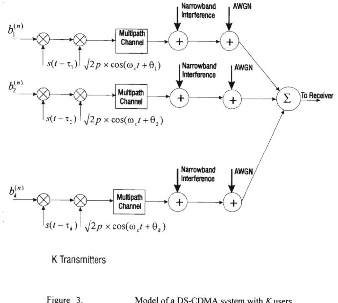
2.4 Model of Asynchronous CDMA System
Narrowband , AWGN
Interference
s(t-x.) Jlpxcosiaj+Q^ | Narrowband
(A W G NInterference
s(t - x,) I J2p x cos(©
cr + 9
2)
tfn)
< ? > — > < § > — •
Narrowband
Interference
s
(* ~
T* )
!yJ2p x cos(oo
cr + 0,)
Jo Receiver
K Transmitters
Figure 3.
M o d e l o f a D S - C D M A system with K users
2.5 Transmitter Model
A user k from the set {1,2,3,..A} transmits in the «th symbol interval t, where t e [(«- l)r,«r], a
complex signal:
**(')= 4A("K('- «•*). (5)
where Fis the length ofthe symbol period, b
k(n)e H is the transmitted complex data symbol and H is
the modulation symbol alphabet. The complex amplitude, denoted by A
k, is given by ^JE
ke
J*
k, E
kis the energy per bit ofthe corresponding real bandpass signal, <f)
kis the carrier phase and T
kis the delay
normalised so that if t falls outside the symbol period then Sk(t)= 0 otherwise J
o D S - C D M A system the signature waveforms are ofthe form:
Ne-l
s
k(*)= Z \
mY<J- ™T
C),
(6)
m=0
T
where S^istheiwthchipofuserA, Tc is the length of the chip period, Nc - — i s the processing gain,
c
and \j/{t) is the binary chip waveform.
2.6 Channel Model
It is assumed that the channel of User k is a linear filter with the following impulse response:
L
c
k<J)= I Sit- r
kly
ghl, (7)
where gkj is the complex channel coefficient, subject to the channel model. It could be, Rayleigh,
Rappaport or Rican. The relative delay for the multipath component / is denoted by T kl.
Besides being subjected to the response of the channel, User k is exposed to several other forms of interference; these include Additive White Gaussian Noise ( A W G N ) , Interference from other users
commonly k n o w n as M A I and NarrowBand Interference (NBI).
2.7 Processing the received signal
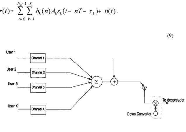
The above model, (see Figure 3) can be expressed as:
r
(0 = £ }_ b
k(n)A
ks
k(t-nT- r
k)-c
k(t)+ n(t)
«=0 k=\
Nh-\ K I
where Nb is the number of symbols in the packet and n(t) is AWGN.
In an A W G N channel g
k xcan be incorporated into the amplitude A
k(see Figure 4) and the received
signal becomes:
K0= I I b
k(n)A
ks
k{t- nT- r,)+ n(t).
n=0 k=l(9)
Userl
User2
User3 ,
UserK
Channel 1
C h s m l 2
C n a m w O
CharmelK
<±>
\
Down Converter
To despreader
Figure 4. Diagram showing the signals of Users 1 ..K at the antenna input at the
receiver.
2.7.1 Continuous Time Model
It has been s h o w n that the set of matched filter ( M F ) outputs sampled once in a symbol interval forms
sufficient statistics for the detection ofthe transmitted data [3]. T h e sampled output ofthe filter matched
to the/th users' /th multipath component is
^,(0= j r(t).s (t- IT- t„yk. (10)
This can be expanded by inserting r(t) from (8) to form :
* L (ft l)p r^,
^(0= III K(n)A
kg
klj s
k(t- nT- r
kJn fc=l /=1 W+Tjj
(H)
where ^ / (/) refers to the output ofthe matched filter of User/ in the /,„ multipath channel and n (i)
is equal to:
(ft l)r+ TjJ
*,(/)= J "(>H
re,('- iT- r
/re/? y/)^. (12)
In an ideal channel with no multipath fading this reduces to:
(13)
(ft 1 )7+ Tj
yjO)= J rit).
Sj(t- iT- Tj)dt.
J repiT+ X ,
In mis case (9) can be substituted into (13) to be expanded as [4]:
K (ft i)r+ TJ
yj0> I I KWA J s
k(t- nT- r
k)
SjJt- iT-
Tj)dt+ «,.(/)
J rep
n *= 1 /T+ r ,
Z X * * ( " H J *
J rep >n,(*K(f+ ('- n)T- T
k+ Tj)dt+ rijil) (14)
*= 1 -= /'it i o
These equations can be simplified by letting R be the cross correlation matrix between the received
R =
H
{0n
\l) Hf\0) 0
0
-Hl
n\l) Hl
n\0) Hl
n)(- 1)
0 ... H
(2 n)(l) H
{2 n\0) '
0
0
Tin)m
}
m
0
0 0
0
0
r(«)(15)
where
#,.*w= j^r?>/^+/T+ ^ - T
k)dt.
0
i = 0,±l
Using the result of (16), (14) can be rewritten as [4]
yjO)= t W+ m
jt
(- i)+1 HW^o)
4=1 A= 1
+ I Ui~ 1)^0)+
»y(0-*=l
where
*_(i> 6,(0-4
(16)
(17)
(18)
The output ofthe matched filter can be described in matrix notation as
y= RCAb+ n (19)
were R is the correlation matrix, C is the channel matrix, A is the amplitude matrix and b is the symbol
matrix. In an A W G N channel, the matrix C becomes the identity matrix.
2.7.2 Discrete T i m e Model
Figure 5 details a simplified block diagram ofa discrete Multiuser Receiver for C D M A applications. W e
can observe that it contains a down converter, which translates the RF spectrum to a low frequency
(10MHz or lower). This signal is then fed into an A/D converter and then into a digital signal processor
which detects and despreads the desired signal.
w
n-<g>
Sample & HoldJ A/D J«BM .
Processor
Local Qsdtlator(_)
/
From A/D,
L
Matched
Filter
Multiuser
Detector
PN J
To digital
demodulator
Figure 5. Block diagram of a discrete C D M A receiver.
The input to the receiver is given by :
A/4-l K L
K0= 1 1 I Un)A
kgkls
k{t- nT- r
k>l)+ n(t)
(20)after d o w n conversion and sampling, this input becomes.
r{mT
s)= til b
k(n)A
kgkJs
k(mT
s- nT- r
kJ)+ n(mT
s) (21)
« = 0 *=I /=!
This signal is then applied to the matched filter and Multiuser Detector. T h e symbol at the fth symbol
A:
yjjiO = S I l K ) . ^ K - iT-
Tj
)+n(mT,)
n *=1
K L
= 1 1 1
AM")gkMmT
s- nT- r
kJ).s (mT
a- iT- r
y/)+ n(mTs) (22)
n fel f=l
From the output ofthe matched filter the discrete signal is passed to the multiuser detection algorithm.
2.8 Performance Analysis of the Single User Receiver
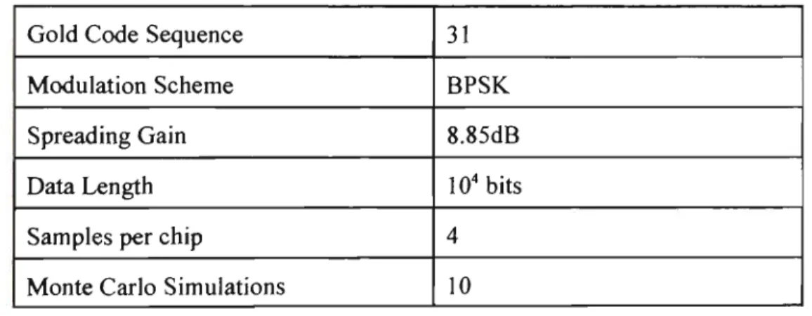
In order to evaluate the benefits of any ofthe proposed Multiuser Receivers, w e first need to accurately simulate the conventional receiver, and investigate its performance under various conditions. These results will form a reference for future simulations. A n y improvements that are m a d e with the multiuser receiver will be able to be compared directly against the conventional receiver.The simulations were set up using the following parameters :
Gold Code Sequence
Modulation Scheme
Spreading Gain
Data Length
Samples per chip
Monte Carlo Simulations
31
B P S K
8.85dB
10
4bits
4
10
Table 1 Parameters for the conventional Matched Filter Receiver.
Note that when the Multiuser receivers were simulated, the data length decreased to 103, to shorten the simulation execution time. In all simulations the system w a s asynchronous and it w a s assumed that there
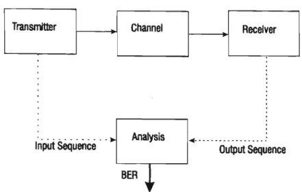
A n abstract diagram ofthe complete C D M A system is depicted in the figure below, and this diagram shows the sequence of events that are used to analyse the proposed receivers that are used in the C D M A system. T h e performance ofa digital communications system is evaluated by observing the Bit Error Rate ( B E R ) . T h e B E R of a system is calculated by comparing the transmitted data stream with the received data stream, counting the number of errors and then dividing the result by the total number of bits that were transmitted.
Input Sequence Output Sequence
Figure 6. Block diagram of B E R analysis.
The software package Matlab w a s used to simulate the receivers. T h e receivers were implemented as programs and then executed within the matlab environment. In all simulations c o m m o n modules were used, these included functions to generate the random data, implement the Gold C o d e Sequences and perform the spreading. Specialised functions that implemented the actual despreading and data detection were added to these c o m m o n modules to form the multiuser detector.
2.8.1 Conventional Single User Receiver
The Q function (23) is used to determine the B E R response ofthe receiver. A constant amplitude is assumed for each simulation.
^ ) = ^ > " ^ (23)
CD Q.
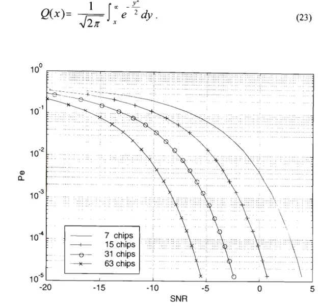
Figure 7. Theorectical B E R V s S N R for Codelengths of 63 31 15 7
The graph shown in Figure 7 details the theoretical B E R for a single user D S - C D M A system using spreading gains of 63,31, 15 and 7. Here w e can observe that the users in this system can transmit data when the system is subject to a high level of noise. Figure 7 shows that for an S N R of -5dB, and a spreading code length of 31 chips, the received B E R is equal to 10"3.
T o evaluate the B E R of an experimental single user system, the simulations were set up so that it was representative ofa practical spread spectrum system. User data were generated randomly and mapped to a B P S K format and then spread using spreading codes of several different lengths, which were 63,31,
Figure 8 shows the results for the practical system, it can be observed that they correlate well with those in Figure 7 . This indicates that the experimental system was set up correctly and that the results are accurate. F r o m table 1, as the data length is 10000 and the number of simulations is 10, this would provide a simulation accuracy of around 0.001. Figure 8 shows that for an S N R of-5dB the expected received B E R would be 10"3.
SNR
Figure 8. Experimental B E R V s S N R for C D M A System with Codelengths of 63, 31, 15 and 7
2.8.2 Simulation of a C D M A system with Near Far Effect
The N F E for the conventional receiver w a s simulated with 2,4 and 8 users.
This simulation is a very good illustration of h o w the performance ofthe conventional receiver using a matched filter correlator is limited by both the N F E and M A I . It shows that the receiver experiences difficulty in detecting weak wanted signals when a strong interfering signal is near by, and exceeds that ofthe spreading gain of any ofthe users in the system. It can be observed that as the number of users increased, the amplitude that was required by User 1 to achieve the same B E R as the 2 or 4 user case, had to be increased also.
J
[ ji i i i L J ',' • i = • »
-20 -15 -10 -5 0 5 10 15 20 Ratio of P(n)/P(1)indB
Multiuser Detection: an Overview
A review ofthe earlier and parallel w o r k regarding multiuser receiver design and multiuser demodulation
is presented in this chapter.
3.1 Conventional Receiver
In the conventional matched filter receiver, the decision device, which follows the matched filter, makes
one shot decisions, see Figure 10. That is, it estimates the transmitted symbol on the basis ofthe received
signal only in the interval corresponding to that symbol. Detection is not optimum in this approach as the
information that relates to overlapping symbols from other users is ignored. O p t i m u m detection of
asynchronous D S / C D M A signals requires that the whole received waveforms for all users at the output
r(t)
y>
> Decision
y
2^ Decision
y
3Decision
y
kDecision
Matched Filter Bank
Figure 10. Block diagram of Matched Filter.
3.2 L i n e a r M u l t i u s e r D e t e c t o r s
Linear equaliser type of multiuser detectors processes the matched filter output vector by a linear
operation. T h e performance ofthe decorrelating detector has been analysed by Verdu and Lupas in [5]
Decorrelating receivers for quasi-synchronous C D M A systems in A W G N channels without precise delay estimation have been proposed in [10,11,12] and for code acquisition in quasi-synchronous C D M A in [13].
The use ofa non adaptive receiver can result in wasted resources and unnecessary computations if only a subset ofthe possible users is active. In a practical communications environment, the set of users is
dynamic as users enter and leave the network. Unfortunately in the presence ofa n e w u n k n o w n user the performance ofthe decorrelating detector is severely degraded [14].
Adaptive decorrelating detectors were studied in [ 10] for asynchronous systems and implementations for synchronous systems were studied in [15]. Here they developed a simple adaptive decorrelating detector
by placing constraints on the set of spreading codes that are to be used by the active users. Both of these papers investigate different methods for updating the receiver parameters to cope with the presence of n e w u n k n o w n users. They take a total systems approach to address the issue of learning and integrating the knowledge o f a n e w transmitting user into the receiver structure. T h e paper discusses methods for determining the n e w users spreading codes with the use of training sequences. Blind algorithms are presented as a m e a n s of determining the n e w users spreading codes without the use of a training sequence. T h e paper also investigates further generalisation ofthe adaptive decorrelator to accommodate asynchronous transmissions by each ofthe active users.
Another linear equaliser that has also been researched extensively is the Linear Minimum Mean Squared Error ( L M M S E ) detector. This receiver takes into account the background noise and utilises the
knowledge ofthe received signal powers. It then attempts to maximise the Signal to Interference plus Noise Ratio ofthe (SINR) [16]. Centralised L M M S E receivers have been proposed for A W G N channels in [17,18], for fading channels in [19, 20]. T h e bounds for the N F R and S I N R ofthe L M M S E receiver in A W G N channels have been derived in [21 ]. A n improved L M M S E receiver, less sensitive to the time delay estimation errors, has been proposed in [22]. Receivers suitable for blind adaptation utilising the m i n i m u m output energy ( M O E ) criterion have been studied in [23,24]. It has been shown that the linear filter optimal in the M O E sense is equal to the linear filter optimal in the M M S E sense [25].
Other techniques for reducing the effects of MAI and Intersymbol Interference (ISI) were investigated by [26]. These include the : zero forcing block linear equaliser (zf-ble), Minimum Mean Square Error
Block, Zero Forcing Block decision Feedback Equaliser and the Minimum Mean Square Error Block
equaliser. Simulations are performed in a Multipath channel with Rayleigh fading. Observations where m a d e o n the system both with and without the application of Turbo Coding. Results showed an improvement in system performance w h e n Turbo Coding w a s used.
3.3 Adaptive Receivers
Receivers that are based on an adaptive algorithm often have the ability to adapt to their environment and learn about the dynamic and changing nature ofthe interference and channel.
The convergence ofthe adaptive algorithms for the LMMSE multiuser receivers has been considered in [27, 28, 29]. A modified adaptive multiuser receiver applicable to relatively fast fading
frequency-selective channels with channel state information has been proposed in [30]. Adaptive receivers do not require the signature or timing information ofthe other users [3 lj.These types of receivers are trained before data is transmitted with a k n o w n training sequence and continually adjusts the signature weights during data transmission. Advantages of this type of receiver include timing recovery, multiple access elimination and frequency selective fading suppression.
Adaptive transmitter and receiver structures [32] for asynchronous CDMA systems again assume that the adaptive receiver and transmitter have no knowledge ofthe signature waveforms ofthe other users. The
concept of an adaptive transmitter is based on feedback information from the corresponding receiver. The information obtained from the receiver is used to calculate the optimum transmitting signature and are adaptively adjusted according to the M S E criterion during the training period and during data transmission.
An adaptive receiver structure that is based on a matched filter followed by an adaptive equaliser is presented in [33]. This structure allows the receiver to adjust to its environment and reduce the effects
of interference and noise. T h e receiver structure is shown to offer a two-fold increase in capacity relative to the conventional receiver with perfect power control.
3.4 Adaptive Narrowband Interference Cancellation Techniques
spectrum systems in the presence of narrowband signals can be enhanced significantly through the use of active N B I suppression prior to despreading [34]. N o t only does active suppression improve error performance but it also leads to an increase in C D M A system capacity [35 ].
The adaptive notch filter is a technique that has been proposed to notch out or flatten the spectrum ofthe N B I signal. T h e adaptive notch filter places notches at the locations ofthe N B I , so to bring the level of
the interference d o w n to the level ofthe S S signal.
Estimation notch filters using adaptive techniques such as the Least Mean Squared (LMS) have been extensively researched. These filters are based on the knowledge that with wideband S S signals, the past values tend to be uncorrelated with the present or future values. With narrowband signals, the future values are correlated with the past values. Using this knowledge, the interfering signal can be estimated and subtracted out.
Narrow Band Interference rejection capabilities ofthe fractionally spaced equaliser is investigated by Davis and Milstein [36]. Here they describe an adaptive tapped delay line equaliser that operates in a D S
-C D M A receiver, where the taps are adapted to minimise the m e a n squared error. The overall effect is to whiten the noise and mitigate the effects of both M A I and N B I .
The performance of bom optimal and adaptive interference suppression filters for DSSS systems is simulated by M a m m e l a [37]. T h e simulations include the linear M step prediction and interpolation filters and as well as the L M S , K a l m a n algorithms. It is demonstrated that linear filters work well if the interference bandwidth is a fraction ofthe signal bandwidth.
For the case ofa sudden parameter jump or new interference, Lee and Lee [38] suggest a gradient - search fast converging ( G F C ) algorithm. T h e transient behaviour ofthe receiver using a G F C adaptive filter is
investigated and compared with that of receivers using an L M S or a lattice adaptive filter. They maintain that the G F C is superior for suppressing irregular hostile jamming in D S - C D M A . For better stability, H e , U i , D a s and Saulnier [39] discuss the modified L M S algorithm and lattice filter structures comparing their B E R performance and convergence characteristics.
and simple implementation (in comparison to multiuser detection) while at the same time alleviating the near-far problem to a large extent. T h e channel output is first passed through a filter matched to the chip waveform and then sampled at the chip rate. D u e to the complexity and coefficient noise that is associated with systems with large spreading gains simpler structures with few components are proposed.
3.5 Interference Cancellation
Spread spectrum, by its very nature, is an interference tolerant modulation scheme. However, there are situations where the processing gain is inadequate and interference-rejection techniques must be employed. This is especially true for direct sequence spread spectrum, which suffers from the near far problem.
The idea of interference cancellation is to estimate the multiple access and multipath induced interference and then subtract the interference estimate from the M F output [41]. T h e interference cancellation can
be derived as an approximation of the (optimum) M L S D receiver with the assumption that the data, amplitude, and delays ofthe interfering users are known.
3.5.1 Successive Interference Cancellation
T h e need for a simple but yet effective solution to the problem of multiuser detection ( M U D ) is presented in [42] by Holtzman. T h e author discusses a method k n o w n as successive interference cancellation as a relatively simple form of M U D and investigates h o w it can be practically implemented in a real system. Problems that impede its implementation are discussed and solutions for these problems are investigated.
Successive Interference Cancellation (SIC) takes a serial approach to reducing the interference that is caused by the M A I . This is done by recreating separate estimates ofthe multiple access and multi-path
induced interference at the receiver, so that its influence on each user can be subtracted out. This is performed on a user by user basis [43 ] using either Soft Decision (SD) or Hard Decision ( H D ) techniques.
The ordering ofthe powers ofthe various users is a problem in relatively fast fading channels as they must be updated frequently. SD-S1C has been considered in [44], and H D - S I C in [45, 46]. T h e SIC for
poor. T h e reason for that is that the SIC is initialised for User 1. If the M A I estimation is poor in the cancellations, the estimation errors will propagate to all users. T h e SIC has good performance in systems where the powers ofthe users differ significantly. T h e effects of delay estimation errors for the SIC has been considered in [48].
Johansson and Svensson [49] investigates interference cancellation in DS-CDMA systems that support multiple data rates. T w o methods for implementing multiple data rates are considered, one is the use of mixed modulation and the other is the use of multi-codes. They introduce and analyse a n e w approach that combines these multiple data rate systems together with a single and multistage non-decision directed interference canceller. T h e IC schemes that are used by the authors are generalisations and extensions of the successive (serial) IC technique. T h e analysis w a s performed in an A W G N and Rayleigh fading channel. Their analysis indicated that the IC schemes used in the mixed modulation or multi-code systems yielded a performance that w a s close to the single B P S K user bound and gave the prospect of an overall system improvement compared to systems using conventional matched filter techniques.
The performance of an adaptive successive serial-parallel CDMA cancellation scheme in flat Rayleigh fading channels has been studied in [50]. They use a sliding block w i n d o w ranker and a bank of successive serial - parallel cancellation receivers to reduce the effects of M A I . T h e serial canceller requires that the users amplitudes be ranked in order of signal strength. T h e proposed receiver uses a serial canceller followed by a parallel canceller. T h e authors consider the reverse channel ofa single cell C D M A system with perfect power control, the system is simulated in a flat Rayleigh fading channel using both perfect and non-perfect channel estimation.
3.5.2 Parallel Interference Cancellation
T h e application ofthe H D - P I C to multiuser delay estimation in relatively fast fading channels has been considered in [59]. T h e S D - P I C receiver has been considered in [60]. T h e effect of estimation errors on the performance ofthe H D - P I C receiver has been considered in [61].
An efficient feedback receiver structure for the coherent demodulation of K asynchronous CDMA signals is investigated in [62]. Through the use of feedback, the receiver provides protection for the synchronising loops against the effects of strong interfering signals.
Latva-aho and Lilleberg in [51] investigate Parallel interference cancellation (PIC) based channel parameter estimators for frequency selective fading channels for the uplink in code division multiple access ( C D M A ) mobile communication systems. They note that the performance of PIC based algorithms depends heavily o n the quality ofthe multiple access interference estimates, which can be improved by using adaptive channel estimation filters. T h e performance of two adaptive complex channel estimation filters w a s verified in a fading channel by computer simulations. According to their results, the PIC based adaptive channel estimators outperformed the conventional matched filter method, the successive interference cancellation and decorrelation based adaptive channel estimators.
In [63], the authors describe a multistage PIC for the uplink of an asynchronous coherent DS/CDMA mobile radio system. A n important design parameter of this IC is the low processing delay that is required to realise an accurate closed loop Transmission Power Control. Computer simulations reveal that the performance ofthe t w o stage P I C can enhance the cell capacity by approximately 2.2 times more than a Matched Filter in a multipath Rayleigh fading channel. T h e PIC includes moderation factors to control the interference replica to a level that is proportional to the reliability of that replica.
A new flexible multiuser detection scheme for DS-CDMA using multistage detection algorithms and m a x i m u m likelihood detection is proposed in [64]. It is based on initialising the multistage detection scheme with several different starting vectors. Using parallel computations the processing delay w a s able to be limited to reasonable values.
Kobayashi and Suzuki [66], proposes an interference cancellation method that incorporated a method for estimating the channel in a multipath environment for slotted A L O H A . They performed computer simulations using a frequency selective Rayleigh fading model.
Divsalar et al present an improved non linear PIC that is based on partial cancellation [67]. They show that in the early stages of interference cancellation, where the interference estimate is poor, the tentative
data decisions are less reliable than those ofthe following stages. T h e authors note that it is preferable not to cancel out the entire amount ofthe estimated M A I , but only a fraction of it. A s the interference canceller (IC) operation progresses, the estimates of the M A I improve and the amount of the "real" interference that is being removed also increases.
Rapport and Shan in [68] investigate the technique of partial parallel interference cancellation further. They compare the performance of both the partial PIC and the standard PIC under various near far effects
4 Multiuser Detection: an in-depth analysis
The detection of W - C D M A signals can be improved by the use of Multiuser Detectors. In multiuser detection, the code (signature) and timing information and in s o m e instances possibly amplitude and phase information of multiple users can be jointly used to improve the reliability of detection for each individual user. Multiuser Detectors are usually implemented at the base station where there is knowledge of all ofthe users' codes.
There have been many proposed receivers, they range from the optimal receiver structure that was proposed by Verdu; based on Maximum-Likelihood Sequence Detection, to the less complex, sub optimal structures that approximate the optimal receiver. Most of these detectors can be classified into one of three categories. These include:
1. Linear Detectors
2. Adaptive Linear Receivers
Linear multiuser detectors apply a linear mapping at the output ofthe decision device ofthe conventional detector. This mapping produces n e w set of outputs which will provide better performance and reduce the effect of M A I that is seen by each user. T h e adaptive linear receiver uses an error term to control the weights that are applied to the linear FIR filter. T h e error term and weights are updated every symbol. Subtractive Interference Cancellation relies upon estimates ofthe users' amplitudes to generate replicas ofthe interference. This interference term is then subtracted out. N o n linear detectors use neural networks or a nonlinear decision device like the hyperbolic tan function, tanh, to detect the spread spectrum signal.
In the remainder of this chapter we will firstly look at the optimum receiver and then briefly analyse each ofthe detectors that are listed above and finally discuss the advantages and disadvantages of each of
them.
4.1 Optimum receiver
The conventional matched filter receiver, estimates the transmitted users signal on the basis of the received signal, only in the symbol interval. In this approach, the detection of desired users symbol is not optimum as the information that relates to the interference coming from the other users overlapping symbols is ignored. O p t i m u m detection of asynchronous D S / C D M A signals, requires observation ofthe whole received waveform for all users at the output ofthe matched filter.
For optimum demodulation, it is assumed that the receiver has the information about the signature waveforms for each user as well as knowledge ofthe time delays, phase shifts and amplitudes.
The minimum error probability receiver must find the most probably transmitted data symbol for all users for all symbol intervals. Each minimisation computes a metric for all possible interfering data symbol
combinations. Although a dynamic programming algorithm can be devised to implement the m i n i m u m probability of error detector, the required number of operations grows exponentially with the number of users.
O p t i m u m receivers can then be designed to select the bit sequence
b =
h(-M)
L h(r M)
b
x{M)
b
k{M)
(24)
which maximises the conditional probability [1]
F[b\r(t)]
(25)If w e assume that the transmitted bits are independent and equip probable, maximising the probability in (25) is equivalent to maximising the likelihood function [1]:
-JLf
/>[r(0|b]= Ce
2
°
2
°
ykUyj, bfErSk{t) k=\
dt
for tE [0,T] (26)
,2 .
where C is a constant and <J is the noise power, yk(t) is the output ofthe kih. matched filter, Ek is the
amplitude ofthe users' waveform, b and Sk(t) are the bit sequence and the signature respectively.
Although a dynamic programming algorithm can be devised to implement the likelihood function in (26), the required number of operations grows exponentially with the number of users. A n example of dynamic programming is the Viterbi algorithm. T h e input to this algorithm is the output samples from the matched filters, it operates on a trellis and its complexity is proportional to 21"1 users'. This algorithm selects a sequence V so that the likelihood function in (26) is maximised.
4.2 Sub-Optimum Detectors
The optimum receiver is exponential in complexity in the number of users. For example, in a system with 50 users, the number of computations that are required per symbol would be in the order of magnitude of 0(250), which is a very high number. For practical implementation this extreme complexity has to be reduced to a reasonable level even if the performance is somewhat degraded from the optimum one. A block diagram of a basic multiuser receiver is detailed in Figure 9.
r{t)
-* MF
-* MF
-H MF
.?.('<
>s(0
r-Y
V
3(0
-* MF r-^V~
>>A0
-Y-Multiuser
Linear Detecto
Multipath
combing &
Detection
Multipath
combing &
Detection
Figure 9. Diagram of a linear multiuser detector.
Multiuser receivers that process the matched filter output by a linear operation are called a Linear Multiuser receiver. The output of these types of receivers are given by the expression
L
m=Ly. P7)
were y is the output vector of the matched filter, L is the linear operation that is performed by the Multiuser Detector, and L,m is the output ofthe matched filter. Different choices ofthe equalisation matrix
L yield different types of multiuser receivers. For example, the identity matrix L- /#4j_will be
4.3 T h e Decorrelating Detector
The optimum receiver achieves low bit error probability at the expense of high computational complexity. W h e n the number of users is large, it is desirable to use a simple but reliable sub-optimum detector. The linear decorrelating detector can significantly outperform the conventional receiver. It is a multiuser receiver that is near-far resistant it has sub-optimum performance and its complexity increases linearly with the number of users. This detector applies a linear transformation, which is based on the inverse of the correlation matrix, R. to each output vector ofthe conventional matched filter in order to decouple the users' data.
Kec = R
l(28)
Consider an asynchronous C D M A system that consists of K users, with each user being assigned a
signature waveform, sk(t), where k — 1...K, and each signature waveform is restricted to a symbol
interval T, and is linearly independent. The input data from each user is a binary sequence, from the
symbol alphabet, H . If w e assume that the input vector is given by b = \bx,... bk ] where bk € H ,
m e n from (19) the output of a conventional matched filter detector for a K user C D M A system can be describes as follows :
jp= RAb+ n (29)
Here, R is the crosscorrelation matrix, A is a diagonal matrix that contains the amplitude information of the A: users', b contains the users' information bits and n is the noise vector.
Multiplying the output vectory by Rl, we get
R-'y= R
J(RAb+ n)
= Ab+ z. (
3°)
9 —9
The term z is a Gaussian noise vector with the autocorrelation matrix Rz = a R .It represents an
increase in the output noise ofthe decorrelating detector. This level is always greater than or equal to the power that is associated with the noise term that is present at the output ofthe matched filter. Near
The probability that the kth, input is recovered correctly [9] is :
(31)
PeM)-- >
A
*
*^<T
2(R-
ly
(f- \)K+ k Jwhere Ak is the amplitude of User k.
T o mitigate the effects of M A I , the decorrelating detector does not require any amplitude information of any ofthe users in the system. It uses the information ofthe users signature waveforms to form the crosscorrelation matrix R.
A significant disadvantage of this type of detector is that the computations that are required to invert the correlation matrix R are difficult to perform in real time. There have been several suboptimal approaches
to implementing the decorrelating detector. M a n y of them entail breaking up the detector into more manageable blocks so that the matrix inverse m a y be computed. However, whichever sub-optimal decorrelating detector technique is used, the computational effort that is required is still quite significant.
4.4 Minimum Mean Squared Error (MMSE) Detector
Another detector that performs a linear mapping ofthe output ofthe matched filter is the M i n i m u m M e a n
Squared Error ( M M S E ) Detector. This detector takes into account the background noise and makes use
ofthe received signal powers of all ofthe users [16]. The object of this receiver is to minimise the error between the actual output ofthe conventional matched filter and the soft output ofthe decision device or the linear mapper [18].
A mapping L is applied to the output v ofthe conventional detector. The MMSE based detector ensures
that the performance criterion, £ H^- b) \b- bj\ is minimised, where the estimate b is given by:
b= Ly (32)
In other words this detector forces the expression
E{\b
k
(n)- Lyf) (33)
The actual equalisation matrix that is used in the mapping ofthe output ofthe matched filter is
'MMSE
(
- V
R +
V
2A
l)
= (*+ f)
-1 (34)Where R is the cross correlation matrix, NQ is the received noise power and A is the received signal
power. In the absence of noise, the MMSE estimate becomes b= R y . At the other extreme, i.e.,
whenN0> > A,L reduces to the identity mapping and the MMSE detector reduces to the
conventional receiver.
In (34) noise and amplitude information is added to the correlation matrix R . This type of detector is similar to that ofthe decorrelator. In this case it is takes into account the background noise, the amount
of modification is directly proportional to the background noise. With this detector, an inversion of R cannot be performed without s o m e sort of noise enhancement and performance degradation. Hence the M M S E detector balances the desire to decouple users and completely eliminate any M A I with the desire to keep the effect ofthe background noise low.
The probability ofthe Mi user's z* bit is detected in error is given by [18]:
P
MMSE
=JhftsgrtLy)]^^ - l\b
k(i)= 1
= Pii
(
-
# 0R +
V '
2A
2J
n
f> l)K+ k
( N
R+ "°
2A
2J
-1
RAb
(i-\)K+k
Since the noise component
( N V
1
R+ -%
I 2 A
2J
n
is Gaussian with zero mean and variancer> 1)A:+ k
equal to the f(i-l)K+kjih diagonal element of E
R +
V 2A
l)
N V
1
/
•L V n 7
N
nn\ R+
iV°
A- 1
^ 2 A
2J
N,
N
nR+
K 2A
L)
•i.
+
N
rV
12A
2J
(36),MMSEs •
Pk ( i) can be expressed as a sum of Q functions . From [18], the f(i-l)K+k]th diagonal entry ofthe
N»
^ o ( matrix m (36) can be denoted as — — and the f(i-l)K+kJth row of the matrix R +
2a { 2A
Z)
R as
[S^Sn-gMK^1^^ Pk ' ( 0
c a n
be written as
iMMSE
P
k MM*\i)= 2
- MK+lI Q
bkU)(lU))e{- U }
g(r-i
)K+k+ 1 gjb
kU)(q(j))
j*(/- \)K+ k
2a
(37)
Tj{j) is the integer part ofthe ratio ofj/K, where K is the number of asynchronous users, k(j ) is equal
to j mod K. This can be calculated if the mapping L is known.
Due to the fact that this type of detector takes the effect of background noise into account, the overall
system performance and probability of error will be better than that ofthe decorrelating detector. As the background noise converges to zero the performance of this receiver will approach that of the
The linear decorrelating detector and the M M S E both have the ability to provide substantial system improvements over the conventional receiver for a C D M A environment. These improvements include the rejection of M A I and an increase in overall system capacity.
The linear operation ofthe decorrelating detector uses information contained in the correlation matrix to reduce the effects of M A I and as such no amplitude information is required. A s the M M S E receiver
reduces the effect ofthe background noise this type of linear receiver requires that the amplitudes or signal powers ofthe other users' are estimated. O n e c o m m o n feature ofthe M M S E detector and the linear equaliser is that the preliminary estimate of the transmitted bit sequence obtained using the linear transformation L is biased and dependent on the estimation ofthe signal levels ofthe interfering users in the system . This complicates the analysis and leads to a performance that depends on the interfering signal power.
As these types of detectors implement a linear mapping at the output ofthe matched filter, the actual complexity of them is linearly proportional with the number of users. This is significantly lower than that
ofthe optimum detector w h o s e complexity increases exponentially with the number of users.
The MMSE detector that is described above operates on the entire sequence at once. When M is large, as it will almost always be in practice, the resulting detection delay will be unacceptably large. The detector can be modified to incorporate a practical constraint on the size of the delay. This can be implemented by dividing the entire sequence of M bits up into subsequences, by the insertion of reference symbols.
Due to the many attractive features of these types of detectors, these types of receivers have been the focus of m u c h research. Unfortunately they also have several disadvantages including noise
5 Adaptive Linear Receivers
In this section the application ofthe Adaptive Linear Receiver as a multiuser receiver is investigated. T o
be able to implement this type of receiver, both in a computer simulation and in a Digital Signal
Processor, the knowledge of adaptive algorithms is required. In the next section, the Least M e a n Squared
( L M S ) algorithm is analysed and the coefficient update equations are derived. This then forms the basis
ofthe adaptive receiver which is analysed in section 5.5.2.
5.1 Adaptive Filters
Adaptive Filters have the ability to operate satisfactory in u n k n o w n environments and conditions and can
track time varying input data. T h e y have a broad range of applications, including communications, radar
and control. In communication receivers and systems, the adaptive filter finds extensive use in eliminating
noise and interference as well as enhancing the desired signal and improving the B E R . Interference