Technical Bulletin
Upgrading Strata DK Systems
to DK424 Release 3.2
This bulletin provides instructions for replacing a Strata DK14, DK16e, or DK40 system with a DK424 system, Release 3.2. It also explains how to upgrade a DK280 or DK424 system, Release 1~3 to a DK424 system, Release 3.2. The following important items must be considered when performing the above changes and/or upgrades.
Important! After you install Release 3.2 software on an RCTU PCB, you must initialize the RCTU and re-program the customer database. (See following procedures.)
Notes
● DK Release 1 and 2 RCTU PCBs cannot be upgraded to Release 3.2.
● DK Release 3 RCTU PCBs with Release 2.0, 3.0 or 3.1 software can be upgraded to Release 3.2.
There are two procedures to upgrade a DK system to Release 3.2.
Use Procedure 1 to upgrade RCTU Release 3.0 or 3.1 to Release 3.2. (In this case, the RCTU PCB does not change).
Use Procedure 2 when you upgrade:
♦ DK14, DK16e, or DK40 or RCTU Release 1 or 2 hardware to a DK424 Release 3 RCTU with Release 3.2 software.
♦ a Release 3 RCTU with R2.0 software to Release 3.2 software on the same or larger Release 3 RCTU.
♦ Release 3.0 or R3.1 software to Release 3.2 software on a larger Release 3 RCTU PCB.
Notes
● DK14, DK16e, and DK40 upgrades require DKAdmin R4.0. 280Admin does not support these systems.
● When you use Admin/Backup, select Release 3 to create a Release 3.1 or 3.2 customer database from the Maintain Customer File menu.
TBDK-0012 May 30, 1998
Prel
imi
nary and
Con
fid
ent
ial
DK424 Release 3.2 Upgrade – Procedure 1
Note To create a new customer from the Maintain Customer File menu, select
Release 3 at the prompt to Enter a processor release level.
1. Use 280Admin/Backup R3.1 or DKAdmin/DKBackup R4.0 to download the existing Release 3.0 or 3.1 customer database: Start from the Backup/Restore Data menu, press F2, then press F3.
2. Power down the Strata DK and change to the Release 3.2 ROMs or flash memory on the Strata DK processor per instructions for “Upgrading Hardware to DK424 Release 3.2” on Page 3 of this bulletin.
3. From the programming telephone, run Program 91-9 twice.
4. Also from the programming telephone, use Program 76 and/or Program 03 to set the correct parameters for the TTY port.
5. Upload the Customer database that was downloaded in Step 1 to the Release 3.2 processor per the Admin/Backup instructions: Start from the Backup/Restore Data menu and press F2, then press F4.
DK424 Release 3.2 Upgrade – Procedure 2
1. Use 280Admin/Backup, Release 3.1 or DKAdmin, DKBackup, Release 4.0. to download the customer data from the currently installed processor.
Save this customer data as a backup in case you must re-install the current processor and/ or processor ROM/flash memory release level.
2. Use Admin or Backup to create a new customer for the upgrade.
Important! When creating a new customer, select the currently installed processor type and Release 1, 2, or 3. Release 3.1 software can be upgraded by selecting Release 3.
3. Use Admin or Backup to select the customer created in Step 2 (not Step 1).
4. Select the Upgrade (F5) function from the Backup/Restore Data menu to start the upgrade procedure.
5. Choose “Yes” if prompted to Upgrade for DK280 R3. (This displays only if you are upgrading from RCTU Release 1 or 2.)
6. Choose “Yes” when prompted to Backup From DK First.
7. After the current data is downloaded, follow the DKAdmin/DKBackup screen instructions to change the processor and/or ROMs or flash memory. The procedure for changing ROMs and flash memory per the instructions “Upgrading Hardware to DK424 Release 3.2” on Page 3.
8. Re-initialize the system.
Important! When changing the processor and ROM or flash memory for the “Upgrade to” processor, you can add an RSIU to complete the upgrade at 9600 bps. However:
Prel
imi
nary and
Con
fid
ent
ial
● Do not change the order in which the PCBs are installed in the slots.● Be sure to reinitialize the “Upgrade to” processor twice. Set the DK TTY port
with Programs 76 and 03.
9. Continue with the upgrade procedure as prompted by the Admin or Backup screens until complete.
Notes
● If you are using 280Admin, Release 3.1, you can backup and restore or upgrade Release 3.2 processors by selecting Release 3.0 when creating a customer database. However, 280Admin, Release 3.1 screens do not display Strata DK Release 3.2 program additions. Release 3.2 programs must be set using the programming telephone.
● DKAdmin, Release 4.0 provides screens to access all DK Release 3.2 programs.
Upgrading Hardware to DK424 Release 3.2
1. Power down the system before removing and installing the processor card(s).
Figure 1 shows the slot placement of the processor cards. Remove only the RCTUA,
RCTUBB, RCTUD, or RCTUF.
2. Remove the MOH connection, if required.
RCTUBB, RCTUA, or RCTUD
RCTUD only To RSIU if installed
RCTUBA or RCTUC
Slot R11 Slot RCTU (Base Cabinet)
P3 P2
P11 P2
Heartbeat LED
1394
RCTUF
To RSIU if installed
RCTUE
Slot R11 Slot RCTU (Base Cabinet)
P3 P2
P11 P2
Heartbeat LED
1924
Prel
imi
nary and
Con
fid
ent
ial
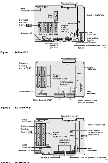
3. Remove the RRCS DTMF PCB on the RCTU card, if equipped (see Figures 2~5).Backplane Connector P5 P4 BATT ON OFF P3 P2 P11 VR1 CBRUK IC12 Feature Upgrade Connectors (not used) RRCS Connectors RCTUA3 RCTUA3 RRCS Connectors U3 Heartbeat LED P1 Tone ROM IC16 IC15 Program ROMs IC15, 16, 17, and 18
BGM and MOH Interface (RCA Jack) RKYS Key Socket Install in “RCTU” Slot
BGM/MOH Volume Control To RSIU P12 RAA3-6 RAA3-5 IC18 IC17 RAA3-8 RAA3-7 3222 6 F Software Version R3.2 =
Figure 2 RCTUA PCB
Backplane Connector
IC10
P1
Program ROMS
IC9, 10, 11, and 12 To RCTUBA/RSIU Connectors
CD5 RCTUBB3
CBRUK
Heartbeat LED P2 P3 IC9
U3
RKYS Key Socket
Ribbon Cable to RCTUBA (and RSIU if installed) Ribbon Cable to RCTUBA
Install in “RCTU” Slot RBA3-0 RBA3-9 RBA3-2 RBA3-1 IC12 IC11 RCTUBB3 3224 6 F Software Version R3.2 =
Figure 3 RCTUBB PCB
Backplane Connector P8 P7 P6 P5 IC10 RRCS Connectors RRCS Connectors P1 Program ROMS
IC9, 10, 11, and 12 RCTUC/RSIU Connectors
CD5
CBRUK
Heartbeat LED
To RCTUC To RCTUC (and RSIU, if installed) P3 P2 IC9 U3 U4 RKYS Key Socket Place jumper in ON position before installing PCB Install in “RCTU” Slot
CBRUK RCA3-0 RCA3 -9 RCA3-2 RCA3-1 IC12 IC11 BATT
ON P9OFF
3223 RCTUD3 6 F Software Version R3.2 =
Prel
imi
nary and
Con
fid
ent
ial
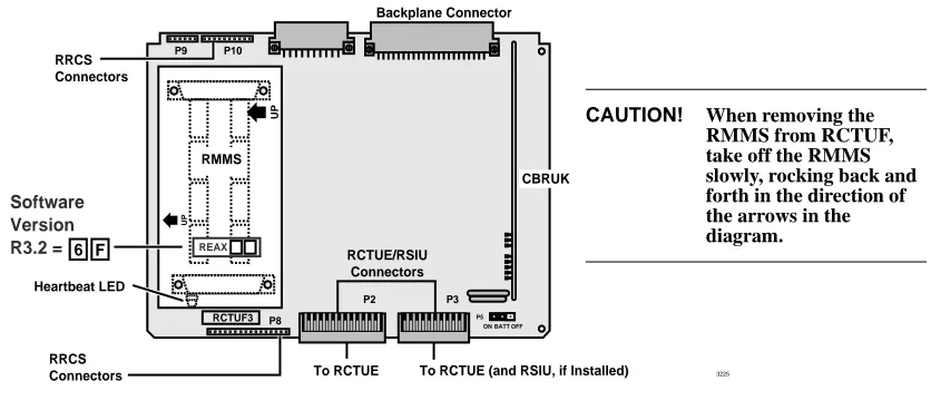
4. Using a small screwdriver, carefully remove the four ROMs (see Figure 6) or use your fingers to gently remove the flash memory. Replace with the equivalent ROMs or flash memory in the upgrade kit.
P9 P10
3225
UP
UP
RMMS
REAX
RCTUF3
Backplane Connector
RRCS Connectors
RRCS Connectors
Heartbeat LED
RCTUE/RSIU Connectors
To RCTUE To RCTUE (and RSIU, if Installed)
P8
P2
CBRUK
P3
BATT ON OFF P5
6 F
Software Version R3.2 =
Figure 5 RCTUF PCB with RMMS
CAUTION! When removing the RMMS from RCTUF, take off the RMMS slowly, rocking back and forth in the direction of the arrows in the diagram.
Designates Front of Chip
Front Direction Marker Silk-screened on PCB
IC Socket Mounted on Processor's PCB (back)
(front)
Turn Very Gently
2514
Do Not Break IC Socket
Do Not Scratch PCB
CAUTION! Be careful not to break the IC socket
or scratch the PCB trace.
Prel
imi
nary and
Con
fid
ent
ial
5. Re-install the RRCS DTMF PCB, if required.Note If there are battery straps on the PCB, make sure that they are placed in the “on” position for the processor card(s) to avoid losing your data.
6. Re-insert the processor card(s), reconnect the ribbon cables and MOH connection if necessary. If an RSIU card is being added, shift the card positions accordingly. Without changing the order in which the PCBs are installed, add the RSIU PCB in slot 11 and change the ribbon cable to connect the RCTU PCB(s) to the RSIU.
Note any changes needed to accommodate the displaced card if necessary. If this creates extensive changes, it may be better to upgrade without adding the RSIU, get the system working, and then adjust the card positions to add the RSIU PCB.