Conference Chair: Prof.Dr.G.ManojSomeswar, Director General, Global Research Academy, Hyderabad, Telangana,
A Novel Integrated Attestation Graph Analysis Scheme for
Enhancing Result Quality and Higher Attacker Pinpointing Accuracy
Ganya Rakesh
1; Mr.M.Deena Babu
2& Prof.Dr.G.Manoj Someswar
31
M.Tech.(CSE) from Narasimha Reddy Engineering College, Affiliated to JNTUH, Hyderabad, Telangana,
India
2
M.Tech. (CSE), Assistant Professor, Department of CSE, Narasimha Reddy Engineering College,
Affiliated to JNTUH, Hyderabad, Telangana, India
3
B.Tech., M.S.(USA), M.C.A., Ph.D., Principal & Professor, Department Of CSE, Anwar-ul-uloom College
of Engineering & Technology, Affiliated to JNTUH, Vikarabad, Telangana, India
ABSTRACT:
Software-as-a-service (SaaS) cloud systems enable application service providers to deliver their applications via massive cloud computing infrastructures. However, due to their sharing nature, SaaS clouds are vulnerable to malicious attacks. In this paper, we present IntTest, a scalable and effective service integrity attestation framework for SaaS clouds. IntTest provides a novel integrated attestation graph analysis scheme that can provide stronger attacker pinpointing power than previous schemes. Moreover, IntTest can automatically enhance result quality by replacing bad results produced by malicious attackers with good results produced by benign service providers. We have implemented a prototype of the IntTest system and tested it on a production cloud computing infrastructure using IBM System S stream processing applications. Our experimental results show that IntTest can achieve higher attacker pinpointing accuracy than existing approaches. IntTest does not require any special hardware or secure kernel support and imposes little performance impact to the application, which makes it practical for large-scale cloud systems.
KWYWORDS: Web services architecture (WSA); National Institute of Standards and Terminology (NIST);
Infrastructure-as-a-Service (IaaS); Platform-as-a-Service (PaaS); and Software-as-a-Service (SaaS); Trusted Platform Module (TPM)
INTRODUCTION
Cloud computing is the use of computing resources (hardware and software) that are delivered as a service over a network (typically the Internet). The name comes from the common use of a cloud-shaped symbol as an abstraction for the complex infrastructure it contains in system diagrams. Cloud computing entrusts remote services with a user's data, software and computation. Cloud computing consists of hardware and software resources made available on the Internet as managed third-party services. These services typically provide access to advanced software
applications and high-end networks of server computers.[1]
Conference Chair: Prof.Dr.G.ManojSomeswar, Director General, Global Research Academy, Hyderabad, Telangana,
The goal of cloud computing is to apply
traditional supercomputing, or high-performance computing power, normally used by military and research facilities, to perform tens of trillions of computations per second, in consumer-oriented applications such as financial portfolios, to deliver personalized information, to provide data storage or to power large, immersive computer games.[2]
The cloud computing uses networks of large groups of servers typically running low-cost consumer PC technology with specialized connections to spread
data-processing chores across them. This
shared IT infrastructure contains large pools of systems that are linked together. Often, virtualization techniques are used to maximize the power of cloud computing.[3]
Characteristics and Services Models: The salient characteristics of cloud computing based on the definitions provided by the National Institute of Standards and Terminology (NIST) are outlined below:
On-demand self-service: A consumer can unilaterally provision computing capabilities, such as server time and network storage, as needed automatically without requiring human interaction with each service’s provider. [4]
Broad network access: Capabilities are available over the network and accessed through standard mechanisms that promote use by heterogeneous thin or thick client platforms (e.g., mobile phones, laptops, and PDAs). Resource pooling: The provider’s computing
resources are pooled to serve multiple consumers using a multi-tenant model, with different physical and virtual resources dynamically assigned and reassigned according to consumer demand. There is a sense of location-independence in that the customer generally has no control or knowledge over the exact location of the provided resources but may be able to specify location at a higher level of abstraction (e.g., country, state, or data center). Examples of resources include storage,
processing, memory, network bandwidth, and virtual machines.
Rapid elasticity: Capabilities can be rapidly and elastically provisioned, in some cases automatically, to quickly scale out and rapidly released to quickly scale in. To the consumer, the capabilities available for provisioning often appear to be unlimited and can be purchased in any quantity at any time.
Measured service: Cloud systems automatically control and optimize resource use by leveraging a metering capability at some level of abstraction appropriate to the type of service (e.g., storage, processing, bandwidth, and active user accounts). Resource usage can be managed, controlled, and reported providing transparency for both the provider and consumer of the utilized service[5].
Figure 2: Characteristics of cloud computing Services Models:
Conference Chair: Prof.Dr.G.ManojSomeswar, Director General, Global Research Academy, Hyderabad, Telangana,
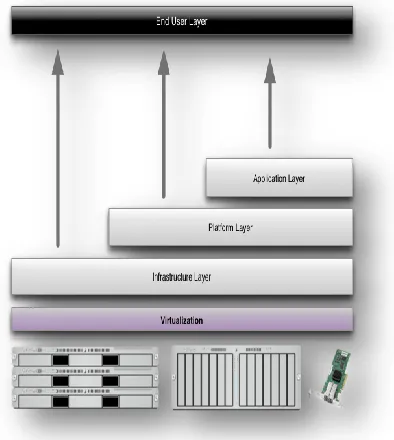
Figure 3: Structure of service models Benefits of cloud computing:
1. Achieve economies of scale – increase volume output or productivity with fewer people. Your cost per unit, project or product plummets. 2. Reduce spending on technology
infrastructure. Maintain easy access to your information with minimal upfront spending. Pay as you go (weekly, quarterly or yearly), based on demand.
3. Globalize your workforce on the cheap.
People worldwide can access the cloud, provided they have an Internet connection. 4. Streamline processes. Get more work done in
less time with less people.
5. Reduce capital costs. There’s no need to spend
big money on hardware, software or licensing fees.
6. Improve accessibility. You have access anytime, anywhere, making your life so much easier!
7. Monitor projects more effectively. Stay within budget and ahead of completion cycle times.
8. Less personnel training is needed. It takes fewer people to do more work on a cloud, with
a minimal learning curve on hardware and software issues.
9. Minimize licensing new software. Stretch and grow without the need to buy expensive software licenses or programs.
10. Improve flexibility.You can change direction without serious “people” or “financial” issues at stake. [7]
Advantages:
1. Price: Pay for only the resources used.
2. Security: Cloud instances are isolated in the network from other instances for improved security.
3. Performance: Instances can be added instantly for improved performance. Clients have access to the total resources of the Cloud’s core hardware.
4. Scalability: Auto-deploy cloud instances when needed.
5. Uptime: Uses multiple servers for maximum redundancies. In case of server failure, instances can be automatically created on another server. 6. Control: Able to login from any location.
Server snapshot and a software library lets you deploy custom instances.
7. Traffic: Deals with spike in traffic with quick deployment of additional instances to handle the load.[8]
LITERATURE SURVEY
Virtualization technology is becoming increasingly common in datacenters, since it allows for collocation of multiple workloads, consisting of operating systems, middleware and applications, in different virtual machines (VMs) on shared physical hardware platforms. However, when coupled with the ease of VM migration, this trend increases the potential surface for security attacks. Further, the simplified management of VMs, including creation, cloning and migration, makes it imperative to monitor and guarantee the integrity of software components running within VMs.[9]
Conference Chair: Prof.Dr.G.ManojSomeswar, Director General, Global Research Academy, Hyderabad, Telangana, strong isolation and integrity guarantees, thus
significantly enhancing security and systems management capabilities, in virtualized environments. It signifies the first effort to incorporate trusted computing technologies directly into virtualization and systems management software. We present and discuss various components that constitute TVDc: the Trusted Platform Module (TPM), the virtual TPM, the IBM hypervisor security architecture (sHype) and the associated systems management software.[10]
The rapid growth of web applications has prompted increasing interest in the area of composite web services that involve several service providers. The potential for such composite web services can be realized only if consumer privacy concerns are satisfactorily addressed. In this paper, we propose a framework that addresses consumer privacy concerns in the context of highly customizable composite web services. Our approach involves service producers exchanging their terms-of-use with consumers in the form of "models".[11] Our framework provides automated techniques for checking these models at the consumer site for compliance of consumer privacy policies. In the event of a policy violation, our
framework supports automatic generation of
"obligations" that the consumer generates for the composite service. These obligations are automatically enforced through a dynamic program analysis approach on the web service composition code. We illustrate our approach with the implementation of two example services.[12]
A Web service is defined as an autonomous unit of application logic that provides either some business functionality or information to other applications through an Internet connection. Web services are based on a set of XML standards such as universal description, discovery and integration (UDDI), Web services description language (WSDL), and simple object access protocol (SOAP). Recently there are increasing demands and discussions about Web services privacy technologies in the industry and research community. In general, privacy policies describe an
organization's data practices what information they collect from individuals (e.g., consumers) and what (e.g., purposes) they do with it. To enable privacy protection for Web service consumers across multiple domains and services, the World Wide Web Consortium (W3C) published a document called "Web services architecture (WSA) requirements" that defines some specific privacy requirements for Web services as a future research topic. At this moment, there is still no standardized Web services privacy technology. This paper briefly overviews the research issues of Web services privacy technologies.[13]
Web Services constitute a set of technologies that many believe will change the Web communication landscape within the next few years. They offer standardized and easy communications for distributed systems over the Internet. However their dynamic and distributed nature requires a well-managed system, and pending security issues prevent their widespread adoption. Meanwhile there is a big rage toward the use of Virtual Private Networks (VPNs) to secure communications in a cost-effective environment like the Internet. In this paper we explain how to merge these two technologies in a new powerful hybrid model that: (1) enables an easy management of Web services, (2) provides Web services security thanks to the use of dynamic and programmable VPNs, and (3) remains simple and fully integrated.[14]
Conference Chair: Prof.Dr.G.ManojSomeswar, Director General, Global Research Academy, Hyderabad, Telangana, many applications for which system integrity is to be
tested.[15]
SYSTEM STUDY FEASIBILITY STUDY
The feasibility of the project is analyzed in this phase and business proposal is put forth with a very general plan for the project and some cost estimates. During system analysis the feasibility study of the proposed system is to be carried out. This is to ensure that the proposed system is not a burden to the company. For feasibility analysis, some understanding of the major requirements for the system is essential. Three key considerations involved in the feasibility analysis are
ECONOMICAL FEASIBILITY
TECHNICAL FEASIBILITY
SOCIAL FEASIBILITY
ECONOMICAL FEASIBILITY
This study is carried out to check the economic impact that the system will have on the organization. The amount of fund that the company can pour into the research and development of the system is limited. The expenditures must be justified. Thus the developed system as well within the budget and this was achieved because most of the technologies used are freely available. Only the customized products had to be purchased.
TECHNICAL FEASIBILITY
This study is carried out to check the technical feasibility, that is, the technical requirements of the system. Any system developed must not have a high demand on the available technical resources. This will lead to high demands on the available technical resources. This will lead to high demands being placed on the client. The developed system must have a modest requirement, as only minimal or null changes are required for implementing this system.
SOCIAL FEASIBILITY
The aspect of study is to check the level of acceptance of the system by the user. This includes the process of training the user to use the system efficiently. The user must not feel threatened by the
system, instead must accept it as a necessity. The level of acceptance by the users solely depends on the methods that are employed to educate the user about the system and to make him familiar with it. His level of confidence must be raised so that he is also able to make some constructive criticism, which is welcomed, as he is the final user of the system.
SYSTEM DESIGN SYSTEM ARCHITECTURE:
Figure 4: System Architecture DATA FLOW DIAGRAM:
1. The DFD is also called as bubble chart. It is a simple graphical formalism that can be used to represent a system in terms of input data to the system, various processing carried out on this data, and the output data is generated by this system.
2. The data flow diagram (DFD) is one of the most important modeling tools. It is used to
model the system components. These
components are the system process, the data used by the process, an external entity that interacts with the system and the information flows in the system.
3. DFD shows how the information moves
Conference Chair: Prof.Dr.G.ManojSomeswar, Director General, Global Research Academy, Hyderabad, Telangana, 4. DFD is also known as bubble chart. A DFD
may be used to represent a system at any level of abstraction. DFD may be partitioned into levels that represent increasing information flow and functional detail.
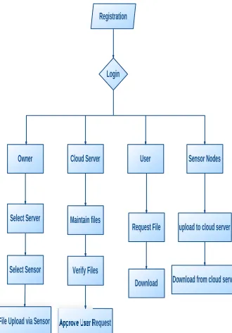
Registration
Login
Owner Cloud Server User Sensor Nodes
Select Server
Select Sensor
Approve User Request Verify Files Maintain files
File Upload via Sensor
Request File
Download
upload to cloud server
Download from cloud server
Figure 5: Data Flow Diagram UML DIAGRAMS
UML stands for Unified Modeling Language. UML is a standardized general-purpose modeling language in the field of object-oriented software engineering. The standard is managed, and was created by, the Object Management Group.
The goal is for UML to become a common language for creating models of object oriented computer software. In its current form UML is comprised of two major components: a Meta-model and a notation. In the future, some form of method or process may also be added to; or associated with, UML. The Unified Modeling Language is a standard language for specifying, Visualization, Constructing and documenting the artifacts of software system, as well as for business modeling and other non-software systems.
The UML represents a collection of best engineering practices that have proven successful in the modeling of large and complex systems.
The UML is a very important part of developing objects oriented software and the software development process. The UML uses mostly graphical notations to express the design of software projects.
GOALS:
The Primary goals in the design of the UML are as follows:
1. Provide users a ready-to-use, expressive visual modeling Language so that they can develop and exchange meaningful models.
2. Provide extendibility and specialization mechanisms to extend the core concepts. 3. Be independent of particular programming
languages and development process.
4. Provide a formal basis for understanding the modeling language.
5. Encourage the growth of OO tools market. 6. Support higher level development concepts
such as collaborations, frameworks, patterns and components.
7. Integrate best practices.
USE CASE DIAGRAM:
Conference Chair: Prof.Dr.G.ManojSomeswar, Director General, Global Research Academy, Hyderabad, Telangana, User
Registration
Owner
Cloud Server
Sensor Nodes
Select Server
Select Sensor
File Upload via Sensor
Upload to Cloud Server
Verify Files
Request File
Approve Request Download File Download from CloudServer
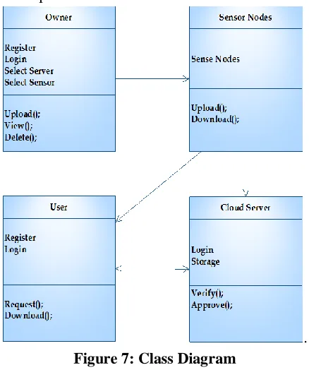
Figure 6 : Use Case Diagram CLASS DIAGRAM:
In software engineering, a class diagram in the Unified Modeling Language (UML) is a type of static structure
diagram that describes the structure of a system by showing the system's classes, their attributes, operations (or methods), and the relationships among the classes. It
explains which class contains information
.
Figure 7: Class Diagram SEQUENCE DIAGRAM:
A sequence diagram in Unified Modeling Language (UML) is a kind of interaction diagram that shows how processes operate with one another and in what order. It is a construct of a Message Sequence Chart. Sequence
diagrams are sometimes called event diagrams, event scenarios, and timing diagrams.
OWNER USER
Registration
CLOUD SERVER SENSOR NODES
Registration Select Server
Select Sensor File upload via Sensor
Upload to Cloud Server
Verify Files Request File
Approve User Request
Download
Download
Figure 8: Sequence Diagram ACTIVITY DIAGRAM:
Activity diagrams are graphical representations of workflows of stepwise activities and actions with support for choice, iteration and concurrency. In the Unified Modeling Language, activity diagrams can be used to describe the business and operational step-by-step workflows of components in a system. An activity diagram shows the overall flow of control.
A
Login
User Owner
Select Server
A
Cloud Server Sensor Nodes
Select Sensor
File Upload via Sensor
Maintain Files
Verify Files
Approve User Requests
Upload to Cloud Server
Download from Cloud server
Request File
Download
Figure 9: Activity Diagram INPUT DESIGN
Conference Chair: Prof.Dr.G.ManojSomeswar, Director General, Global Research Academy, Hyderabad, Telangana, usable form for processing can be achieved by
inspecting the computer to read data from a written or printed document or it can occur by having people keying the data directly into the system. The design of input focuses on controlling the amount of input required, controlling the errors, avoiding delay, avoiding extra steps and keeping the process simple. The input is designed in such a way so that it provides security and ease of use with retaining the privacy. Input Design considered the following things:
What data should be given as input?
How the data should be arranged or coded?
The dialog to guide the operating personnel in providing input.
Methods for preparing input validations and steps to follow when error occur.
OBJECTIVES
1. Input Design is the process of converting a user-oriented description of the input into a computer-based system. This design is important to avoid errors in the data input process and show the correct direction to the management for getting correct information from the computerized system.
2.It is achieved by creating user-friendly screens for the data entry to handle large volume of data. The goal of designing input is to make data entry easier and to be free from errors. The data entry screen is designed in such a way that all the data manipulates can be performed. It also provides record viewing facilities. 3. When the data is entered it will check for its validity. Data can be entered with the help of screens. Appropriate messages are provided as when needed so that the user will not be in maize of instant. Thus the objective of input design is to create an input layout that is easy to follow
OUTPUT DESIGN
A quality output is one, which meets the requirements of the end user and presents the information clearly. In any system results of processing are communicated to the users and to other system through outputs. In output design it is determined how the information is to be displaced for immediate need and also the hard copy
output. It is the most important and direct source information to the user. Efficient and intelligent output design improves the system’s relationship to help user decision-making.
1. Designing computer output should proceed in an organized, well thought out manner; the right output must be developed while ensuring that each output element is designed so that people will find the system can use easily and effectively. When analysis design computer output, they should Identify the specific output that is needed to meet the requirements.
2. Select methods for presenting information.
3. Create document, report, or other formats that contain information produced by the system.
The output form of an information system should accomplish one or more of the following objectives.
Convey information about past activities, current status or projections of the
Future.
Signal important events, opportunities, problems, or warnings.
Trigger an action.
Confirm an action.
SYSTEM ANALYSIS EXISTING SYSTEM:
Conference Chair: Prof.Dr.G.ManojSomeswar, Director General, Global Research Academy, Hyderabad, Telangana,
DISADVANTAGES OF EXISTING SYSTEM:
Those techniques often require special trusted hardware or secure kernel support.
Which makes them difficult to be
deployed on large-scale cloud
computing infrastructures.
PROPOSED SYSTEM:
In this paper, we present IntTest, a new integrated service integrity attestation framework for multitenant cloud systems. IntTest provides a practical service integrity attestation scheme that does not assume trusted entities on third-party service provisioning sites or require application modifications. IntTest builds upon our previous work RunTest and AdapTest but can provide stronger malicious attacker pinpointing power than RunTest and AdapTest. Specifically, both RunText and AdapTest as well as traditional majority voting schemes need to assume that benign service providers take majority in every service function. However, in large-scale multitenant cloud systems, multiple malicious attackers may launch colluding attacks on certain targeted service functions to invalidate the assumption. To address the challenge, IntTest takes a holistic approach by systematically examining both consistency and inconsistency relationships among different service providers within the entire cloud system. IntTest examines both per-function consistency graphs and the global.
ADVANTAGES OF PROPOSED SYSTEM:
A scalable and efficient distributed service integrity attestation framework for large scale cloud computing infrastructures.
A novel integrated service integrity attestation scheme that can achieve higher pinpointing accuracy than previous techniques.
A result auto correction technique that can automatically correct the corrupted results produced by malicious attackers.
Both analytical study and experimental evaluation to quantify the accuracy and
overhead of the integrated service integrity attestation scheme.
SYSTEM TESTING
The purpose of testing is to discover errors. Testing is the process of trying to discover every conceivable fault or weakness in a work product. It provides a way to check the functionality of components, sub assemblies, assemblies and/or a finished product It is the process of exercising software with the intent of ensuring that the
Software system meets its requirements and user expectations and does not fail in an unacceptable manner. There are various types of test. Each test type addresses a specific testing requirement.
TYPES OF TESTS Unit testing
Unit testing involves the design of test cases that validate that the internal program logic is functioning properly, and that program inputs produce valid outputs. All decision branches and internal code flow should be validated. It is the testing of individual software units of the application .it is done after the completion of an individual unit before integration. This is a structural testing, that relies on knowledge of its construction and is invasive. Unit tests perform basic tests at component level and test a specific business process, application, and/or system configuration. Unit tests ensure that each unique path of a business process performs accurately to the documented specifications and contains clearly defined inputs and expected results.
Integration testing
Conference Chair: Prof.Dr.G.ManojSomeswar, Director General, Global Research Academy, Hyderabad, Telangana,
Functional test
Functional tests provide systematic demonstrations that functions tested are available as specified by the
business and technical requirements, system
documentation, and user manuals.
Functional testing is centered on the following items: Valid Input : identified classes of valid input must be accepted.
Invalid Input : identified classes of invalid input must be rejected.
Functions : identified functions must be exercised.
Output : identified classes of application outputs must be exercised.
Systems/Procedures: interfacing systems or procedures must be invoked.
Organization and preparation of functional tests is focused on requirements, key functions, or special test cases. In addition, systematic coverage pertaining to identify Business process flows; data fields, predefined processes, and successive processes must be considered for testing. Before functional testing is complete, additional tests are identified and the effective value of current tests is determined.
System Test
System testing ensures that the entire integrated software system meets requirements. It tests a configuration to ensure known and predictable results. An example of system testing is the configuration oriented system integration test. System testing is based on process descriptions and flows, emphasizing pre-driven process links and integration points.
White Box Testing
White Box Testing is a testing in which in which the software tester has knowledge of the inner workings, structure and language of the software, or at least its purpose. It is purpose. It is used to test areas that cannot be reached from a black box level.
Black Box Testing
Black Box Testing is testing the software without any knowledge of the inner workings, structure or language of the module being tested. Black box tests, as
most other kinds of tests, must be written from a definitive source document, such as specification or requirements document, such as specification or requirements document. It is a testing in which the software under test is treated, as a black box .you cannot “see” into it. The test provides inputs and responds to outputs without considering how the software works.
Unit Testing:
Unit testing is usually conducted as part of a combined code and unit test phase of the software lifecycle, although it is not uncommon for coding and unit testing to be conducted as two distinct phases.
Test strategy and approach
Field testing will be performed manually and functional tests will be written in detail.
Test objectives
All field entries must work properly.
Pages must be activated from the identified link.
The entry screen, messages and responses must not be delayed.
Features to be tested
Verify that the entries are of the correct format No duplicate entries should be allowed
All links should take the user to the correct page.
Integration Testing
Software integration testing is the incremental integration testing of two or more integrated software components on a single platform to produce failures caused by interface defects.
The task of the integration test is to check that components or software applications, e.g. components in a software system or – one step up – software applications at the company level – interact without error.
Test Results: All the test cases mentioned above passed successfully. No defects encountered.
Acceptance Testing
Conference Chair: Prof.Dr.G.ManojSomeswar, Director General, Global Research Academy, Hyderabad, Telangana, end user. It also ensures that the system meets the
functional requirements.
Test Results: All the test cases mentioned above passed successfully. No defects encountered.
IMPLEMENTATION MODULES:
1. Baseline Attestation 2. Integrated Attestation
a. Consistency graph analysis b. Inconsistency graph analysis 3. Auto-correction For Attacks
MODULES DESCRIPTION: Baseline Attestation:
Our approach is that if two service providers disagree with each other on the processing result of the same input, at least one of them should be malicious. Note that we do not send an input data item and its duplicates (i.e., attestation data) concurrently. Instead, we replay the attestation data on different service providers after receiving the processing result of the original data. Thus, the malicious attackers cannot avoid the risk of being detected when they produce false results on the original data. Although the replay scheme may cause delay in an ingle tuple processing, we can overlap the attestation and normal processing of consecutive tuples in the data stream to hide the attestation delay from the user. If two service providers always give consistent output results on all input data, there exists consistency relation-ship between them. Otherwise, if they give different outputs on at least one input data, there is inconsistency relationship between them. We do not limit the consistency relationship to equality function since two benign services providers may produce similar but not exactly the same results.
Integrated Attestation:
A. Consistency graph analysis: We first examine per-function consistency graphs to pinpoint suspicious service providers. The consistency links in per-function consistency graphs can tell which set of service providers keep consistent with each other on a specific service function.
Given any service function, since benign service providers always keep consistent with each other, benign service providers will form a clique in terms of consistency links. However, strategically colluding attackers can try to take majority in a specific service function to escape the detection. Thus, it is insufficient to examine the per-function consistency graph only. We need to integrate the consistency graph analysis with the inconsistency graph analysis to achieve more robust integrity attestation. B. Inconsistency graph analysis: Given an
inconsistency graph containing only the inconsistency links, there may exist different possible combinations of the benign node set and the malicious node set. However, if we assume that the total number of malicious service providers in the whole system is no more than K, we can pinpoint a subset of truly malicious service providers. Intuitively, given two service providers connected by an inconsistency link, we can say that at least one of them is malicious since any two benign service providers should always agree with each other. Thus, we can derive the lower bound about the number of malicious service providers by examining the minimum vertex cover of the inconsistency graph. The minimum vertex cover of a graph is a minimum set of vertices such that each edge of the graph is incident to at least one vertex in the set.
Auto correction For Attacks:
Conference Chair: Prof.Dr.G.ManojSomeswar, Director General, Global Research Academy, Hyderabad, Telangana,
RESULTS &CONCLUSION
In this research paper, we have presented the design and implementation of IntTest, a novel integrated service integrity attestation framework for multitenant software-as-a-service cloud systems. IntTest employs randomized replay-based consistency check to verify the integrity of distributed service components without imposing high overhead to the cloud infrastructure. IntTest performs integrated analysis over both consistency and inconsistency attestation graphs to pinpoint colluding attackers more efficiently than existing techniques. Furthermore, IntTest provides result autocorrection to automatically correct compromised results to improve the result quality. We have implemented IntTest and tested it on a commercial data stream processing platform running inside a production virtualized cloud computing infrastructure. Our experimental results show that IntTest can achieve higher pinpointing accuracy than existing alternative schemes. IntTest is lightweight, which imposes low-performance impact to the data processing
services running inside the cloud computing infrastructure.
REFERENCES
[1] Amazon Web Services, http://aws.amazon.com/, 2013.
[2] Google App Engine, http://code.google.com/appengine/, 2013.
[3] Software as a Service, http://en.wikipedia.org/wiki/Software as a Service, 2013.
[4] G. Alonso, F. Casati, H. Kuno, and V. Machiraju, Web Services Concepts, Architectures and Applications (Data-Centric Systems and Applications). Addison-Wesley Professional, 2002.
[5] T. Erl, Service-Oriented Architecture (SOA): Concepts, Technology, and Design. Prentice Hall, 2005.
[6] T.S. Group, “STREAM: The Stanford Stream Data Manager,” IEEE Data Eng. Bull., vol. 26, no. 1, pp. 19-26, Mar. 2003.
[7] D.J. Abadi et al., “The Design of the Borealis Stream Processing Engine,” Proc. Second Biennial Conf. Innovative Data Systems Research (CIDR ’05), 2005.
[8] B. Gedik et al., “SPADE: The System S Declarative Stream Processing Engine,” Proc. ACM SIGMOD Int’l Conf. Management of Data (SIGMOD ’08), Apr. 2008.
[9] S. Berger et al., “TVDc: Managing Security in the Trusted Virtual Datacenter,” ACM SIGOPS Operating Systems Rev., vol. 42, no. 1, pp. 40-47, 2008.
[10] T. Ristenpart, E. Tromer, H. Shacham, and S. Savage, “Hey, You Get Off My Cloud! Exploring Information Leakage in Third-Party Compute Clouds,” Proc. 16th ACM Conf. Computer and Communications Security (CCS), 2009.
[11] W. Xu, V.N. Venkatakrishnan, R. Sekar, and I.V. Ramakrishnan, “A Framework for Building Privacy-Conscious Composite Web Services,” Proc. IEEE Int’l Conf. Web Services, pp. 655-662, Sept. 2006.
[12] P.C.K. Hung, E. Ferrari, and B. Carminati, “Towards Standardized Web Services Privacy Technologies,” IEEE Int’l Conf. Web Services, pp. 174-183, June 2004.
[13] L. Alchaal, V. Roca, and M. Habert, “Managing and Securing Web Services with VPNs,” Proc. IEEE Int’l Conf. Web Services, pp. 236- 243, June 2004.
[14] H. Zhang, M. Savoie, S. Campbell, S. Figuerola, G. von Bochmann, and B.S. Arnaud, “Service-Oriented Virtual Private Networks for Grid Applications,” Proc. IEEE Int’l Conf. Web Services, pp. 944-951, July 2007.