ADMINISTRATOR’S GUIDE
AXXESS
Part No. 550.8001 Issue 5.1, March 2000
AXX
ESS
OR
Y T
A
LK V
OICE MAIL
S
YSTE
M
ADMINISTRA
T
OR FE
A
T
URES
T
O RE CO RD A BRO AD CAS T ME SSA GE — C all t h e V oice Mail extens
ion num ber . — P res s , t h en ent er t h e Sy st em A d mi ni st rat o r m ai lb ox num ber an d p ass -wo rd . — P re ss , th en p re ss . — R ecord yo ur m es sage. — W hen yo
u have co
mpl et ed yo ur mes sag e, h ang u p O R pres s for mo re o p ti ons .
T
O PER F O R M MA ILB O X M A IN TE NAN CE:
— C all t h e V oice Mail extens
ion num ber . — P res s , t h en ent er t h e Sy st em A d mi ni st rat o r m ai lb ox num ber an d p ass -wo rd . — P re ss , th en p re ss . — D ial th e m ailb o x , ex ten si o n I D , o r g ro u p lis t n u m b er to b e p ro g ra m m ed . P ro g ram th e per so n al op ti o n s, fo ll o w in g t h e pro m pt s, as us ual .
T
O IMP O R T A FA X D O CUME N T:
— U si ng a fax m achine, cal l th e V oice Mail extens
ion . — P res s an d then
enter the Sy
st em Adm in is trato r mailbox nu mber an d pa ss w o rd . — P re ss , th en p re ss . — E n
ter the f
ax d o cume nt nu mber . If t h e do cum ent num b er d o es no t al re ady exi st , pres s if th e nu mber is co rrect OR pres s and re-r enter the num ber . If t h e do cu m ent n u m be r a lr ead y ex is ts , Pres s to re place the docu m ent OR pres s to en te r ano ther n u mb er . If t h e do cu m ent i s b ei n g s ent , up da te d , or d el et ed , th at n u mb er cann o t be u sed ri gh t now . Ent er a new n u mb er or han g up . If you d id n o t ent er a va li d nu m b er , en te
r a new n
u mb er . — W hen prom pt ed, pres s ST A R T on you r fax machi n e. — W h en t h e f ax tr an sm iss io n is co m p lete, p res s t o co n ti n u e im p o rtin g d o c-u m en ts, o r p ress to ex it .
Q
UI
CK
R
EFERENCE
G
UI
DE
T
O
AXXESS A
ND
AXXESSOR
Y
T
AL
K
S
YSTEM
A
D
M
IN
IS
T
R
AT
OR
F
EAT
URES
Th es e a re t h e basic in st ru ctio n s f o r th e m o st f re q u en tly u sed A XXESS Adm in ist rat o r and AXX E S S O R Y T a lk S y st em Admi n ist rat o r feat ur d etailed i n fo rm atio n o n th es e f eatu res, r ef er to th e Ad min istr a to r’ s Gu id e .AXX
ESS
SYS
TEM
ADMINISTRA
T
OR FEA
T
U
R
E
S
T
O PL A C E THE SY ST EM IN NI G H T OR DA Y MO DE:
— Wh il e on hoo k, en te r .T
O PL A C E A SI NGL E NO DE IN DA Y OR N IGH T MO DE:
— Wh il e on hoo k, ent er (Enab le N et w o rk Ni g h t Mode) OR(
En ab le Netwo rk Da y Mo de). T h en enter the d
es ired nu mber .
T
O SET SY ST EM OR NE TWO R K DAT E AN D TI ME:
— Wh il e on ho ok , ent er ( Sy st em Dat e/T im e) o r en ter(
Netwo rk Date/T im e) . — Us e t h e keyp ad key s toenter the mo
nth, d
ay
, and y
ear
. (For ex
ample, p 01 03 00 fo r J anuar y 3, 2 0 0 0 .) OR p res s to s k ip ah ead wit h ou t ch th e d ate. — U se th e key p ad key s t o ent er t h e t im e in ho urs and mi nu te s. (F or exam ent er 090 0 f o r 9 :00. ) OR p res s twice to ex it wi th o u t ch an g in g th e — If th e sys
tem is s
et fo r 1 2 -h o u r d isp la y fo rm a t, p res s fo
r AM or p
fo r P M .
T
O S Y NCHR O N IZ E NE TWO R K TIME:
Wh il e on hoo k, en te r .T
O RE SPO ND TO AN ALA R M ME SS AG E:
— W h en a minor alarm ind icati o n ap pears, write d
o
wn th
e alarm in
form — W h ile o n ho ok, clear th e alar m by en te ri ng
(
C lear Sys Alarm) or entering(
C lear Network Alarm). — Lo ok u pthe alarm in
t h e Adminis trator ’s Guide an
d take the ap
T
O PR OGR A M SY ST EM S PEE D DI AL NU M B E R S:
— W h il e on hoo k, ent er . — En ter th e sp eed -d ial lo catio n co d e ( 0 0 0 -9 9 9 ). — T o ch ange or pr
ogr am th e n a m e: En ter th e d es ir ed n am e fo r th e s p ee d -di al nu m b er : In num eri c m ode, t h e k e yp a d k e ys a re us e d t o ent e r numb e rs 0-9, t h e ke y i s us ed f o r en te ri ng a h yph e n , a n d t h e k ey i s u se d fo r e n te ri ng a co lo n. In al phanum eri c m ode, keypa d ke ys are used to ent er th e desi red le tt ers, nu mbers, a n d pun c tuat
ion. The nu
mber of t
im
es a key i
s press e d det e r-mi nes w h ic h char act e r is ent er ed. W h en adj o in ing cha rac te rs a re loc at ed un der t h e s a me key , pres s t o adv a n c
e to the next
AXXESS
Issue 5.1, March 2000
©Inter-Tel Integrated Systems, Inc. 2000 printed in USA
This Inter-Tel AXXESS Administrator’s Guide is released by INTER-TEL INTEGRATED SYSTEMS, INC. as a guide for AXXESS System and AXXESSORY Talk Voice Mail administrators. It provides information necessary to properly administer the system.
The contents of this manual, which reflect current INTER-TEL standards and which document software versions 827.8915-8919, are subject to revision or change without notice. Software packages released after the publication of this manual will be documented in addenda to the manual or succeeding issues of the manual.
For additional information and/or technical assistance, certified technicians may contact:
Customer Support Department INTER-TEL INTEGRATED SYSTEMS, INC.
7300 West Boston Street Chandler, AZ 85226-3224
(480) 961-9000 (during normal business hours) (480) 961-0277 (after hours or on weekends)
If you have any questions or comments regarding this manual or
other technical documentation, contact
Inter-Tel’s Technical Publications Department at:
[email protected]
Inter-Tel® is a registered trademark of Inter-Tel, Incorporated.
Inter-Tel Integrated Systems™ is a trademark of Inter-Tel Integrated Systems, Inc.
Inter-Tel AXXESS™ and Inter-Tel AXXESSORY Talk™are trademarks of Inter-Tel Integrated Systems, Inc. IBM® and OS/2® Warp are registered trademarks of International Business Machines Corporation. MS-DOS® and Microsoft® Windows® are registered trademarks of Microsoft Corporation. MOD-TAP® is a registered trademark of Mod-Tap System.
Page v
CONTENTS
PAGE
Table Of Contents . . . v
FCC Regulations . . . .xi
Safety Regulations . . . .xiv
Introduction . . . 1
The AXXESS Telephone System
1
AXXESS Networks . . . 1
AXXESS System Administrator Duties . . . 2
AXXESSORY Talk . . . 3
AXXESSORY Talk Voice Mail Networks . . . 4
AXXESSORY Talk Voice Mail Administrator Duties. . . 4
Administrator Procedures . . . 5
AXXESS System Administrator Features . . . 6
Placing The System In Night Mode . . . 6
Placing Nodes In Day Or Night Mode . . . 6
Setting System Date And Time . . . 7
Setting Network Date And Time . . . 7
Synchronize Network Time . . . 8
Database Programming . . . 9
Programming System Speed Dial Numbers . . . 26
System And Network Alarm Reporting . . . 28
Freezing/Unfreezing The System History . . . 30
Freezing/Unfreezing The Network History . . . 30
Seizing A Device . . . 31
AXXESSORY Talk Voice Mail System Administrator Features . . . 32
Broadcast Messages . . . 32
Mailbox/Group List Maintenance . . . 33
Importing Fax Documents . . . 34
Custom Audiotex Recordings. . . 35
AXXESS System Hardware . . . 53
Introduction 53
Station Instruments . . . 54
Keysets . . . 54
Agent Set . . . 71
Single-Line Sets . . . 72
Digital Direct Station Selection/Busy Lamp Field (DSS/BLF) Units . . . 73
Page vi
CONTENTS
PAGE
AXXESS System Features . . . 77
Introduction 77
Access To The Features . . . 78
Feature Keys . . . 78
Special Key And Hookflash . . . 78
Feature Codes . . . 79
Attendant Stations . . . 88
Network And Local Primary Attendants . . . 88
Attendant Recall . . . 88
Hunt Groups . . . 90
Hunt Group Call Distribution. . . 90
Hunt Group Call Processing . . . 91
Hunt Groups And Call Forwarding . . . 91
Hunt Group Remove/Replace And Do-Not-Disturb . . . 92
UCD Hunt Groups . . . 93
ACD Hunt Groups . . . 97
Trunk Features . . . 101
Caller ID, DNIS, And ANI. . . 101
Outgoing-Access, Allowed- Answer, And Ring-In Assignments . . . 104
Automatic Route Selection (ARS) . . . 105
Toll Restriction . . . 107
Emergency Call Feature . . . 110
Day And Night Modes . . . 111
Direct Inward System Access (DISA) . . . 111
Keyset Features . . . 113
Volume Controls . . . 113
Selectable Ring Tone . . . 114
Extension Number, Username, Time and Date Display. . . 114
“All Transient Displays” Station Flag . . . 114
“DKTS Alternate Transient Display Timer” Station Flag And Timer . . . 115
“Transient Call Indication On Call Answer” Station Flag . . . 115
Using DSS/BLF Keys (DSS/BLF Unit Or Keyset DSS/BLF). . . 115
User-Programmable Feature Keys . . . 117
Standard/Alternate Keymap Switching . . . 118
Automatic Call Access . . . 119
Music-On-Hold And Background Music . . . 120
Multilingual Capability . . . 121
Stations . . . 121
Trunks . . . 121
Do-Not-Disturb And Reminder Messages . . . 121
Page vii
CONTENTS
PAGE
Intercom Calls . . . 123
Programming For Private Intercom Calls. . . 123
Station-To-Station Calling . . . 124
Intercom Camp On And Queue Callback. . . 127
Inter-Station Messages . . . 129
Leaving Messages . . . 129
Responding To Messages . . . 131
Off-Hook Voice Announce (OHVA) . . . 133
Outside Calls . . . 135
Placing Outside Calls . . . 135
Receiving Outside Calls . . . 138
Keyset On-Hook Monitoring . . . 139
Keyset Group Listen Feature . . . 139
Trunk Camp On And Busy Trunk Callback (Queue) . . . 140
Account Codes . . . 141
Placing Calls On Hold . . . 144
Individual Hold. . . 144
System Hold (Keysets Only) . . . 145
Consultation Hold. . . 145
Hold Recall . . . 145
Microphone Mute . . . 146
Call Waiting . . . 147
Call Transfer . . . 149
Feature Codes . . . 149
Transferring Conference Calls . . . 149
Transfer To A System Forward . . . 149
Transfers And Outside Calls. . . 149
Transfer-To-Connect Station Flag . . . 149
Transfer To Ring. . . 150
Transfer To Hold. . . 151
Transfer Recalls . . . 151
Call Screening . . . 152
Reverse Transfer
153
Conference Calls . . . 154
Placing A Conference Call . . . 154
Add Parties To A Conference. . . 156
Exiting A Conference . . . 156
Record-A-Call . . . 159
Page viii
CONTENTS
PAGE
System Forwarding . . . 164
Individual Station Forwarding Points. . . 165
Hunt Group Forwarding Points . . . 166
Handsfree Announce System Forward Option. . . 166
Manual Call Forwarding And System Forwarding . . . 167
System Forward Enable/Disable . . . 168
Unanswered System Forward Calls . . . 169
Call Forwarding . . . 170
FWD Key . . . 171
Forward To An Outside Number . . . 171
Forward To The Message Center . . . 172
Forward To An Attendant. . . 172
Forward To Voice Mail. . . 172
How To Forward Calls To An Extension Or Outside Number. . . 172
Speed Dialing . . . 174
System Speed Dialing. . . 174
Station Speed Dialing . . . 176
Intercom, Speed-Dial, And Feature Code Directory (Keysets Only) . . . 181
House Phone . . . 184
Redialing . . . 186
Using The Last Number Saved Feature . . . 187
Using The Last Number Dialed Feature. . . 187
Paging . . . 188
Remove From Paging
188
Do-Not-Disturb . . . 189
Do-Not-Disturb Override . . . 192
Remote Feature Programming . . . 193
Station Password . . . 193
Remote Do-Not-Disturb Programming . . . 194
Remote Forward Programming . . . 196
Default Station . . . 197
Hookflash 197
Reminder Messages (Keysets Only) . . . 198
Record Keeping And Maintenance Features . . . 200
Call Cost Accounting . . . 200
Page ix
CONTENTS
PAGE
AXXESSORY Talk Features . . . 205
Introduction 205
Automated Attendant . . . 206
Automated Attendant Applications . . . 207
Automated Attendant Recall Destination . . . 207
Automated Attendant Custom Audiotex Recordings . . . 207
Extension IDs . . . 208
Call Routing Announcement . . . 209
Call Routing Custom Audiotex Recordings . . . 209
Call Screening . . . 210
Digit Translation. . . 210
Digit Translation Nodes . . . 210
AXXESSORY Talk Fax On Demand. . . 212
Directories . . . 214
Locating A Name . . . 215
Changing The First/Last Name Search. . . 215
Listening To The Next/Previous Name . . . 215
Accepting A Name . . . 216
Requesting Additional Information . . . 216
Using The Directories. . . 216
Record-A-Call . . . 217
Scheduled Time-Based Application Router (STAR) . . . 218
SMDR Information Storage And Retrieval . . . 219
Voice Mail . . . 220
Voice Mail And Message Notification/Retrieval Applications . . . 220
Mailboxes . . . 221
Group Lists . . . 222
Message Notification To Stations. . . 223
Cascading Remote Message Notification. . . 223
Using Voice Mail . . . 226
Access To A Mailbox . . . 226
Initializing A Mailbox or Extension ID . . . 226
Listening To Messages . . . 227
Recovering Deleted Messages . . . 229
Sending A Message . . . 230
Canceling Unheard Messages. . . 231
Personal Options. . . 232
Outside Caller Use Of Voice Mail . . . 235
AXXESSORY Talk Central Unified Messaging . . . 237
Outbound Fax . . . 238
Page x
CONTENTS
PAGE
Automatic Fax Detection . . . 240
AXXESSORY Talk Central Required . . . 240
Fax Card Required . . . 240
FAX E-Mail Message Format . . . 240
Multilingual Capability . . . 241
AXXESSORY Talk Networking . . . 242
Undeliverable Messages . . . 242
Examples . . . 243
Page xi
FCC Regulations
IMPORTANT:
(1) This equipment complies with Part 68 of FCC rules. On the side of the KSU is a label that contains, among other information, the FCC registration number and ringer equiva-lence number (REN) for this equipment. Customers connecting this equipment to the telephone network shall, before such connection is made, give notice to the telephone company of the particular line(s) to which such connection is to be made, and shall pro-vide the telephone company with the following information:
— Complies with Part 68 of FCC rules
— FCC registration number: BE2USA-64572- MF-E (for MF-rated systems), BE2USA- 64573-KF-E (for KF-rated systems), or BE2USA-24359-PF-E (for PBX systems)
— USOC numbers of required interface jacks (see chart on next page)
— Service order code (SOC), as applicable (see chart on next page)
— Facility interface code (FIC) (see chart on next page)
— Ringer equivalence number (REN), as applicable (see chart on next page)
NOTE The REN is used to determine the quantity of devices which may be con-nected to the telephone line. Excessive RENs on the telephone line may result in the devices not ringing in response to an incoming call. In most, but not all areas, the sum of the RENs should not exceed five (5.0). To be certain of the number of devices that may be connected to the line, as determined by the total RENs, contact the telephone company to determine the maximum REN for the calling area.
The telephone company should also be given notice upon final disconnection of this equipment from the particular line(s).
It is also the responsibility of the customer to provide the telephone company with reg-istration numbers of any other devices which are configured for connection to the tele-phone network.
(2) This equipment cannot be used on public coin service provided by the telephone com-pany. Connection to party line service is subject to state tariffs. (Contact the state public utility commission, public service commission, or corporation commission for informa-tion.)
(3) If this equipment causes harm to the telephone network, the telephone company will notify the customer in advance that service may be temporarily discontinued. But if advance notice is not practical, the telephone company will notify the customer as soon as possible. Also, the customer will be advised of the right to file a complaint with the FCC, if necessary.
Page xii
(5) If trouble is experienced with this equipment, contact a local authorized factory service representative for repairs and/or warranty information. The customer, users, and unau-thorized technicians should not repair, make adjustments to, or attempt to service this equipment in any way.
(6) In the event of trouble with the telephone line(s), this equipment must be disconnected from the telephone line(s). If trouble ceases, the equipment must be repaired by an authorized factory service representative. If the trouble continues to occur with the equipment disconnected, the telephone company should be notified that they have a problem. If this is the case, repairs or adjustments made by the telephone company will be made at their expense.
(7) Allowing this equipment to be operated in such a manner as to not provide proper answer supervision signaling is in violation of Part 68 of FCC rules. This equipment returns answer supervision signals to the public telephone network when: answered by the called station, answered by the attendant, routed to a recorded announcement that can be administered by the equipment user, and routed to a dial prompt. This equipment also returns answer supervision on all DID calls forwarded back to the public telephone network. Permissible exceptions are: a call is unanswered, busy tone is received, and reorder tone is received.
(8) This equipment is capable of providing users access to interstate providers of operator services through the use of equal access codes. Failure to provide equal access capabili-ties is a violation of the Telephone Operator Consumer Services Improvement Act of 1990 and Part 68 of the FCC Rules
TYPE OF PORT INTERFACE
FACILITY INTERFACE CODE (FIC)
RINGER EQUIV ALENCE NO. (REN)
SERVICE ORDER CODE (SOC)
USOC JACK CONNECTOR
2-Wire Loop 02LS2 0.6B
–
RJ21X2-Wire Loop/Ground 02LS2/02GS2 3.6B/4.4B
–
RJ21X2-Wire Ground 02GS2 0.6B
–
RJ21XOPX Class C* 0L13C
–
9.0F RJ11C, RJ21X2-Wire DID** 02RV2-T 0.0B AS.2 RJ11C, RJ21X
D4 Superframe/AMI 04DU9-BN
–
6.0Y RJ48CD4 Superframe with B8ZS
04DU9-DN
–
6.0Y RJ48CExtended Super frame (ESF)
04DU9-1KN
–
6.0Y RJ48CESF with B8ZS 04DU9-1SN
–
6.0Y RJ48CPrimary Rate ISDN 04DU9-1SN
–
6.0Y RJ48C* Also interfaces with Class A and B.
** When using T1 facilities to provide DID service, do not use the DID facility interface code (FIC); instead, pro-vide the telephone company with DID answer supervision code "AS.2" and the FIC for the requested T1 service.
NOTICE
NOTICE
Page xiii
WARNING This equipment generates and uses radio frequency energy and if not installed and used properly, that is, in strict accordance with the manufacturer’s instructions, may cause interference to radio and television reception. It has been type tested and found to comply with the limits for a Class A computing device in accordance with the specifications in Subpart J of Part 15 of FCC Rule. Operation of this equipment in a residential area may cause unacceptable interference to radio and TV reception requiring the operator to take whatever steps are neces-sary to correct the interference. However, there is no guarantee that interference will not occur in a particular installation. If this equipment does cause interference to radio or television reception, which can be determined by turning the equipment off and on, the user is encour-aged to try to correct the interference by one or more of the following measures:
• Reorient the receiving antenna
• Relocate the KSU with respect to the receiver
• Check that the KSU and receiver are not on the same circuit; the KSU must be powered from an isolated, dedicated AC outlet
If necessary, the user should consult the dealer or an experienced radio/television tech-nician for additional suggestions. The user may find the following booklet prepared by the FCC helpful: "How to Identify and Resolve Radio-TV Interference Problems"
This booklet is available from the U.S. Government Printing Office, Washington, D.C. 20402, Stock No. 004-000-00398-5.
If RFI problems persist, contact Inter-Tel Customer Support.
Page xiv
Safety Regulations
IMPORTANT SAFETY INSTRUCTIONS
The following safety information is reprinted from UL 1459. When using your telephone equipment, basic safety precautions should always be followed to reduce the risk of fire, elec-tric shock, and injury to persons, including the following:
1. Read and understand all instructions.
2. Follow all warnings and instructions marked on the product.
3. Unplug this product from the wall outlet before cleaning. Do not use liquid cleaners or aerosol cleaners. Use a damp cloth for cleaning.
4. Do not use this product near water (for example, in a wet basement).
5. Do not place this product on an unstable cart, stand, or table. The product may fall, causing serious damage to the product.
6. Slots and openings in the cabinet and the back or bottom are provided for ventilation, to protect it from overheating; these openings must not be blocked or covered. This prod-uct should never be placed near or over a radiator or heat register. This prodprod-uct should not be placed in a built-in installation unless proper ventilation is provided.
7. This product should be operated only from the type of power source indicated in the manual. If you are not sure of the type of power source to your building, consult your dealer or local power company.
8. This product is equipped with a three-wire grounding type plug, a plug having a third (grounding) pin. This plug will only fit into a grounding type power outlet. This is a safety feature. If you are unable to insert the plug into the outlet, contact your electri-cian to replace your obsolete outlet. Do not defeat the safety purpose of the grounding type plug.
9. Do not allow anything to rest on the power cord. Do not locate this product where the cord will be abused by persons walking on it.
10. Do not use an extension cord with this product’s AC power cord. The AC outlet for this product should not be used for any other electrical equipment.
11. Never push objects of any kind into this product through cabinet slots as they may touch dangerous voltage points or short out parts that could result in a risk of fire or electric shock. Never spill liquid of any kind on the product.
12. To reduce the risk of electric shock, do not disassemble this product, but take it to a qualified serviceman when some service or repair work is required. Opening or remov-ing covers may expose you to dangerous voltages or other risks. Incorrect reassembly can cause electric shock when the product is subsequently used.
Page xv 13. Unplug this product from the wall outlet and refer servicing to qualified service
person-nel under the following conditions:
a. When the power supply cord or plug is damaged or frayed. b. If liquid has been spilled into the product.
c. If the product has been exposed to rain or water.
d. If the product does not operate normally by following the operating instructions. Adjust only those controls that are covered by the operating instructions because improper adjustment of other controls may result in damage and will often require extensive work by a qualified technician to restore the product to normal operation.
e. If the product has been dropped or the cabinet has been damaged. f. If the product exhibits a distinct change in performance.
14. Avoid using a telephone (other than a cordless type) during an electrical storm. There may be a remote risk of electric shock from lightning.
15. Do not use the telephone to report a gas leak in the vicinity of the leak.
SAVE THESE INSTRUCTIONS
Page 1
The AXXESS Telephone System
Introduction
This Administrator’s Guide provides all the information an administrator should need about the AXXESS system hardware and features, and it gives detailed instructions on their use. Refer to the user guide provided with each phone for simplified instructions on using telephone and voice mail system features.
THE AXXESS TELEPHONE SYSTEM
The Inter-Tel AXXESS System is a state-of-the-art, digital, voice/data, hybrid telephone sys-tem. As a hybrid system, it incorporates many of the user-friendly features of key systems with many of the expanded features and flexibility of private branch exchange (PBX) systems.
The AXXESS System is designed to meet the needs of growing businesses. In fact, the sys-tem's unique digital signal processing (DSP) structure allows it to be easily adapted and expanded as business communication needs change, especially with the Caller ID, Automatic Number Identification (ANI), Dialed Number Identification Service (DNIS), and Integrated Services Digital Network (ISDN) features. The modular design makes the system easy to install and service. And, the programmable features provide an abundance of user-friendly applications to meet each customer's needs. Highlights of the system's design include:
• Advanced microprocessor technology.
• Modular, easily replaceable hardware with add-on capabilities for optional features.
• Flexible programming to customize many system and station features.
AXXESS NETWORKS
With AXXESS software version 5.0 (and higher), you can connect two or more AXXESS sys-tems to form a network that provides a seamless interface between the syssys-tems. To the user, the network appears as though it is one integrated system. With few exceptions, the user can per-form all of the functions across the network that he can within a single AXXESS system.
In this manual, all references to a “network” mean two or more connected AXXESS systems. Each AXXESS system in a network is called a “node.”
The maximum capacities of the AXXESS network are listed in the following table.
* The maximum number of stations and trunks that can be installed is limited by the number of voice channels and/or system memory resources available.
FEATURE/DEVICES CAPACITY
AXXESS System Nodes per network 63
Local devices per AXXESS node 512*
Off-node devices per AXXESS node 8000
Page 2 AXXESS System Administrator Duties
AXXESS SYSTEM ADMINISTRATOR DUTIES
As an AXXESS System Administrator you can provide the following services:
• Place the local phone system or other systems in the network in night mode or day mode
• Set the date and time of the local system
• Set the network date and time and re-synchronize clocks in the network. • Make database changes (see page 9 for a list of programming areas) • Program system speed-dial numbers on the local system
• Receive and clear displayed system and network alarms • Using diagnostic mode features:
— Freeze and unfreeze database history on the local system or other systems in the network
— Print error logs
— Seize specific devices for troubleshooting purposes
Administrator features are described in detail beginning on page 6.
Page 3
AXXESSORY Talk
AXXESSORY TALK
The Inter-Tel AXXESSORY Talk voice processing system can be used for any of the following applications:
• Voice Mail: This application handles all calls that are directed to voice mail (other than
through the Message Notification/Retrieval application) by subscribers and non-sub-scribers. Callers will hear the main company greeting, followed by a menu of available options. Stations can forward or transfer calls directly to their mailbox using this appli-cation’s.
• Directory Services: Directory services provide callers with a list of mailboxes and
extension IDs.
• Automated Attendant: The automated attendant is a programmable feature that can be
used to provide automated call answering service. Calls can transfer, forward, or directly ring in to an automated attendant. When an automated attendant answers a call, it plays a recording that gives dialing instructions. After hearing the recording (or at any time while it is playing), the caller may then dial an extension or mailbox number.
• Automated Attendant Recall Destination: If a call, that is transferred by the
auto-mated attendant, is not answered before the Transfer AXXESSORY Talk timer expires, the call recalls the Automated Attendant Recall Destination. The Recall Destination announces that the station is unavailable and allows the caller to leave a message (if the station has an associated mailbox) or dial another extension.
• Call Routing Announcement: Call Routing Announcements can be used two ways:
— A Call Routing Announcement application can be used in place of a playback device. The playback device function is especially useful for programming hunt group announcement and overflow stations. When called, the Call Routing Announcement application will play a recording and then hang up.
— The Call Routing Announcement application can use Digit Translation which allows the caller to press a single digit for access to a mailbox, a Fax On Demand function, or a station or hunt group that has an associated mailbox or extension ID. Digit translation can be programmed for each digit 0-9, #, and *, plus a Timeout that is used when the caller does not enter a digit. Each digit can lead to a “digit translation node” that has its own digit translation values. This layered Call Rout-ing Announcement digit translation creates a “tree” of programmable digit transla-tion nodes.
• Record-A-Call: This feature allows a station user to record an ongoing call in an
AXXESSORY Talk mailbox message. When a station user enters the Record-A-Call feature code, the system places a call to the station's assigned Record-A-Call applica-tion. When the application answers, the system sets up a conference call with the sta-tion's Record-A-Call mailbox. If programmed, the mailbox plays a greeting to indicate that the recording is in progress.
• STAR: The Scheduled Time-Based Application Router (STAR) enhances the
program-mability of the voice mail application greetings. With STAR, applications can be pro-grammed to play alternative greetings for holidays and weekends. A STAR application is a table of up to 20 entries, that serves as a “routing table” which tells the AXXES-SORY Talk which application will be used, based on day and time information in the table. (The applications are programmed to play the greetings, not the STAR applica-tion. The STAR routes the call to the right applicaapplica-tion.)
• Station Message Detail Recording (SMDR) Information Storage: SMDR
Page 4 AXXESSORY Talk Voice Mail Networks
AXXESSORY TALK VOICE MAIL NETWORKS
An AXXESSORY Talk Voice Mail unit can be installed on any or all nodes in the AXXESS network. These AXXESSORY Talk Units can also be networked together to allow a caller to leave a message on the local AXXESSORY Talk for a mailbox located on another AXXES-SORY Talk in the network.
The maximum capacities of the network are listed in the following table.
a This is the maximum number of nodes supported by the software. System traffic may limit
the actual number of nodes that can be supported without affecting system performance.
b This is the maximum number of mailboxes supported by the NT-based software. The
maxi-mum number of mailboxes on an OS/2 AXXESSORY Talk should be limited to 500 for opti-mum performance.
For more information on AXXESSORY Talk networks, see page 242.
AXXESSORY TALK VOICE MAIL ADMINISTRATOR DUTIES
As the voice mail System Administrator, you can use special features that are not provided to other voice mail users. The System Administrator mailbox has all standard subscriber features plus the ability to do the following:
• Record a broadcast message
• Perform mailbox and group list maintenance
• Create and select custom audiotex recordings (voice mail company greetings, auto attendant recordings, call routing announcements, and hunt group overflow and announcement station recordings)
• Import fax documents
• Customize voice mail prompts
Voice Mail System Administrator features are described in detail on page 32.
FEATURE/DEVICES CAPACITY
AXXESSORY Talk Units (nodes) per network 100a
Local or Off-Node Mailboxes and/or Extension IDs per AXXESSORY Talk node
2000b
Group Lists per node Members per group list
100 100
Page 5
Administrator Procedures
Any keyset can be designated as an AXXESS System Administrator and/or an AXXESSORY Talk Voice Mail System Administrator during database programming. All administrator sta-tions should be equipped with display keysets to show system alarms and to make program-ming easier.
This section gives you all instructions for using the Administrator Features of the AXXESS System and the AXXESSORY Talk.
• AXXESS System Administrator Features begin on the next page.
• AXXESSORY Talk Administrator Features begin on page 32.
A quick reference card is located in the front of this book for your convenience.
Page 6 AXXESS System Administrator Features
AXXESS SYSTEM ADMINISTRATOR FEATURES
Any display keyset station (attendant or non-attendant) can be assigned as a system administra-tor. Administrator stations provide the following services:
• Place the local node or other nodes in the network in night mode or day mode • Set the date and time of the local node
• Set the network date and time and re-synchronize clocks in the network. • Make database changes (see page 9 for a list of programming areas) • Program system speed-dial numbers on the local node
• Receive and clear displayed system and network alarms • Using diagnostic mode features:
— Freeze and unfreeze the database history for the local node or any node in the net-work using programmed freeze zones
— Print error logs
— Seize specific devices for troubleshooting purposes
Any keyset station can be programmed to be an Administrator station by the database pro-grammer or by another Administrator station.
If a non-Administrator station user attempts to use the Administrator features, the user will hear reorder tones and the display will show CANNOT ACCESS RESERVED FEATURE.
PLACING THE SYSTEM IN NIGHT MODE
An Administrator station can place the local node in day or night mode. The day/night mode determines which lists the system will use for trunk access, toll restriction, etc.
Night mode also affects the night transfer relays on the Options Card (OPC). The relays are activated when the system is placed in night mode.
TOTURNNIGHTMODEONOROFF:
While on hook, enter the Night Ring On/Off feature code (9860). You hear a single confirmation tone. The display shows NIGHT MODE IS ON (or OFF). Then, if night mode was turned on, the display shows THE SYSTEM IS IN NIGHT MODE until day mode is turned on.
PLACING NODES IN DAY OR NIGHT MODE
An Administrator station can place one or more nodes in day or night mode. The day/night mode determines which lists the system will use for trunk access, toll restriction, etc.
The network determines the day/night mode status of a call based on the day/night mode status of the node where the trunk resides.
TOTURNNIGHTMODEON:
(1) While on hook, enter the Enable Network Night feature code (9861). (2) You are prompted to enter a node number. Enter the desired node number.
(3) You hear a single confirmation tone. The display shows NIGHT MODE IS ON. Then the display shows NODE X IS IN NIGHT MODE until day mode is turned on.
TOTURNDAYMODEON:
Page 7
Setting System Date And Time
SETTING SYSTEM DATE AND TIME
Occasionally, the system time or date needs to be reset (for example, when the system is defaulted or for daylight-saving time). Any Administrator can change the date and time that appears on all display keysets and in the SMDR reports. The day of the week is automatically calculated and set by the system when the date is entered.
TOSETTHESYSTEMDATEANDTIME:
NOTE You may backspace to correct entries by pressing the MUTE key or you may press or CANCEL to leave it unchanged and start over.
(1) While on hook, enter the Set Date/Time feature code (9800). Your display shows DATE
(current date).
If you do not need to change the date, press or ACCEPT to skip to the TIME XX:XX prompt.
(2) Use the keypad keys to enter the month, day, and year. For example, press 010398 for January 3, 1998. When finished, the display shows TIME (current time). If you entered the date incorrectly, the display shows INVALID DATE and you are prompted to enter a new date. NOTE: If using a station programmed for Japanese, enter the date as year, month, date. For example, 980103 for January 3, 1998.
If you do not need to change the time, press or ACCEPT twice to exit. The display shows SYSTEM DATE AND TIME UPDATED.
(3) Use the keypad keys to enter the time in hours and minutes. (For example, enter 0900 for 9:00.) If you entered the time incorrectly, the display shows INVALID TIME and you are prompted to enter a new time.
(4) If the system is set for 12-hour display format, the display shows SELECT AM OR PM
(AM=1 PM=2). Press for AM (or the AM menu key) or press for PM (or the PM menu key). The display shows SYSTEM DATE AND TIME UPDATED. If you press any key other than 1 or 2, the display shows INVALID TIME and you are prompted to enter a new time. NOTE: If using a station programmed for Japanese, the prompts will be reversed and you will set the AM/PM before the hour and minutes.
SETTING NETWORK DATE AND TIME
Occasionally, the network time or date needs to be reset (for example, when the system is defaulted or for daylight-saving time). Any Administrator can change the date and time that appears on all display keysets and in the SMDR reports in the network. The day of the week is automatically calculated and set by the system when the date is entered.
TOSETTHESYSTEMDATEANDTIME:
NOTE You may backspace to correct entries by pressing the MUTE key or you may press or CANCEL to leave the date and time unchanged and start over.
(1) While on hook, enter the Set Network Date and Time feature code (9810). Your display shows DATE (current date).
If you do not need to change the date, press or ACCEPT to skip to the TIME XX:XX prompt.
#
#
1 2
Page 8 Synchronize Network Time
(2) Use the keypad keys to enter the month, day, and year. For example, press 010398 for January 3, 1998. When finished, the display shows TIME (current time). NOTE: If using a station programmed for Japanese, enter the date as year, month, date. For exam-ple, 980103 for January 3, 1998.
If you entered the date incorrectly, the display shows INVALID DATE and you are
prompted to enter a new date.
If you do not need to change the time, press or ACCEPT twice to exit. The display shows SYSTEM DATE AND TIME UPDATED.
(3) Use the keypad keys to enter the time in hours and minutes. (For example, enter 0900 for 9:00.) NOTE: If using a station programmed for Japanese, the prompts will be reversed and you will set the AM/PM before the hour and minutes.
If you entered the time incorrectly, the display shows INVALID TIME and you are
prompted to enter a new time.
If the node is set for 12-hour display format, the display shows SELECT AM OR PM
(AM=1 PM=2). Press for AM (or the AM menu key) or press for PM (or the PM menu key). The display shows SYSTEM DATE AND TIME UPDATED. If you press any key other than 1 or 2, the display shows INVALID TIME and you are prompted to enter a new time.
SYNCHRONIZE NETWORK TIME
Administrators can synchronize the minutes past the hour across the network without changing the hour. This is useful when the nodes are in different time zones. NOTE: If a node’s time is off by more than 30 minutes, synchronizing the minutes may cause the hour to change. Also, network time is automatically synchronized every day at 12:30 AM (00:30), using the time set-ting on the node with the lowest number.
An Administrator can synchronize the clocks in all nodes in the network using the following procedure.
TOSYNCHRONIZENETWORKTIME:
While on hook, enter the Synchronize Network Time feature code (9811). You hear a confirmation tone and the display shows NETWORK TIME SYNCHRONIZED.
#
Page 9
Database Programming
DATABASE PROGRAMMING
Any Administrator station can perform database programming using the keyset. However, it requires a display keyset and an Executive Keyset is strongly recommended. (NOTE: If using an Analog Keyset, the Administrator will need to use the PREVIOUS/NEXT or UP/DOWN keys in place of the Volume key in the instructions in this section.)
The database areas that can be programmed by an Administrator station include the following:
Station Programming:
• Create or delete Administrator stations • Create or delete Attendant stations • Create or delete House Phones • Assign stations to Attendants • Program usernames
• Program station toll restriction
System Option Programming:
• Program do-not-disturb messages
• Program a password for the Database Programming feature • Program station extensions
Trunk Programming:
• Individual trunk answer supervision type, caller information, hybrid balance, signaling type (DTMF or pulse), and trunk group assignment
• Trunk group answer access, ring-in, toll restrictions, and trunk lists
Entry to the Database Programming feature at the Administrator stations can be protected using a password. A password would prevent unauthorized users from altering the system data-base.
NOTE Passwords are very important to system security. Without sufficient password protec-tion, the AXXESS database is vulnerable to unauthorized access.
Depending on the database changes made by the Administrator, the system may require a reset after programming. If so, the system will prompt the Administrator for a reset and ask if it should be done immediately or delayed. Delaying the reset would prevent interruption in ser-vice. However, if a reset is required it should be done as soon as possible to permit proper sys-tem operation. Note that a syssys-tem reset will drop all calls in progress.
When entering alphanumeric information, such as a username, reminder message, or do-not-disturb message, press the MSG key or USE ALPHA MODE/USE NUMERIC MODE menu key to switch back and forth between alphanumeric and numeric mode.
• In numeric mode, the keypad keys are used to enter numbers 0-9, the pound (#) key is
used for entering a hyphen (-), and the asterisk (*) key is used for entering a colon (:). For example, 1*00 would enter “1:00” in numeric mode.
• In alphanumeric mode, keypad keys are used to enter the desired letters, numbers, and
Page 10 Database Programming
Station Programming Using An Administrator’s Station
The station programming that can be performed by an Administrator station includes the fol-lowing:
• Create or delete Administrator stations: An Administrator can program any other
keyset station to be an additional Administrator station, or delete Administrators. (You cannot program this for your own station or a single-line station.)
• Create or delete Attendant stations: An Administrator can program any station to be
an Attendant station, or delete Attendants.
• Create or delete House Phones: An Administrator can program any station to be a
House Phone, or delete House Phones.
• Assign stations to Attendants: An Administrator can change the assigned Attendant
for each station.
• Program user names: The Administrator can program or change the user name for any
station.
• Program station toll restrictions: The Administrator can program toll restriction
classes of service for the stations. Station toll restrictions are described in detail on
page 107.
The Station Database Programming process is summarized in the flowchart shown on page 13. See page 47 for a Program Planning Sheet.
If necessary, you can press the asterisk (*) key or SPKR, to cancel programming and discard any unsaved changes, at any time during the following procedure.
STATIONFLAGPROGRAMMING:
(1) While on hook, enter the Program Database feature code (9932).
(2) If a password is required, the display shows ENTER PASSWORD. Use the keypad to
enter your 1-8 digit password and press . (If you enter an incorrect password or do not press , the display shows INVALID PASSWORD.)
If a password is not required, skip this step.
(3) The display shows ENTER DATABASE OPTION. (Executive Keysets also show the options: STATION, SYSTEM, and TRUNK.) Press or the STATION menu key.
NUMBER OF TIMES KEY IS PRESSED
KEY 1 2 3 4 5 6 7 8 9 10 11
ENGLISH CHARACTERS KATAKANA CHARACTERS
1 - & ( ) 1 A I U E O a
2 A B C ’ 2 KA KI KU KE KO i
3 D E F ! 3 SA SHI SU SE SO u
4 G H I * 4 TA CHI TSU TE TO e
5 J K L / 5 NA NI NU NE NO o
6 M N O # 6 HA HI FU HE HO tsu
7 P Q R S 7 MA MI MU ME MO ya
8 T U V ? 8 YA YU YO . , yu
9 W X Y Z 9 RA RI RU RE RO yo
0 @ : . , 0 WA WO N pa ba long
# #
Page 11
Database Programming
(4) The display shows ENTER STATION EXTENSION. Enter the extension number of the station to be programmed using one of the following methods. (If you enter an invalid extension number, you hear reorder tones and must try again.)
Enter a complete number: Enter the extension number using your keypad. When the
circuit information is displayed, press again to continue.
Enter a partial number: Enter a partial extension number then press the key, high
end of the Volume key, or the ACCEPT menu key. The display shows the extension number, user name and circuit number of the station that most closely matches the par-tial extension number. Press or ACCEPT to program the displayed station, or scroll to another station as described below.
Scroll through the numbers: To scroll through the extension number list, press the
high end of the Volume key or NEXT key to scroll forward, or press the low end of the key or PREVIOUS key to scroll backward. When the desired extension number is dis-played, press or ACCEPT to continue.
(5) The display shows ENTER STATION OPTION. Select one of the following:
a. Station Flags: This option allows you to set the Administrator Station, Attendant,
and House Phone flags. To select it, press or the STATION FLAGS menu key. There are three flags that can be programmed: Administrator, Attendant, and House Phone. (However, you cannot program the Administrator flag for your own station or for a single-line station.) To program the flags do the following:
1. To scroll to the desired flag: Press the high end of the Volume key or NEXT
key to scroll forward, or press the low end of the Volume key or PREVIOUS key to scroll backward.
2. To enable or disable a displayed flag: Press or the ON menu key to enable the flag. Or, press or the OFF menu key to disable the flag.
3. To save your programming when all flags are set correctly: Press or ACCEPT to save the new flag settings. The display shows DATABASE UPDATED and then returns to the ENTER STATION OPTION prompt.
4. To exit without saving your changes: Press or CANCEL to exit. The dis-play shows NO UPDATE PERFORMED and then returns to the ENTER STATION OPTION prompt.
b. Station Information: This option allows you to select an attendant for the station
or program the station’s username. To select it, press or the STATION INFO menu key. The display shows ENTER STATION INFO OPTION. Select one of the following:
1. Attendant: To assign an attendant to serve this station, press or the ATTENDANT menu key. The display shows ENTER ATTENDANT EXTEN-SION. Enter the desired extension number. When the circuit information is displayed, press again to return to the ENTER STATION INFO OPTION prompt. The display shows DATABASE UPDATED. (Or to cancel your entry, press or CANCEL. The display shows NO UPDATE PERFORMED.)
2. Username: To change the username of the station, press or the USER-NAME menu key. The display shows ENTER USERUSER-NAME. Enter the new name as described in paragraph on page 9. (Or, to cancel your entry, press or CANCEL. The display shows NO UPDATE PERFORMED.)
#
#
#
#
1
1 2
#
*
2
1
#
*
2
Page 12 Database Programming
c. Toll Restriction: This option allows you to set the station class of service for day
and or night modes. To select it, press or the TOLL RESTRICTION menu key. Then do the following:
1. The display shows TOLL RESTRICTION OPTION. Press or the COS DAY menu key to program day mode toll restriction. Or, press or the COS NIGHT menu key to program night mode toll restriction.
2. The display shows SET DAY (or NIGHT) COS XX. If this is not the COS you wish to program, scroll to the correct COS by pressing the high end of the Volume key or NEXT menu key to scroll forward, or press the low end of the Volume key or PREVIOUS menu key to scroll backward. The default COS numbers are as follows. See page 107 for definitions.
COS 01 – ARS Only COS 02 – Deny Area/Office COS 03 – Deny Operator COS 04 – Deny Toll Access COS 05 – Deny International COS 06 – Deny Equal Access COS 07 – Deny Local Calls COS 08 – Denied Numbers COS 09 – Allowed Numbers
3. When the correct COS is displayed, press or the ON menu key to enable the toll restriction. Or, press or the OFF menu key to disable it.
4. If desired, repeat steps c2 and c3 to program additional COS toll restrictions.
5. Press or ACCEPT to save the COS programming. The display shows DATABASE UPDATED and then returns to the TOLL RESTRICTION OPTION prompt.
6. Press again to exit to the ENTER STATION OPTION prompt.
(6) When the display shows ENTER STATION OPTION, press again to exit to the ENTER STATION EXTENSION prompt. You can then program another station by repeating these steps or press or ACCEPT once more to exit to the ENTER DATA-BASE OPTION prompt.
(7) When finished with all programming, press while the ENTER DATABASE OPTION prompt is displayed. This ends the programming session.
(8) If a system reset is required, the display shows ENTER SYS RESET OPTION. Do one
of the following:
— Delayed Reset: Press or the DELAYED menu key to delay the reset. The dis-play shows DELAYED RESET SCHEDULED. The system will be reset at the pre-programmed time.
— Immediate Reset: Press or the IMMEDIATE menu key to reset the system now.
NOTE A system reset will drop all calls in progress.
3
1 2
1 2
#
#
#
#
#
1
Page 13
Station Database Programming Flowchart
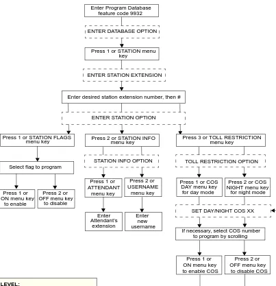
FIGURE 1.
Station Database Programming Flowchart
Enter Program Database feature code 9932
Press 1 or STATION menu key
ENTER DATABASE OPTION
ENTER STATION EXTENSION
Enter desired station extension number, then #
ENTER STATION OPTION
Press 2 or STATION INFO menu key
STATION INFO OPTION
Press 3 or TOLL RESTRICTION menu key
TOLL RESTRICTION OPTION Press 1 or STATION FLAGS
menu key
Select flag to program
Press 1 or ATTENDANT
menu key
Press 2 or USERNAME
menu key
Enter new username extension
Enter Attendant’s Press 1 or
ON menu key to enable
Press 2 or OFF menu key
to disable
Press 1 or COS DAY menu key for day mode
Press 2 or COS NIGHT menu key
for night mode
SET DAY/NIGHT COS XX
If necessary, select COS number
Press 1 or ON menu key to enable COS
If desired, select another COS number to program by scrolling
Press 2 or OFF menu key
to disable COS
to program by scrolling
YOUR INPUT
KEYSET DISPLAYS AT ANY LEVEL:
P r e s s * o r S P K R t o c a n c e l a n y u s a v e d changes and back up to exit programming. Press # or ACCEPT to save changes and back up one display level.
Page 14 Station Database Programming Flowchart
System Programming Using An Administrator’s Station
The system-wide information that can be programmed by an Administrator station includes the following:
• Define do-not-disturb messages: The system has default do-not-disturb messages in
both English and Japanese that can be reprogrammed through an Administrator’s sta-tion. (See page 189 for information concerning their use.) Administrators can delete or change messages 01-20 to any value (up to 16 characters). The current language of the programming keyset determines which list is programmed. (See page 241 for a descrip-tion of the Change Language feature.) The Japanese transladescrip-tion has the same meaning as the English message. The default messages are:
When do-not-disturb messages are changed, the programmer should attempt to keep the meanings for the messages in both lists the same. That is, if the English message 02 is changed to “PAGE ME,” a similar message should be programmed for the Japanese message 02.
• Select an Administrator database programming password: Entry to the database
programming feature at the Administrator stations can be protected using a password. A password would prevent unauthorized users from altering the system database.
• Define reminder messages: The system reminder messages can be changed using an
Administrator’s station. (See page 198 for information about using reminder messages.) The messages are limited to 16 characters each. The system has default reminder mes-sages in both English and Japanese. The current language of the programming keyset determines which list is programmed. (See page 241 for a description of the Change Language feature.) Each Japanese translation has the same meaning as the English mes-sage. The default messages are:
01 DO-NOT-DISTURB 11 OUT OF TOWN 'TIL
02 LEAVE A MESSAGE 12 OUT OF OFFICE
03 IN MEETING UNTIL 13 OUT UNTIL
04 IN MEETING 14 WITH A CLIENT
05 ON VACATION 'TIL 15 WITH A GUEST
06 ON VACATION 16 UNAVAILABLE
07 CALL ME AT 17 IN CONFERENCE
08 AT THE DOCTOR 18 AWAY FROM DESK
09 ON A TRIP 19 GONE HOME
10 ON BREAK 20 OUT TO LUNCH
01 MEETING 11 CALL ENGINEERING
02 STAFF MEETING 12 CALL MARKETING
03 SALES MEETING 13 CALL ACCOUNTING
04 CANCEL MEETING 14 CANCEL DND
05 APPOINTMENT 15 CANCEL CALL FWD
06 PLACE CALL 16 TAKE MEDICATION
07 CALL CLIENT 17 MAKE RESERVATION
08 CALL CUSTOMER 18 REVIEW SCHEDULE
09 CALL HOME 19 LUNCH
Page 15
Station Database Programming Flowchart
When reminder messages are changed, the programmer should attempt to keep the meanings for the messages in both lists the same. That is, if the English message 02 is changed to “GO TO AIRPORT,” a similar message should be programmed for the Japa-nese message 02.
• Program new extension numbers for stations: The extension number for any station
can be changed by an Administrator. The new extension number cannot conflict with an existing number.
The System-Wide Database Programming process is summarized in the flowchart shown on
page 18. See page 47 for a Program Planning Sheet.
If necessary, you can press or SPKR, to cancel programming and discard any unsaved changes, at any time during the following procedure.
SYSTEMDATABASEPROGRAMMING:
NOTE If you wish to change the Japanese do-not-disturb or reminder message sets, make sure your station is set in Japanese mode. See page 241 for an explanation of the Change Language feature.
(1) While on hook, enter the Program Database feature code (9932).
(2) If a password is required, the display shows ENTER PASSWORD. Use the keypad to
enter your 1-8 digit password and press . (If you enter an incorrect password, the dis-play shows INVALID PASSWORD.)
If a password is not required, skip this step.
(3) The display shows ENTER DATABASE OPTION. (Executive Keysets also show the options: STATION, SYSTEM, and TRUNK.) Press or the SYSTEM menu key.
(4) The display shows ENTER SYSTEM OPTION. Select one of the following:
a. Do-Not-Disturb Messages: This option allows you to program the do-not-disturb
messages used by the stations. To select it, press or the DND MESSAGES menu key. Then do the following:
1. The display shows SELECT DND MESSAGE #. Enter a message number or scroll to the desired message. (To scroll to the correct message press the Vol-ume key or the SCROLL plus NEXT and PREVIOUS menu keys.)
2. When the display shows the desired DND message, enter the new message as described in paragraph on page 9.
3. Press or ACCEPT to save the new message. The display shows DATA-BASE UPDATED and then returns to the SELECT DND MESSAGE prompt. (Or to cancel your entry, press or CANCEL. The display shows NO UPDATE PERFORMED.)
4. To program another message, scroll to the desired message and repeat these steps.
5. Press again to exit to the ENTER SYSTEM OPTION prompt.
*
#
2
1
#
*
Page 16 Station Database Programming Flowchart
b. Password: This option allows you to set a password that limits access to the
Administrator programming feature. To select it, press or the PASSWORD menu key. Then do the following:
1. The display shows CHANGE PASSWORD TO. Enter a password of up to eight digits then press . (Or, to erase the password and leave it blank, just press #.)
2. The display shows VERIFY PASSWORD. Enter the password exactly as you did in the step above, followed by . The display returns to the ENTER SYSTEM OPTION prompt. (If you hear reorder tones and see an error mes-sage, the passwords did not match and you must start over at the CHANGE PASSWORD prompt.)
c. Reminder Messages: This option allows you to program the reminder messages
used by the stations. To select it, press or the REMINDER MSGS menu key. Then do the following:
1. The display shows SELECT REMINDER MSG #. Enter a message number or scroll to the desired message. (To scroll to the correct message press the Vol-ume key or the SCROLL plus NEXT and PREVIOUS menu keys.)
2. When the display shows the desired message, enter the new message as described in paragraph on page 9.
3. Press or ACCEPT to save the new message. The display shows DATA-BASE UPDATED and then returns to the SELECT REMINDER MSG prompt. (Or to cancel your entry, press or CANCEL. The display shows NO UPDATE PERFORMED.)
4. To program another message, scroll to the desired message and repeat these steps.
5. Press again to exit to the ENTER SYSTEM OPTION prompt.
d. Station Extensions: This option allows you to assign new extension numbers to
stations. To select it, press or the STN EXTENSION menu key. Then do the following:
1. The display shows ENTER STATION EXTENSION. Enter the extension number of the station to be programmed using one of the following methods. (If you enter an invalid extension number, you hear reorder tones and must try again.)
Enter a complete number: Enter the extension number using your keypad.
When a valid number is entered, the circuit information is displayed. Press again to continue.
Enter a partial number: Enter a partial extension number then press the
key, high end of the Volume key, or the ACCEPT menu key. The display shows the extension number, user name and circuit number of the station that most closely matches the partial extension number. Press or ACCEPT to program the displayed station, or scroll to another station as described below.
Scroll through the numbers: To scroll through the extension number list,
press the high end of the Volume key or NEXT menu key to scroll forward, or press the low end of the Volume key or PREVIOUS menu key to scroll back-ward. When the desired extension number is displayed, press or ACCEPT to continue.
2
#
#
3
#
*
#
4
#
#
#
Page 17
Station Database Programming Flowchart
2. The display shows CHANGE X (number) TO EXTENSION. Enter the new extension number for the station. If you enter an invalid number, you hear reorder tones and must try again. If you entered an extension number that is
already assigned, the display shows CONFLICTING EXTENSION and hear
reorder tones. When the display returns to ENTER STATION EXTENSION, you must start over and select a new extension number.
3. Press or ACCEPT to exit to the ENTER STATION EXTENSION prompt. The display shows UPDATING DATABASE for four seconds and then DATABASE UPDATED. (Or to cancel your entry, press or CANCEL. The display shows NO UPDATE PERFORMED.) NOTE: Although the system begins to update the database when you press or ACCEPT, it may take longer than the four-second display to change the extension in the system – especially in a large or busy system.
4. Press or ACCEPT again to exit to the ENTER SYSTEM OPTION prompt. (If an extension number is displayed, press to exit, instead of or ACCEPT.)
(5) When the display shows ENTER SYSTEM OPTION, press again to exit to the ENTER DATABASE OPTION prompt.
(6) When finished with all programming, press while the ENTER DATABASE OPTION prompt is displayed. This ends the programming session.
(7) If a system reset is required, the display shows ENTER SYS RESET OPTION. Do one
of the following:
— Delayed Reset: Press or the DELAYED menu key to delay the reset. The dis-play shows DELAYED RESET SCHEDULED. The system will be reset at the pre-programmed time.
— Immediate Reset: Press or the IMMEDIATE menu key to reset the system now.
NOTE A system reset will drop all calls in progress.
#
*
#
#
* #
#
#
1
Page 18 System Database Programming Flowchart
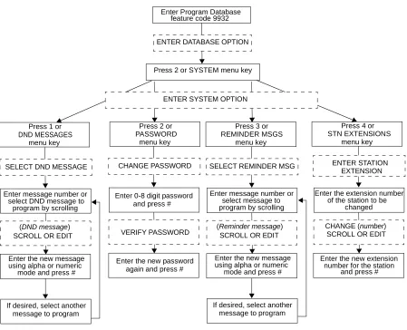
FIGURE 2.
System Database Programming Flowchart
Enter Program Database feature code 9932
Press 2 or SYSTEM menu key ENTER DATABASE OPTION
Press 2 or PASSWORD
menu key
Enter the new message using alpha or numeric
mode and press #
ENTER SYSTEM OPTION
Enter message number or select DND message to
program by scrolling Press 1 or
DND MESSAGES
menu key
Press 4 or STN EXTENSIONS
menu key Press 3 or
REMINDER MSGS menu key
SELECT DND MESSAGE
If desired, select another message to program
(DND message) SCROLL OR EDIT
Enter the new password CHANGE PASSWORD
VERIFY PASSWORD
Enter the new message using alpha or numeric
mode and press # Enter message number or
select message to program by scrolling SELECT REMINDER MSG
If desired, select another message to program (Reminder message)
SCROLL OR EDIT
Enter the new extension number for the station
and press # Enter the extension number
ENTER STATION
CHANGE (number) SCROLL OR EDIT Enter 0-8 digit password
and press #
again and press #
EXTENSION
of the station to be changed
YOUR INPUT
KEYSET DISPLAYS AT ANY LEVEL:
P r e s s * o r S P K R t o c a n c e l a n y u s a v e d changes and back up to exit programming. Press # or ACCEPT to save changes and back up one display level.