208 |
P a g e
WEB SERVER BASED AUTOMATION AND
SURVEILLANCE CONTROL
Vineeth Antony
1, Hiren Vaghasiya
2, Pooja Naik
3, Vanita Patil
41,2,3,4
Department of E&TC, Sinhgad Academy of Engineering,
SavitribaiPhule Pune University, (India)
ABSTRACT
Automation is the process of having a machine or machines to accomplish tasks hitherto performed wholly or partly
by humans. Intelligent domestic system not only can centralize and monitor affairs by gathering computer
technology, embedded technology, sensor technology, and network communication technology, but also can meet
the pursuit of high quality life in the information age by collecting the security control, lighting control, network
connection and other functions. In response to the demand, the resolution of embedded intelligence home control
system based on ARM7 has been proposed. In this project, we completely visualized operations using a core control
host computer also called as a web server and a wireless viewing system for the monitoring and controlling of the
concerned automated place. The wireless viewing system can contain both an Android Phone/tablet as well as a
desktop/laptop.
Keywords
:
Automation, Gui, Security, Surveillance, Web ServerI INTRODUCTION
Previously to the herald of automation concept control of appliances was completely manual. That is, the control of appliances was done manually by humans. With the invention of automation this aspect of work has been gradually reduced. The work of technology is to make use of newer ideas and implement it into something which will reduce the work of mankind. Gradually, several concepts were added to the idea of automation by innumerous people around the world. New ideas gave rise to new uses to automation. Our Project strives to achieve that very fundamental aspect of automation and developing another possible use of automation, which has become a must in today’s world, that is surveillance and security. This project amalgamates both these technologies into single low cost package which is more feasible for the common man.
II. BACKGROUND
209 |
P a g e
emergency system to be activated. Home automation not only refers to reduce human efforts but also energy efficiency and time saving .In response to the demand, the resolution of embedded intelligence homecontrol system based on ARM7 has been proposed. In this project, we completely visualized operations using a core control host computer and a wireless receiver and transmitter and the software and hardware platform of embedded Linux system, GUI interface and video surveillance technology.The main objective of this project is to propose a newer solution to home automation and security. Automation can be defined as the replacement of manual operations by computerized methods. Note that the concept of home automation is not new. The early prototypes of commercial products were first being developed at the end of the 1970’s, over 38 years ago. Number of attempts has been made to develop, implement and maintain standardization for control system of home automation. But the idea of extending the ways in which current systems are implemented and utilizing latest technologies to provide better results generated interest towards this project. Nevertheless the future of intelligent homes is still open.
III.
PROBLEM
Most of the available systems are not affordable for an average income earner. Therefore this solution is very cost effective with respect to most of the available systems. However our proposed system can be configured to support different levels of security. Therefore the user has the flexibility to select a security package which suits the user requirements the most. Even the installation cost of the system is low. The following are few of the problems in the previous systems which motivated us develop a new solution.
1) None of the existing systems provide the facility to expandthenumberofequipment’scontrolled/monitored unlimitedly.
2) Most of the existing systems cannot be integrated with an already built home without re-wiring. This is one of the major issues with regards to usability and flexibility of many systems. But this problem is addressed by or system by providing a flexible solution which lets the user add/remove any item to/from the system with ease.
3) Since most of the existing systems use only SMS to communicate between the serverand the mobile device the cost of these systems can be high.
4) Security level requirements are different for different users. Therefore we provide a solution which can alter the level of security.
5) Most of the existing systems are not affordable for most of the users. And some of the systems provide solutions whicharenot of much use fordomestic applications.
210 |
P a g e
IV.METHODOLOGY
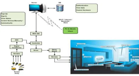
Fig1 General Block Diagram
The system can be divided into 3 sub-systems. They are A) Central Web-Server
B) Automation Sub-system C) Surveillance Sub-system D) Viewing Module
A) Central Server
The central server system includes the PC/Laptop that is used to access the internet. The primary function of this system is to continuously poll the controller to check the status of the connected appliances and keep updating the database. Also, on being alerted of an intrusion by the IR Sensors connected to the controller, an
SMS/E-mail/Android App notification is sent to the Viewing Module. This database is configured using the concept of Java Servlets. The commands to control the controller is passed on to it by the server. In addition to this, the surveillance camera is also interfaced to the server. When demanded, the server simply buffers the captured footage by the camera.
B) Automation Sub-system
211 |
P a g e
C) Surveillance Sub-systemThis system includes any device that is used to provide surveillance to any given area. This can include a laptop’s webcam, an external webcam or a wireless camera.
D) Viewing Module
Modules which are used to control the Automation Sub-system and Surveillance Sub-system are included in the viewing module. The Viewing Module makes use of the Internet to access the Central Web-Server. Using the Viewing Module changes can be made depending on the user.
Fig 2.Functional Block Diagram
V.
IMPLEMENTATION
A) Central Web-Server
212 |
P a g e
Web-Server serially. In case of break-in detected by the IR Sensor, this system notifies the user of the same using an Android App/e-mail/SMS.
B) Automation Sub-system
The Automation Sub-system is configured by interfacing the IR Sensors and the relay to the controller. The IR Sensors are used as an alerting mechanism. In case of a break-in detected by an IR Sensor, the response is updated serially to the Central Web-Server which further brings it to the notice of the user. This is done by performing signal conditioning of the IR Sensor output followed by the ADC conversion by LPC2148.
C) Surveillance Sub-system
This is implemented using the laptop’s webcam or can also include an external webcam support.
D) Viewing Module
The Viewing Module can include the Android App and laptop. Here we develop our own Android App for our purpose. The Android will first authenticate the user before allowing access to the database
VI.
RESULTS
The results below show the various screenshots of our GUI, that we have designed along with the outputs of all the attached sensors .Similarly shown is our control panel where we can control the appliances, measure value from the sensors and view the live feed.
Fig 3.Login Screen
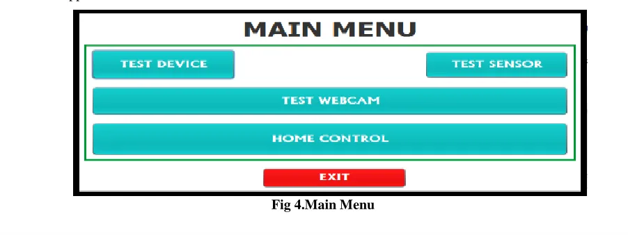
The Login Screen asks for the username and password which authenticates the user. On pressing PROCEED, the main menu appears.
213 |
P a g e
The Main Menu consists of 4 buttons which are Test Device, Test Sensor, Test Webcam and Home Control. The Test buttons are used to test the respective components. The Home Control Menu is the central part of all controls. As seen below, the various sensor channels and their thresholds can be viewed as well as set. Also, we can set the appliances, depending on our needs, by viewing the present status of the connected appliances. In addition to this, we have created a window , using which we can view the live feed.
Fig 5.Home Control Screen
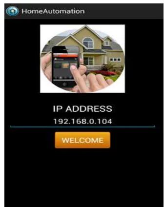
In the developed Android App, we have to first enter the server’s IP Address along with a password to get access to the database.
214 |
P a g e
On being authenticated, we enter the display window of the Android app. This window consists of the values and status of the various sensors. This window also displays the status of the device connected across the device array. Additionally, there is a window, where we can view the live feed from the webcam/camera connected to the Central Web-server
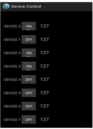
On pressing the Control Device on the right corner of the app, we go to the Control Panel. This control panel gives us the ability to control the devices connected across the device array.
Fig 7.Display Panel in Android Phone
215 |
P a g e
VII.FUTURE WORKS
Though we try to address most of the issues associated with current home automation systems, still there is room for further improvements. The project can be enhanced by sending security alerts to the regional police station when it detects a security breach. This will completely relieve the user from security threats. Currently this entire system works only with its components and does not make use of existing home automation systems. Thus project can further be improved in such a way that it will be possible to integrate with existing home automation and security systems.
Also the project can be improved to monitor the home power consumption and take necessary actions to reduce it or warn the user if it exceeds a certain limit. Furthermore, newer technologies can be implemented which can provide backup for power or internet connection problems for better safeguarding.
VIII.CONCLUSION
In this research we tried to identify the possible areas in home automation and security that can be improved and proposed a new system which addresses them. A new home automation and security system was developed along with this research and tested in the real environment. The unique model designed to implement this system and different methods were discussed in detail. But since the area of home automation is very vast, more room is still available for further enhancements.
REFERENCE
[1] Ping LJl, jian-PING LJl, Embedded Intelligent Home Control system based on ARM-Linux, School of Computer Science and Engineering, University of Electronic Science and Technology of China, Chengdu
[2] K. Atukorala, Smarteye- Integrated Solution to Home Automation, Security and monitoring through mobile phone, University of Oulu , Oulu, Finland