Real-Time Simulation of Force Parameters for Diagnostics of
Ceramic Tool Condition During Milling of High-Hardness Steel
Parts
Marina A. Volosova1,*, Vladimir D. Gurin1, Anton E. Seleznev1, Leonid E. Shvartsburg1 and Mariuch Jenek2.
1
Moscow State Technological University "STANKIN", Department of High-Performance Processing, RU-127055, Moscow, Russia
2
Institute of Machine Construction and Operations Engineering,University of Zielona Gora, PL-65-246, Zielona Gora, Poland
Abstract. Cutting ceramics is a high-performance tool material for high-speed machining of hard steels and alloys. Ceramic materials have high hardness and heat resistance in a wide range of temperatures, as well as chemical passivity in relation to most of the workpieces. However, the wider application of ceramic cutting tools is limited due to the low reliability - unpredictable fragile fracture of the cutting edge in different periods of operation. The study discusses mathematical simulations of force parameters in the milling of hardened steels using ceramic cutting tools. The simulation results were used to develop a system for the metalworking technological system state diagnostics. Mathematical software for calculations of the set of force parameters through computer simulations with taking into account the tool wear has been developed. The developed system allows calculating and graphically displaying a set of force parameters appearing during face milling of hardened steels in the real-time.
1 Introduction
In modern industrial production, the problem of reliable functioning of advanced technological equipment during its continuous operation is of great importance. The downtime related to the failure of the working condition of the technological system should be minimized. It is possible only if the reliability at of all the components (elements) of the system is pretty high, and at the characteristic time in whichf the working condition of the technological system can be restored after failure is pretty low . The observations show that in the case of untimely detection of cutting tool failure, the reliability of the metalworking technological system can be greatly reduced.
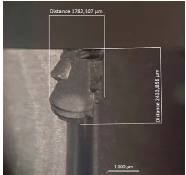
The ceramic is a high-performance tool material for high-speed machining of hard steels and alloys. It has high hardness and heat resistance in a wide range of temperatures, as well as chemical passivity in relation to most of the workpieces. However, the wider application of ceramic tools is limited because of its low reliability - unpredictable fragile fracture of the cutting edge in different periods of operation. This is especially typical for machining processes where non-stationary (variable) operating conditions of ceramic tools are observed, for example, in the milling process, when the parameters of the milled workpiece layer change in one working stroke of the tool tooth. Today, the improvement of the quality of ceramic tools is directed to the exclusion (minimization) of failures in the form of brittle failure (Fig. 1). Brittle failure is often a sudden event and is one of the unpredictable failures of a tool that reduces the
reliability of the technological system when manufacturing parts on CNC machines [1,2,3].
Fig. 1. Brittle fracture (cracking) of the ceramic cutting tool during the milling process.
problems: during roughing and semi-roughing, functional failures related to tool failures due to brittle failure and/or catastrophic wear and tear are detected. In part finishing, parametric diagnosis is provided, and problems in the part quality are detected. It is highly preferable to prevent or to fix problems during the machining process rather than after the part has been manufactured, when it can be very expensive to remove the defect.
The further improvement of the effectiveness of hardened steel machining in automated production is the application of real-time diagnostics of ceramic tools. The diagnostics of the tool conditions allows exploiting of the cutting tool up to its maximum service life and provides a high probability of its trouble-free operation. In the absence of a diagnostic system, this is very difficult [6,7]. The practical possibility of using the tool diagnostics system in real-time depends on the availability of models, techniques, and algorithms. They allow calculating and revealing diagnostic signs of the tool condition based on functional dependencies between the parameters of the cutting process and tool wear at certain cutting conditions. The diagnostics of such complicate processare typically based on mathematical modeling.
2 Mathematical modeling of force
parameters in milling operations
2.1 Measuring instruments, tools and materials
The study of force parameters was carried out using the measuring complex of Kistler company, which includes a high-precision multicomponent dynamometer Multicomponent Force Plate. The system was mounted on the work platform of the FSS450MR vertical milling machine. A rectangular billet made of 102Cr6 (HRC 62÷63) material was used as a workpiece for the experiments. The tool used was a 100 mm diameter face milling, which was equipped with square ceramic inserts. Ceramic inserts were made of aluminum oxide with titanium carbide addition (model CC650 by Sandvik Coromant).
The geometric parameters of the ceramic insert mounted in the milling machine were as follows
° − = 26
γ , α =6°, ϕ=84°, λ=+5°, ϕ1=6°, .
8 , 0 мм
r= :
2.2 The coordinates of the simulated force parameters for face milling
Our previous studies have shown [8,9] that the wear on the main back surface (hb) is the failure criterion for the face milling of hardened steels with ceramic inserts. Moreover, in refs. [10,11,12], the priority of force parameters for the diagnostics of the milling cutters has been proved. Force parameters are the most informative) indicators that reflect the wear of ceramic inserts during face milling of hardened steel.
In order to calculate the cutting forcecomponents at each moment of milling of hardened steel with tools equipped with ceramic inserts (including coated inserts), the original mathematical modelwas developed. With its help, the analysis and selection of the force diagnostic features of the tool conditions have been provided, including the cases when n plates (n>1) simultaneously are involved in the process.
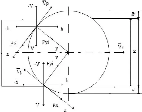
The scheme of the relative position of the tool bit axis (the milling cutter) and the workpiece shown in Fig. 2 allows simulating the force parameters both at symmetrical face milling and at the shift of the milling cutter relative to the center of the workpiece. This is
achieved by changing the parameters
x
l andx
p at the shown directions of action of the cutting motion vectorp
V and the feed motion vector Vs .
The force parameters Pz- tangential force, Py- radial force, Px- axial force are considered to be valid for the cutting inserts in the plain Cartesian coordinate system (x,y). Force
i V
P is orthogonal to force Ph,
which in turn is parallel to the feed vector Vs. They are considered in quasi-fixed plain Cartesian coordinate systems (−h,−V ); (−V,h); (h,V); (V,−h) depending on their sign and direction of action, determined by the simulation.
Fig. 2. Scheme of mutual position of the tool and the workpiece, as well as the coordinates of the simulated force parameters during face milling.
2.3 The sequence of actions in the process of simulation of force parameters
The simulation algorithm includes the following activities in sequence:
1. Initial parameters of the simulation: V [m/min] – milling speed;
B [mm] – milling width; t [mm] – milling depth;
min
S [mm/min] – minutes feed rate;
z
– number of cutting inserts (teeth) of the milling cutter;b
h [mm] – wear on the main back surface;
l
x ,xp [
mm
] – variable parameters;r[mm] – radius at the top of the cutting insert; 1
K – correction coefficient for the hardness of processed material;
2
K – correction coefficient for coating;
3
K – correction coefficient considering tool geometry.
2. Verification of initial parameters and their correction:
p K D B x
x = − − , if xK ≠xp, then it is necessary to correct the initial parameters;
r
t≤ – milling depth limitation.
3. Determining the radius of the milling cutter:
2 D
R= (1)
4. Calculation of the cutter's tooth rotation:
R x R R
x
R l p
В=180−arccos − −arccos −
ψ (2)
5. Tooth pitch calculation of the milling cutter
ψ
z:z
z =360
ψ (3)
6. Calculation of the maximum number of
simultaneously operating teeth
z
j:z В j z ψ ψ
= (4)
In case of j≤1, then zj =1, if j>1, then
1 + =x
zj , where
x
– integer part of numberj
.7. Determining the angle of rotation
ψ
0 of thecutting insert in the presence of an offset
x
l:R x R− l
=arccos 0
ψ (5)
8. Calculation of the feed per tooth
S
z:z n S Sz
⋅
= min (6)
D V n ⋅ ⋅ = π
1000 (7)
9. Calculation of instantaneous force parameter values Pzi, Pyi, Pxi:
a) set the valueψi =i⋅∆, where
K
n ... , ,
i=012 ψ ,
whereψK =180°:
∆ ψ
ψK K
n = (8)
b) calculation Pzi, Pyi, Pxi:
provided that 0<ψ ≤i ψ0: Pzi =0, Pyi =0, Pxi =0;
provided that 0<ψ ≤i ψB:
+ =2600,8( sin )0,75
i z zi t S
P ψ 11 , 0 75 . 0 8 .
0 ( sin ) 101t Sz ψi hb
+ (9)
+ =1300,98( sin )0,5
i z yi t S
P ψ 22 , 0 5 . 0 98 .
0 ( sin )
162t Sz ψi hb
+ (10)
Pxi =210t0,75(Szsinψi)0,75+ +693t0,75(Szsinψi)0,7hb0,38 (11)
After elementary transformations mathematical models (7), (8), (9) are more convenient for calculation of force parameters:
× =260 0,8( sin )0,75
i z zi t S
P ψ
z z
z P P
P
з K K K
h0,11) 1 2 3 39
, 0 1 ( +
× (12)
× = 0,98 0,5
) sin (
130 z i
yi t S
P ψ
y y
y P P
P
з K K K
h0,22) 1 2 3 24
, 1 1 ( +
× (13)
× =200 0,75( sin )0,6
i z xi t S
P ψ
x x
x P P
P з K K K h0,4) 1 2 3 03
, 3 1 ( +
× (14)
Provided that 0<ψi ≤180°: Pzi=0, Pyi=0, 0
=
xi
P .
10. Calculation of instantaneous force parameter values PVi,Phi:
i yi i zi
hi P cos P sin
P = ψ + ψ (15)
i yi i zi
Vi P sin P cos
P = ψ − ψ (16)
In case of 90°≤ψi ≤180°, the function conversion formulas are used
sin
ψ
i,cos
ψ
i, where' i
i ψ
ψ =90°+
11. In case of
z
j=
1
, the sensitivity coefficients foreach force are calculated from their maximum values
max
K
, as well as the average values−
K
: % P P P K ] h max[ ] h max[ ] h max[ max b b b 100 0 0 ⋅ − = = = (17) % P P P K ] h [ ] h [ ] h [ b b b 100 0 0 ⋅ − = = − = − − − (18)a) in case of
z
j>
1
, then the total forces are furthercalculated
P
ziΣ ,P
yiΣ ,P
xiΣb) it is necessary to calculate the discrete values of
the milling cutter's angle of rotation ψi' within the milling cutter's pitch ψz, which is the period of repetition of the total force parameters in the milling
conditions in consideration ψi' =i∆, where
B
n
∆
ψ
ψB B
n
=
(19)c) must be defined the discrete values of rotation
angle
ψ
iz'of each insertz
in the areaψ
B,whereK=1,2,...nz,nz =zj;
provided that
ψ
iz1'=
0
, ∆ψ0 0≤i≤ ;
provided that
ψ
iz1'=
i
∆
,∆ ψ ∆ ψ z i≤ < 0 ;
provided that ψizK' = (k−1)ψz +i∆,
∆ ψz i≤ ≤
0 ;
where
2
≤
k
≤
z
j;provided that ψiznz' = (nz −1)ψz +i∆,
∆ ψ
ψ 0
0≤i≤ z − ;
provided that '
=
0
z izn
ψ
, ∆ ψ ∆ ψψz z
i≤ < − 0
.
12. Calculation of total instantaneous force
P
ziΣ:∑
==
n k ziK ziP
P
1Σ (20)
13. Calculation of total instantaneous force
P
yiΣ:2 ' 2 '
)
(
)
(
Σ ΣΣ
=
±
Vi+
hiyi
P
P
P
(21)∑
= Σ=
±
n k izk yiK ViP
P
1 ' 'cos
ψ
(22)' 1 '
sin
izK n k yiK ziP
P
∑
ψ
=
Σ
=
(23)14. Calculation of total instantaneous force
P
xiΣ :∑
==
n k xiK xiP
P
1Σ (24)
15. Calculation of total instantaneous forces
P
ViΣ ,Σ hi
P
: Σ Σ Σ ΣΣ zi ψi yi ψi
hi P P
P = cos + sin (25) (26)
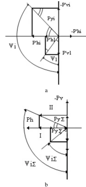
The angular coordinate ψiΣ (Fig. 3) of the application point on a circle with a radius
R
. and the resulting total cutting force is as follows:In case of
P
ViΣ'≥
0
, thenΣ Σ Σ ψ yi ' hi i P P arcsin
= (27)
In case of PViΣ' <0, then
Σ Σ Σ ψ yi ' hi i P P arccos +
=90 (28)
16. Calculation of the sensitivity coefficient of the resulting total forces:
%
P
P
P
K
] h max[ ] h max[ ] h [ max P max b b b100
0 0⋅
−
=
= = ΣΣ (29)
%
P
P
P
K
] h [ ] h [ ] h [ b b b100
0 0⋅
−
=
− = − = − − Σ Σ ΣΣ (30)
The constants and degrees of influence of the arguments included in models (12), (13), (14) were obtained experimentally through an original method [5].
a
b
Fig. 3. Force vectors acting on the face milling cutter inserts: a) to calculate the total forces; b) to calculate the angular coordinate.
2.4 Software package for simulation of force parameters
In order to select the force diagnostic features of the tool state and to assign its limiting value, a computer program for modeling the cutting force components of milling hardened steels with face milling cutters with ceramic inserts has been developed. The program was based on the algorithm described above. The program was written in Microsoft Visual Studio 2015 environment. C++ language was used in programming.
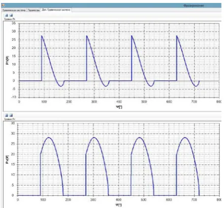
accuracy of simulations of force parameters with the developed mathematical model and software.
It has been found that the most noticeable increase is observed in the case of axial force (more than 250%). The increase in other forces is also quite big and can be used for the diagnostics of conditions of face milling cutters with ceramic in hardened steel processing.
Fig. 4. The interface of the force parameter simulation program.
3 Practical implementation of
simulations of force parameters on a
CNC machine tool in milling operations
A universal solution based on the use of an external computer for simulations of the force parameters is the most efficient way of r the diagnostics of g conditions of ceramic tools. The versatility of the solution arises from the possibility of its application to existing CNC systems of various manufacturers without changing their architecture [11,12,13]. Monitoring and diagnostics operations are performed with the external computer based on an industrial PC. Control signals that are transmitted to the CNC system via the controller of electric automatics. The system is based on measuring the cutting force components, one of which is used to determine the condition of the tool.
The developed system has been tested on the Siemens Sinumerik CNC milling machine [14]. The external computer is connected with the inputs and outputs of the CNC controller S7-300 via a device that converts the input signal from the external computer of the TTL-level into the 24V level signal. The controlling program of the automation system is adapted to the existing task. The new version of the controlling program is integrated into the PLC system of the CNC with the use of a special hardware-software suite - communication card Simatic S7 Step7v.5.4SP3.1. The use of system variables in the CNC system Sinumerik has been implemented interaction of the diagnostics
module with the core of the CNC system and the function of adaptive control.
The diagnostic system,, allows significantly reducing the percentage of defects obtained in the case of failure of the tool before the end of the processing ), and increasing the productivity of cutting up to 25%, while reducing the consumption of the tool up to 90%.
4 Conclusions
The developed software allows calculating and graphically displaying a set of force parameters arising at face milling of hardened (bearing) steels in a wide range of processing factors with taking into account wear of cutting ceramic inserts. This allows analyzing the whole set of the cutting force component to select the power diagnostic feature of the tool condition and calculate its limit value.
It has been found that the maximum values of cutting forces in the case of milling with the sharpened tool, getting positive or negative values, can decrease or increase when milling tool teeth are worn out, depending on the schemes used and factors of machining. The priority indicator of milling power parameters' estimation at tool diagnostics is the coefficient of informativeness determined by the average values of instantaneous forces in the period of a particular rotation angle or the period of milling cutter operation time, assigned depending on the number of simultaneously working tool teeth.
On the basis of the theoretical research and experimental studies it is shown that application of diagnostics of the tool in real-time depending on dispersion of the operating time up to failure and probability of trouble-free operation of the tool. It allows to increase the productivity of cutting by 30 % and to lower expenses for the tool operation by 90 %.
The technique of finding instantaneous values of cutting force components during milling is developed and experimentally confirmed, which allows studying power parameters with sufficient accuracy and reliability taking into account the milling cutter failure criterion.
The result of the work is the development of mathematical model and computational code for the selection and calculation of the maximum allowable values of the force diagnostic feature of the milling cutters in the process of cylindrical and face milling at the counter and associated schemes of processing of surfaces, ledges, and grooves.
Acknowledgements. We would like to thank the Ministry of Science and Higher Education of the Russian Federation for supporting this work under grant № 074-11-2018-011 implement in the framework of the Decree of the RF Government No 218 dd. 09.04.2010. This work was carried out using equipment provided by the Center of Collective Use of MSUT "STANKIN".
1. S. Grigoriev, A. Metel, Nanostructured thin films and nanodispersion strengthened coatings 155, 147-154 (2004)
2. S.N. Grigoriev, Yu.A. Melnik, A.S. Metel, Surface and coatings technology 156(1-3), 44-49 (2002) 3. M.A. Volosova, V.V. Kuzin, Metal Science and Heat
Treatment, 54(1-2), 41-46 (2012)
4. S.N. Grigor’ev, V.V. Kuzin., Glass Ceram, 68(7-8), 253-257 (2011)
5. S.N. Grigor’ev, M.A. Volosova, Meas. Techn., 59(9), 951–954 (2016)
6. M.A. Volosova, V.D. Gurin, J. Frict. Wear, 34(3), 183-189 (2013)
7. S.N. Grigoriev, V.D. Gurin, M.A. Volosova, N.Y. Cherkasova. Materialwiss. Werkstofftech, 44(9), 790–796 (2013)
8. U.S. Patnaik Durgumahanti, Vijayender Singh, P. Venkateswara Rao, Int. J. Mach. Tool Manu., 50(3), 231–240 (2010)
9. M.P. Kozochkin, A.N. Porvatov, F.S. Sabirov, Meas. Techn., 56(12), 1414-1420 (2014)
10. S.N. Grigoriev, M.P. Kozochkin, F.S. Sabirov, and A.A. Kutin, Proc. CIRP, 1, 599-604 (2012)
11. S.N. Grigoriev, V.A. Sinopalnikov, M.V. Tereshin, and V.D. Gurin, Measur. Techn., 55(5), 555-558 (2012)
12. S.N. Grigoriev, V.D. Gurin, M.A. Volosova, and N.Y. Cherkasova, Materialwiss. Werkstofftech., 44(9), 790-796 (2013)
13. S.N. Grigoriev, G.M. Martinov, Proc. CIRP, 41, 858-863 (2016)