Thesis
by
Linus Pauling
In partial fulfillment of the requirem&.u.r..s
for the degree of Doctor of Philosophy in Chemistry
California
Institute of Technology
Pasadena,, California
Bv RoscoE G. DICKINSON1 AND Lrnus PAULING Received April 24, 1923
The mineral molybdenite, MoS2, is described 2 as occurring in hexagonal
crystals with a very complete basal cleavage. A study of its crystal struc-ture has been carried out using X-ray spectral photographs and Laue photographs treated as previously described. 3 Since the crystals bend very easily and inelastically, some r1iffic111ty w~.s PxpniPnred in obtaining good
Laue photographs. However, the following procedure resulted in very satisfactory photographs: a crystal considerably thicker than the desired
section was selected and one fmrfoce clea.,,ed away; the cleavage face was
then cemented to a cover glass and the specimen thus supported cleaved to the desired thickness and photographed without removal from the glass.
A Laue photograph taken with the incident beam normal to the basal plane possessed a hexagonal axis and (:) symmetry planes. Several photo-graphs were made with the beam somewhat inclined to this position.
The Unit of Structure
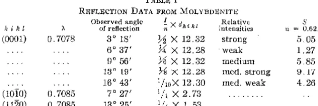
Angles of reflection of the molybdenum Ka radiation from the faces (0001), (lOlO), and (1120) are given in Table I. 'l'he n~flt><'tions from the
last two faces were obtained by transmission of the beam through the crys-tal; in these cases the a doublet was not resolved. A density determi-n::ition carried otttV1iith a pycnometer using benzene gave theva.lue 1.02 g./cc.
I~rom this the number of molecules in a unit having doao1 6.15
A.
and d1010 2. 73 is found to be 0.988. T'he axial ratio of this unit is 1.95;cor-respondingly the angle between the faces (2021) and (0001) should be 77° 28.6'. Direct observations2 have given values from 70°_ 28' to 77° 13',
the last being the usually accepted value.
"i kl
(0001)
)I Q_7078
TABLE l
REFLECTION DATA FROM .MOLYBDENln; Observed angle
of reflection
Relative intensities
3° 18' J.,~ X 12.32 strong
5° 37' 'A X 12.28 weak
9° 55'
Ytl
X 12.32 medium13° 19' 7~ X 12.28 med. strong
16° 43' :hoX 12.30 med. weak
(lOlO) 0.7085 7° 27' 1/i X 2.73 ... .
(1120) 0.7085 13° 25' 1/1
x
1.53 ... .s
u = 0.621 5.05 1.27 .5.85 9. l'/
4.25
\Vhen indices were assigned to the Laue spots on a basis of this unit, values of n A. as low as 0.13
A.
were found. As the minimum wave length1 National Research Fellow in Chemistry.
2 Hintze, "Handbuch der Mineralogie," Viet and Co., I.,eipzig, 1904
1 vol. l, p. 410.
June, 1923 CRYSTA!, STRUC'l'URE Oit MOI.,YBDENITE 1467
present was about 0.24
A.,
this unit is not possible. A unit having dooo1 =12.30
A.
and an axial ralio :3.90 and containing, therefore, 2 MoS2 gave no impossible values of n)..; this unit is the smallest one possible and all of the indices used in the remainder of this paper refer to its axes.The Arrangement of the Atoms
Reference to a tabulation 4 of the coordinates of equivalent points in
space groups isomorphous with the point-groups D3h, Cnv, D5, and D6h shows that there is a variety of ways of arranging 2 ~1oS2 in an hexagonal unit in such a way that the molybdenum atoms are in equivalent positions, and likewise the sulfur atoms. Some of these arrangements can be ob-tained by placing 1 MoS2 in the smaller unit shown to be impossible. Ex-cluding these, the following distinct arrangements remain .
1.
2.
3. 4. 5. 6.
..--Mo at-~
(BO) (HO)
(OOv) (00:;-,)
(000) (001) (OOi) (OO})
urn mn
arn mu
~---·Sat---··-~
(nu) mu) CHu) (Hu) (Hu) (Bu) (Hu) (Bu)
<Bu) CBu) O·~·~-u) O+~+u)
(Hu) (Hu) (l·H-u) (~·H+u)
(OOu) (OOu) (0,0, ~ +u) (0,0, l-u)
. (Hu) (Hu) <s+!-u) Ci+!+u)
Arrangements 1 and 2 make it difficult to account for the absence of odd orders from (0001), and the absence of all first orders from planes having
A(h.
+
2i) integral and l odd. Any of the remaining arrangementsac-counts for the above observations.
The value of S
=
..J A 2+
B2 for planes having ~(Ti+
2-i) not integraland l odd is always 2 1\ifo for Arrangement 3; therefore, at a given wave length such planes should always reflect more weakly the smaller the value of d/n.. 'l'his is not at all in accord with the Laue photographic data, hence Arrangement 3 is impossible.
From (0001) the eight order was slightly stronger than the sixth and much stronger than the fourth. Assuming that a molybdenum atom has at least twice the reflecting power of a sulfur atom (the respective atomic numbers are 42 and 16) it can readily be shown that these (0001) intensities necessitate giving u a value between 0.11 and 0.15 or between 0.61 and 0.65 in Arrangements 4, 5, and 6. On Laue photographs, planes of the fom1s
I
3145} and { 3143} were found to reflect much more strongly than {3141} in spite of their smaller spacings. The value ofS
for these planes is given by S=
2 S [cos 211'(~+
lu)+
cos 27l'(h - lu)] for either Arrangment 4 or 5. The possible values of u makeS
differ only moderately for these 3 forms and never in such a way that the first 2 are both greater than the third. Hence Arrangements 4 and 5 are impossible.1468 ROSCOE G. DICKINSON AND LINUS PAULING Vol. 45
For Arrangement 6 the values of Sare given by the following equations.
Class 1:
!
(h+
2i) integral, l even.l
n = 1; S = 2 Mo
+
4( -1)2S
cos 2irl uClass 2: l (Ti I 2i) not integral, I even.
l
n = 1; S =Mo - 2(-1)2
S [cos 2'1T(-} +tu)+ cos 2ir(!-l u)]
Class 3:i
(h+
2i) integral, l odd.n = l; S = O.
n = 2; S
= 2 Mo - 4 §cos 4ir
l u Class 4:!
(h+
2i) not integral, l odd.1+1
n = 1;
.s
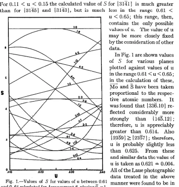
'i/3 Mo+ 2(-l)T S [cos 2'1T(t +tu) - cos 2'1T(!-tu)jFor 0.11
<
u<
0.15 the calculated value of S forl
3141 J is much greaterthan for {3145} and \:3143}, but is much less in the range 0.61
<
s
u
Fig. 1.-Values of S for values of u between 0.61 and 0. 64 calculated for Arrangement 6, placing§ 1.
The first number on each curve indicates the class of plane and the second the value of l. Thus 4 - 5 is the curve for any plane of Class 4 having l = 5.
u
<
0.65; this range, then, contains the only possible value:; uf u. 'l'he value of u may be more closely fixed by the consideration of other data.In Fig. 1 are shown values of S for various planes plotted against values of u in ihe range 0.61<u<0.65; in the calculation of these, ;Mo and Shave been taken proportional to the
respec-tive· atomic numbers. It
wasfound that
\336.10}
re-flected considerably more
strongly than { 145.12];
therefore, u is appreciably greater than 0.614. Also { 2359} ;;::; { 2357} ; therefore, u is probably slightly less
than 0.625. From these
and similar data the value of
u is taken as 0.621 ± 0.004.
All of the Laue photographic data treated in the above manner were found to be in agreement with the values
of S calculated using u
=
com-JnnP, 1923 CR.VS'l'AI. S'I'RUC'l'U~ Or' MOLYDDUNI'l'U 14G9
parisons were made between planes of different classes, requiring a more
ac-curate knowlerlgf' of Mo and §, the agreement was not so good, although
on the whole satisfactory. The extent of this agreement is illustrated by typical data given in Table II.
TAB!,!; II
LAU~ PlWTOGRAPIIIC DATA F.ROM MOLYBDitNIT~
Incident beam 8° 20' from normal to (0001). Crystal thickness 0.23 mm.
Estimated
s
hi kl Class nl\ d intensity u ~ 0.621
2021 4 0.37 1.36 3.2 2.17
1231 4 .40 1.03 1.4 2.17
3122 2 .38 1.02 0.8 2.53
3213 4 .34 1.00 6.0 7.18
23I4 2 .37 0.98 0.15 0.64
0335 3 .37 .85 0.0 0
4223 3 .36 .77 0.0 0
3412 2 .38 .75 0.3 2.53
4225 3 .39 .75 0.0 0
3143 4 .36 .74 2.6 7.1R
3145 4 .34 .72 2.0 6.68
2427 ;~ .40 .72 0.0 0
4316 2 .38 .71 0.3 2.93
1437 4 .36 .70 0.3 1 .'70
2533 4 .36 .62 1.0 7.18
5325 4 .37 .61 1.0 6.68
1543 3 .34 • 51J 0.0
o·
5237 4 .37 .59 0.15 1.70
1454 1 .37 .59 0.15 1.27
5328 2 .37 .58 0.2 4.58
4156 1 .37 .57 0.6 5.85
2359 4 .36 .57 0.2 2.71
5147 3 .3G .56 0.0 0
4158 1 .34 ss 0.8 9.17
451.10 1 .34 .54 0.3 4.26
154.12 1 .39 .52 faint 0.72
3635 3 .36 .51 0.0 0
2°54ll 4 .::>5 .50 0.3 6.68
633.10 1 .34 ,48 0.15 4.26
624.11 4 .37 .47 0.2 7.58
Discussion of the Structure
The arrangement found to account for X-ray data from molybdenite is shown in Fig. 2. This arrangement is derivable from the space group
D!h as well as from the space groups D~h• D~, qh, and Did· Considering
the atoms as points or spheres, the structure then has holohedral hexagonal symmetry.
Small, very thin crystals of molybdenite may be made by fusing together ammonium molybdate, sulfur and potassium carbonate.• We have
ex-5 Guicharn, Amt r.him. phy~ .. [7J ?.3, 552 (1901). Hintze, Ref. 2, p. 418, also
1470 KOSCO.I:<; G. DlCKIN~ON AND LINUS PAUJ,ING Vol. 45
amined crystals made by this method and have found them to be fre-quently triangular rather than hexagonal plates. Guch a face developmeul is not to be expeeted if the symmetry is that of the hexagonal holohedry. Several explanations of this apparent discrepancy are possible: (1) The
artificial crystals may have a structure di1Tereul frum Lhal uf Lite Halurnl mineral; satisfactory Laue photographs from the artifieial crystals were not obtainable to decide this point. (2) The stmcture may be the same in both
cases and the natural crystals twim1eLl su a::; lu simulate the higher sym-metry; however, we have not found it possible to account for the X-ray data on this hypothesis. (3) Although the strueture found has holohedral sym-metry fur the 11usiliuu::i uf Lhe alums, it may have a 3-fold symmetry a.xis when the shapes of the atoms or the bonds between them are considered. "" That this is a possible explanation follows immediately from .,~~~1111 the fact that the structure is derivable from the space group
-~.~A-•·MoQ-S
Fig. 2.-Ar-rangernent of the atoms in
D~h or Did·
In the structure found, each sulfur atom is equidistant from J molybdenum atoms, and each molybdenum atom is surrounded by six equidistant sulfur atoms at the corners of a small triangular prism whose altitude is ~U 7 0.10 and whose edge is ;·U5 :±: 0.02. The distance from the
molyb-denum atom to these nearest sulfur atoms is then 2.41 ±
0.06. This distance is in good agreement with Bragg's hy-pothesis of constant atomic radii. 0 Taking the radius of
molybdenum as
L:.w,
which is half the distance between the atoms in the metal (Wyckofi7 has shown this to beconsis-muly btleuitc, tent with the distances in silver molybdate, Ag2Mo04), and
MoSi. the radius of sulfur 1.05 as given by Bragg, the sum is 2.41.
On the other hand, the 2 sulfur atoms marked A and B in Fig. 2, which should also be in contact on Bragg's hypothesis, are at a distance of 3.49
A.,
while constant radii require 2.10. These relations are analogous to those found in cadmium iodide, 8 and in tin tetra-iodide. 9 This great dis-tance between sulfur atoms is undoubtedly connected with the excellent basal cleavage of molybdenite.Summary
The mineral molybdenite has been investigated by means of spectral and I,aue photographs and, with the aid of the theory of space groups, the simplest structure capable of accounting for the X-ray data has been de-rived. This structure, which is of a new type, contains 2 Mo&.i in an hexag-onal unit having d0001 12.30
A.
and an axial ratio 3.90. TheJune, rn2;3 CRYSTAL STRUCTURE OF MOI,YBDENITE 1471
denurn atoms are at (~U)
(iU)
and the sulfur atoms at CHu) (~~11) (i·H-u)[Reprinted from the Journal of the American Chemical Society, Vol. XLV. No. 12. December, HJ2:J.~
[CONTRIBUTION FROM THE GATES CHBMICAI. LABORATORY, CALIFORNIA fNSTITU1'E OF TECHNOLOGY, No. 28)
THE CRYSTAL STRUCTURE OF MAGNESIUM STANNIDE
BY LINUS PAULING
Introduction
The temperature··composition diagram 1 of the binary system,
magncsium-tin, shows a pronounced maximum corresponding to the composition Mg2Sn. This compound is described2 as cubic with octahedral habit and complete oetahedra1 deavage. For the purpose of obtaining information regarding the nature of intermetallic compounds, crystals of magnesium stannide, Mg2Sn, have been investigated by means of X-rays, resulting in a complete
determination of their structure. No crystal structure determination for an intermetallic compound has been previously reported.
By melting the calculated amounts of magnesium and tin in an iron cru-cible under a mixture of potassium and magnesium chlorides, and cooling slowly, a mass of magnesium stannide was obtained from which individual crystals could be cleaved. The X-ray data were obtained from Laue and spectral photographs, treated as described by Dickinson. 3 I wish to ex-press my thanks to Dr. Roscoe G. Dickinson for his advice and active in-terest in this research.
The Determination of the Structure
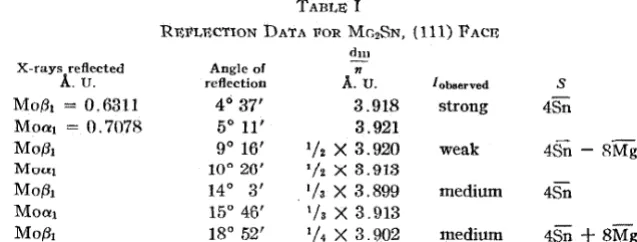
Spectral data from a (111) face of a crystal of magnesium stannide are given in Table I. Using the value of 3.591 for the density,2 these data
place
n
3/m
= 0.248 for the first reflection. No reflections were found onthe Laue photographs with values of n).. less than 0.26
A.
U., calculated forthe unit containing four Mg2Sn, with n = 1, and d1oo = 6.78 ± 0.02
A.
U. 1 Kurnakow and Stepanow, Z. anorg. Chem., 46, 177 (1905).2 Sustschinsky, Z. Krist., 38, 265 (1904).
2778 LINUS PAULING Vol. 45
As the lower limit of X-rays present in the spectrum was 0.24
A.
U ., a larger unit of structure is not indicated.A symmetrical Laue photograph through the (111) face showed a trigonal axis and three reflection planes; consequently only arrangements derived from point-groups T d' 0 and Oh were treated. No planes but those with
all indices odd gave values of
n>.
less than 0.50, although a large number of other planes were in positions favorable for reflection, so treatment was given only to arrangements based on a face-centered lattice. There are three ways4 of arranging 4Mg2Sn with these restrictions, irrespective of any
assumptions regarding the equivalence of atoms of one element. These are I Sn at 000,
HO,
!O!,OH
Mg at Hi. Ht Ht Hi, Hi. Ht Hl. Hi
II Sn at 000, HO, !O!, OH
Mg at Hi, H!. Hi, Hi, H!. !OO, O!O, OO! III Sn at 000, ~ ~O, ~Ot OB
Mg at
Hi, iH. Ht iH,
H!, 100, O!O, 00~The intensity of the third order (111) reflection is greater than that of the second order, and the structure factor, S - ..J A2 I B2 , must be greater for the third order. For Arrangements II and III, the corresponding values are
n - 2, A - D O; n 3, A tSn - 4M~, D = ± 4Mi:;·
On the very safe assumption that an atom of tin scatters X-rays more strongly than an atom of magnesium, the value of S for the third order is less than that for the second order, eliminating these two arrangements.
For Arrangement I reflecting planes may be divided into three classes, which have the following values of S.
Class I: hkl one odd, two even; n = 1, S = O; n = 2, S = 4E;"n-8Mg Class II: hkl all odd; n = l, S
=
4SnClass III: hkl two odd, one even; n
=
1, S=
O; n = 2, S = 4Sn+
SJ\!g. On the previously made assumption regarding relative reflecting powers, the values for the structure factor of the classes of planes increase in thisTABLE I
REFLECTION DATA FOR Mc2SN, (111) FACE
d111
X-rays reflected Angle of n
A. U. reflection A. u. I observed s
Mo/31
=
0.6311 4° 37' 3.918 strong 4SnMoa1 0.7078 5° 11' 3.921
Mo/11 9° 16' 1
/2
x
3.920 weak 4Sn - 8MgMou1 10~ 20' 1/2 x
3.913
Mo/31 140 3' . 1/a X 3.899 medium 4Sn
Moa1 15° 46' 1/s X 3.913
Mo/31 18° 52' 1
/4
x
3.902 medium 4Sn+
8Mg4 Wyckoff, "The Analytical Expression of the Results of the Theory of Space
Dec., 1023 CRYSTAL STRUCTURE OF MAGNESIUM STANNIDE 277\1
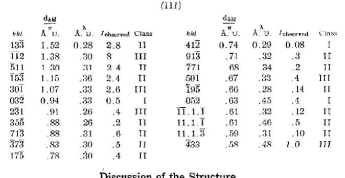
order: I, II, III. Intensity data showing the extent of the agreement with this structure are given in Tables I and II. In comparing intensities of two planes reflecting at the same wave length, if the intensity of t11e plane with the smaller value of d/n is larger than that of the other, the structure factor of the first must be greater than that of the second. No intensity relations not arcounted for by the above arrangement were observed.
TABLE II
f.-AUE PnoToGKAPnrc DJ\'fl\ I'OR MG2S.N. INCHJl~N'f BHAM fzn ao' FI<:.OM NoR.MJ\I, Tn
(111)
dkkz dkkl
hid Anu. A.
"
U. I ohscrvcd Class hkl A. n u. A.\. lohf\crvr:d Class133 1.52 0.28 2.8 IT 412 0.74 0.29 0.08 I
IT2 1.38 .:30 8 III 913 . 71 .32 .3 J[
)) 11 1 ::!fl
:n
2 4 TT 771 .R8 .34 .2 TI153
l.15 .:16 2.4 II 50i .67 .33 .4m
301 1.07 .33 2.G
nr
t9·5 .6G .28 .14 II032 0.94 .m3 0.5 I Ofi2 .03 .45 .1 I
231 .91 .2ti .4 III TI. 1.I .61 .~~2 .12 TI
355 .88 .26 .2 TT 11.1.I . 61 .46 .5 II
713 .88 .31 .G
n
11.1.3 .59 .31 .10 JI373
.&3 _;30 .5 rr 483 .!>R .4R 1.0 111175 .7P. .30 .4 TI
Discussion of the Structure
'l'he structure determined for magnesium stannide is the one known as the calcium fluoride arrangement. 5 It places eight magnesium atoms around each tin atom at the corners of a cube, and four tin atoms around each mag nesium atom at tetrahedron corners. The sum
of
the atomic radii ofrnag-nesium6 and tin7 obtained from the distance between atoms in the metals
is 3.01
A.
U. (from gray tin) or 2.80 (from white tin); the closest approach of tin and magnesium atoms in magnesium stannide is 2.94 ± 0.0L 'fhere is no similarity in the way in which an atom of tin or magnesium is sur-rounded by other atoms in the metals and in this compound.Crystals of sodium cadmide, N aCd2 , reported from goniometrical
meas-urements as cubic, were prepared by the method of Kurnakow.s Each of several Laue photographs taken from three different crystals with the beam perpendicular to an octahedral face showed a 3-fold symmetry axis lying in three symmetry planes. The photographs were, however, so
com-plicated that it was not found possible to assign indices with certainty to
many of the spots even on the symmetrical photographs. It was accord-ingly not possible to determine the apparently very complex structure.
• W. H. and W. L. Bragg, Proc. Roy. Soc., 89A, 474 (1913). 6 Hull, Phys. Rev., [2] 10, 661 (1917).
1 Bijl and Kolkmeier, Proc. A cad. Sci. Amsterdam, 21, 494 (JOH)).
27RO
LINUS PAUI,ING Vol. 45In view of the lack of a simple valence relation between the atoms, complex
atom-groups may be formed in sodium cadmide in a way similar fo the
formation of Pb2 - ions in a solution of sodium plumbide, NaPb2, in liquid
ammonia, 9 preventing a simplicity of structure.
Summary
Crystals of the intPrmf't::illic compound magnesinm stannide, JVIg~Sn.
have been prepared and investigated by means of Laue and spectral photo-graphs with the aid of the theory of space-groups. The intermetallic compound has been found to have the calcium fluoride structure, with
d100 = 6.78
±
0.02A.
U. The closest approach of tin and m~gnesiumatoms is 2.94 ± 0.01
A.
U.PASADENA, CALIFORNIA
(Reprinted from the Journal of the American Chemical Society, Vol. XLVI, No. 7. July, 1924.]
[CONTRIBUTION FROM 'l'HE; GATES CHEMICAL LABORATORY, CALIFORNIA INSTITUTE OF TECHNOLOGY, No. 44]
THE CRYSTAL STRUCTURE OF URANYL NITRATE HEXAHYDRATE
BY LINUS PAULING AND Roscos G. DICKINSON
RECil!VllD APRIL 30, 1924 PUBI,ISHED JU!,Y 7, 1924
Introduction
Uranyl nitrate hexahydrate, U02(NOah6H20, readily forms rhombic bipyramidal crystals whose axial ratios are given 1 as 0.8737: 1: 0.6088.
The reflections from three faces of this crystal of the X-radiation from a tube with a tungsten anticathode have been investigated by C1ark2 using an ionization spectrometer. From the face (010) he obtained superposed on the general radiation a number of peaks which he interpreted as being due to the characteristic L-radiation of uranium excited in the crystal and reflected by it. For instance, when the incident beam made the angle 1 °32' with the crystal face he found a peak which he takes as L'Yi (wave length 0.61283
A.).
Substituting these values in the equation nh = 2d-sin 8, one obtains d-010/n = 11.45A.
This distance, 11.45A.,
Clark takes as the length of one of the edges of the unit parallelopiped. He obtained in a similar manner 7.93 and 13.01A.
for the other two edges. He states that "the unit parallelopiped contains four molecules, as calculated from the density, 2.807. The uranium atoms are, therefore, at the corners and at the center of the faces ... "The conclusion that the structure is face-centered simply because there are four molecules in the unit is, however, unjustified; for the theory of space groups shows that numerous other arrangements with this number of molecules in the unit and with the requisite symmetry are possible. Moreover, this conclusion is not in agreement with Clark's assignment of wave lengths to his peaks. For, if the structure is face-centered, only odd orders of reflection can appear from the pinacoids; and if do10= 11.45
A.,
the smallest angle of reflection that can occur with a given wave length from (010) will be obtained from n'A = 2d sin (} by placing d = 11.45 and n=
2; and for}.. = 0.61283A.
this smallest angle is 3°4', not 1°32'.Two possible reasons for this discrepancy suggest themselves: (1) the origin of the peaks may be other than that supposed by Clark, or (2) the structure may not be that given by him. Our own results, described below, indicate that both of these reasons are valid.
The investigation has been aided on the financial side from a grant made by the Carnegie Institution of Washington.
1 Groth, "Chemische Kristallographie," Engelmann, Leipzig, 2, 142 (1908).
1616 LINUS PAULING AND ROSCOE; G. DICKINSON Vol. 46
The Experimental Method
Crystals of the pure salt, U02(NOa)2.6H20, were dissolved in a small amount of water, and the solution was allowed to evaporate over sulfuric acid in a desiccator. For the identification of the faces on the resulting crystals interfodal ~tngles were meas'ltred on a reflection goniomPtf'r, anrl the extinction directions observed in a polarizing microscope. 'I'he forms observed were those previously reported;t our crystals were, however,
usually tabular on a {IOO}G, rather than on b {OlO}G. The subscript G is here placed on all indices which are based on the crystallographic axes given by Groth.1
Using the method of reflection from the face of a rota.ting crystal,
spectral photographs of the radiation from a molybdenum target X-ray tube were obtained from the three pinacoids; (since { 001} 0 was not
de-veloped on the crystals, the crystal was ground with fine carborundum in
a plane normal to { 100} 0 and { 010
l
0 ). The tube was operated at a peak voltage of 60 kv. At least two spectral photographs were made fromeach pinacoid with the crystal in different orientations.
Using a tungsten target tube operated at a peak voltage of 52 kv, Laue photographs were taken with the incident beam making small angles with
the normals to (lOO)o <Lml (010)0 . 'rhe indices coue:sponding to tlie
spots occurring on these photographs were obtained from gtJ.omonic pro-jections. 3
The density of the salt was determined by finding with a pycnometer the density of a liquid in which a small crystal remained suspended. Two such determinations gave for tbe density 2.744 and 2.740 g. per cc.
The Unit
ofStructure
The spectral data given in Table I lead to the following values of d/n:
(100)0 , 5.71; (OlO)o, 6.575; (001)0 , 2.005
A.
Examination of the indicesand angles of reflection of a number of Laue spots showed that the smallest
values which can be assigned ton to give an integral number of molecules
in the unit and not to require that the Laue spots be produced by wave lengths below those known to be present in the general radiation are:
(100)0 , n 2; (010)0 , n 2; (001)0 , n = 4. The smallest possible unit
of structure accordingly has these values4 of d: (100)
0 , 11.42; (010)0 ,
13.15; (001)0 , 8.02
A.,
a:rid contains 4 molecules. From the density,2.742, the calculated number of U02(N00)2.6H20 per unit is 3.00.
3 Wyckoff, Am. J. Sci., 50, 322 (1920).
July, 1924 S'l'R.UC'tU~ OJJ URANYI., NJ'l'RA'l'J:) lf\17
TABLI~ I
SPEcTRAI, DATA !<'ROM U02(N03)2.6H20
Ohst>n:ed angle d - Relative
(hkl)o Line: of reflection ti intensitir::~tt
(lOO)n MoKfJ 3°10.4' 1i
2
x
11.40 m0: " 33.5 1 ; .
><
11.44 s "p {j 21.2
1/.
x
11.40 vwa 7 7.6 1/4
x
11.43 m/J 9 33.0 l/~
x
11.42 mwa1 10 43.0 l/~
x 11.42
mstx2 10 't5.2 l/6
x
11.44 m13 12 45.7 1/ 8
x
11.42 vw"1 14 19.7 1/e x 11.4::1 rnw
a1 18 2.7 1/io X 11.42 w
(OlO)n fi 2 44.5 l/2
x
13 .17 mw0: 3 5.8 l/2
x
13 .15 s(3 fl ::11.4 1/4
x
13 .12 ma 6 10 .7
1/4
x 13 .19
vsfl 8 16.8 1
le
x
13 .15 mw<X g 18.5
1;.
x
13 .16 msfl 11 4.3 1/s
x
13 .14 w<X 12 27.7· 1/8
x
13 .lG m{3 13 53.5 1/10
x
13.14 w°'l 15 37.0 '/io X 13.10 m
°'I 15 43 .4 1/10Xl:3.15 mw
fi 1.G 47.0 1/i2
x rn
.12 vw0:1 18 53.a
) /12
x
13 .12 w(OOl)o b "Y 8 5;3 .6
1/4
x
8.02 vwfi 0 4.0
l /4
x
8.01 mO:J 10 11 .0 1/4
x
8.01 s«2 10 l3 .2
1;.
x 8.02 ms" The abbreviations are: vs, very strong; s, strong; ms, medium strong; m, medium; mw, medium weak; w, weak; vw, very ·weak.
b On several spectral photographs from (001)0 taken with the crystal in difTerent orientations, reflections were observed in the plane of the (001)0 reflections which could not be accounted for as ordinary reflections from (OOl)G; for example, a line of medium intensity at iJ 5° 22.2' and a weak line at 4 ° 47'. 'I'hese rellections have lleen
shown tu ln: simihu iu. their origin to the di!Tusc :spot:s near the central image ob3crvcd on
some Laue photographs [Dickinson, Phys. Rev., 221 199 (1D2:~) ]; these pl1enomena and their explanation will be the subject of a later paper.
The
Space Lattice
The space lattice underlying the entire atomic arrangement cau be
detc>rrninPd hy H mnsirleration of the character of the indices of the planes
giving first order reflections; for no first order reflections can occur in
the following cases:
Lattice r~"', face-centered; h, k, or l even. Lattice
r
011, body-centered; h+
k+
l odd.HHS I,INUS PAUI,lNG ANU ROSCU1~ G. DICKINSON
Lattice
ro',
end-centered on (010); h l odd. Latticer
01, end-centered on (100); k+
l odd.Vol. 46
In Table II are given representative data from one Laue photograph. Reference to these data shows that planes of each of these types except the last (those having k
+
l odd) gave first order reflections. This fact definitely eliminates the face-centered and body-centered lattices. If the lattice were the simple one, I'o, no such general types of planes wouldfail to give first-order rellections, and this lattice would not account for the observed absence in the first order of planes having k
+
l odd, many of which were in positions favorable to reflection. These absences are, however, accounted for by the latticero'
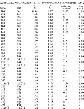
end-centered on (100)0 .TABLE II
LAUE DATA FROM U02(N0.1)2.6II20; PnoTOGRAl'H No. 8, THROUGH (lOO)a
H1' d J!stimated S for
(hkl>a (hkl)
A.
A.
intensity'' ft 0.13104 041 0.44 1.97 0.05 1.25
ll4 l41 A3 1 .94 a lJ
162 621 .45 1.89 8 9.98
124 241 .42 1.88 0.25 1.25
124 241 .38 l.88 .25 1.25
153
5:n
.38 l.84 3.5 6.37171 711 .45 1.79 2.5 7.29
144 441 .35
um
0.05 1.25163 fi31 .40 1.fi7 a 0
ISO 801 .39 1.62 a 0
182 821 .37 1.51 3.5 9.98
182 821 .41 1.51 3.5 9.98
191 ~11 ."J7 1.42 1.3 7.29
rnT
~fll .44 1.42 1.2 7.29183 831 .37 1.39 a 0
155 551 .43 1.35 1 .4 8.09
1.10.0 10.0.1 .35 1.30 a 0
126 261 .44 1.29 1.5 9.82
l.10 .T 10 .T. l .36 1.29 a 0
165 K51 .39 1.28 a 0
193 931 .39 1.27 0.8 6.37
136 361 .41 1.27 a 0
184 841 .40 1.26 a 1.25
265 652 .40 1.26 a 0
1.10.2 10.2.l .36 1.24 l.& 9.98
146 iHj] .38 1.23 1.8 9.82
116 401 .42 1.23 1.8 9.82
175
t51
.39 1.21 0.9 8.09275 752 .41 1.19 .6 5.88
275 752 .35 1.19 .7 5.88
156 561 .39 1.18 a 0
194 941 .36 1.17 a ()
July, 1924 STRUCTURE OF URANYL NITRATE 1619
TABLE II (Concluded)
nl\ d E.5tittLa.tcd S fu1
(hkl)a (hkl) A. A. i:otensity" u =; D.13
185 851 .35 1.14 a 0
166 661 .36 1.13 1.6 9.82
117 171 .36 1.13 0.35 5.3-0
285 852 .37 1.12 a 0
2.11.2 11.2.2 .36 1.12 a 0
137 371 .35 1.10 0.2 5.36
2.II.3 11.3.2 .42 1.07 .6 7.71
295 952 .45 1.06 .25 5.88
357 573 .41 1.01 .25 5.36
2.13.I 13.I.2 .39 0.99 .2 6.85
367 673 .41 .98 a 0
2.13.2 13 .2.2 .39 .97 a 0
377 773 .38 .94 0.15 5.36
2.11.5 11.5.2 .35 .94 .15 5.88
2.13.3 13.3.2 .37 .93 .15 7.71
3 .12 .4 12 .4 .3 .37 .93 a 1.25
3 .14.0 14.0.3 .46 .91 a 0
3.10.6 10.6.3 .38 .91 0.35 9.82
3.14.2 14.2.3 .40 .89 .2 9.98
a a ·signifies absent.
Discussion of Previous Conclusions
The complete absence of all odd orders of reflection from the pinacoids (Table I) makes it <lifficull to interpret any of Clark's2 peaks as
first-order reflections from these faces. Moreover, as shown above, the Laue photographic data definitely show that the underlying lattice is the end-cenlere<l one; aml lhis again nect:ssitales Lhe al>::;enct: of o<l<l ortlers of re-flection from two pinacoids. This makes it clear that at least some of the peaks observed by Clark did not arise from the excitation of the L-radialion of uranium witldu the crystal awl it::; reflection by the pinacoids; for, as shown in the introduction, this explanation would necessitate in-terpreting some of the peaks as first-order reflections. The belief that5 "the unil parallduvipetl ... is face-ct:nlt:retl" is, mureuver, nuL :.ml>-stantiated by the work described in this paper. It is evident that for purposes of crystal structure analysis further investigation of the phenom-enun repmlt:tl l>y Clark antl Duane6 is tlt::::>iralJle.
The Space Group
The holohedral space groups derived from the lattice
r
0 ' are7 Vh17,Vi
118, Vh19
, Vh20,
Viz:21,
Vh22• Some of these may be definitely excluded5 Ref. 2, p. 384.
6 Clark and Duane, J. Opt. Soc., 7, 455 (1923).
7 Wyckoff, "The Analytical Expression of the Results of the Theory of
1620 LINUS PAULING AND ROSCOE G. DICKINSON Vol. 46
by a consideration of reflections from 1;rism planes. 8 Prism planes having h.
+
k+
l even cannot reflect in the first order if the space group fo V1118, Vh21, or V,122; those having h + k
+
l odd cannot reflect in the first orderif the space group is F;,~0 or Vh22
• The presence of reflections of both of
thesP types, as shown in 'rable III, definitely eliminates all of these space groups. Of the rcmaini11g two space groups Vh17 and Vh19 the former
permits first-order reflections from planes of only two prism zones, while the latter permits such reflections from ail three. No first-order reflections from planes of the type (hk:O)G were observed on any photograph, although a number of such planes were in positions favorable to reflection. The evidence is thus in favor9 of
ViP
as opposed tov,p.
For convenience in applying the theory of space groups, and in comparing structures with each other, it is desirable to assign the axes in agree-ment with the conventio11s adopted during the developagree-ment of the theory of space groups. 1'he coordinates of equivalent positions for V1,11
as tabulated7 require that no first-order reflections take place from planes withh k odd or with k 0. If the axes of U02(N03)2.6H20 be chosen such that d100 = 13.H5, do10 = 8.02, and do01 = 11.42
A.,
the structure willbe in agreement with this tabulation. 1'he transformation from indices (hkl)0 to those (hkl) conforming with space group usage is hG
=
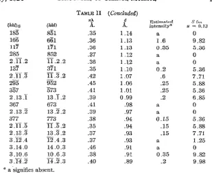
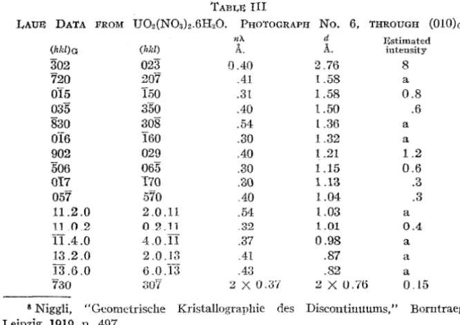
l, k0 = h, and l0 = k.TABLE III
LAUE DATA FROM U02(NOs)z.6H20. PHOTOGRAPH No. 6, 'THROUGH (OlO)a
nA. d I~stimated
(hld)a (hkl) A. A. intensity
302 023 () .40 2.76 8
720 207 .41 t.58 a
015 150 .31 1.58 0.8
035 350 .40 l.50 .6
830 308 .54 l.36 a
OT6 l60 .30 1.32 a
902 029 .40 1.21 1.2
506 065 .30 1.15 0.6
OI7 170 .30 1.13 .3
057 570 AO 1.04 .3
11.2 .0 2.0.11 .54 1.03 a
11 0.2 0 .2.11 .32 1.01 0.4
II .4.0 4.0.11 .37 0.98 a
13.2.0 2 .0.13 .41 .87 a
13.6.0 6.0.13 .43 .82 a
730 307 2X0.3'/ 2 X U.76 O. l5
8 Niggli, "Gcom.etrische Kristallographie des Disco11ti11ttums," Borntraeger,
Leipzig, 1919, p. 497.
9 The absence of all odd orders of reflection from the three pinacoids is further evi-dence in favor of V h11; for Vh19 can give odd orders of reflection from one pinacoid while
July, 1924 STRUCTURE Oli' URANYL, NITRATE 1621
The Arrangement of the Uranium Atoms
In view of the large number of parameters involved, it seems at present impracticable to attempt a determination of the positions of all of the atoms in the unit of structure. However, information can be obtained concern-ing the positions of the uranium atoms. Uranium has the atomic number 92; the sum of the atomic numbers of the other atoms in U0
2-(N03)2.6H20 is 138 .and the highest of these is 8. Consequently, especially
in:~the~case of planes having complicated indices and small interplanar distances, the intensity of reflection may be expected to be governed largely by the positions of the uraniu.m atoms. ·We have, indeed, found it possible to assign positions to the uranium atoms which give a very consistent agreement between the general character of the observed in-tensities and the structure factors S calculated, neglecting all atoms but those of uranium.
'I'here are the threeifollowing ways of arranging the four uranium atoms in a unit with the [space-group symmetry
Vh
17: (a) 000, OOt,!
!O,10
~..----''"---lL---'t'---~L---"i--~~""'-~~-¥---"'--~~-"'!
.OS .10 t,! .15 .20 .25
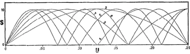
Fig. 1.-Values of S calculated for Arrangement c, with
4U
= 10. The r11rvPs :uP. for pl::i.ne<: of Class 1, the number on the curve being the value of k.The curves also give values of S for planes of Class 2 with these values of kif
u is made 0.25 at the left and 0 at the right of the figure.
!!!;
(b) !OO, !O~, O!O, OH; (c) Ou!,Out
H
+
ut,
H -
u£.
If the uranium atoms alone are considered, and these without reference to their own symmetry, then (a) differs from (b) only by a translation of the whole structure along the H-axis, and (c) with u=
0 differs from (a) or (b) only by a translation of the whole structtire; hence, in the present case, (a) and (b) are included in (c) and only the last need be considered. For first-order reflections (c) gives: A=
4U
cos 27r(uk+
l/4); B=
0. In Fig. 1 are curves giving values of S=
v
A 2+
B2 for anumber of planes plotted against u from u
=
0 to u=
0.25; this interval includes all distinct arrangements of the uranium atoms. The planes are divided into two classes: (1) those with l odd, and (2) those with leven. All planes of a given class with the same value of k have the same structure factor.
1622 I.,INUS PAUI.,ING AND ROSCO:& G. DICKINSON Vol. 46
!?. = G reflected comparatively strongly. The structure factor due to the uranium atoms (Fig. 1) is in agreement with these facts only in the neigh-borhood of u = 0.125. A consideration of the reflections from other planes
indicates for u a value near 0.13.
T
Values of this structure factor for all planes of Table III area.02 given in the 6th column. By
1
comparing these values with the observed intensities it will be_.-'-""""!-~--,r--r---:::1t--~-t--:7
l
. 11.42--1
l'---13.l&l ~
Fig. 2.-The arrangement of the uranium atoms in the unit of structure of uranyl nitrate hexahydrate, U02(N03)a.6H20.
value of u is altered by as much as 0.01 de:>Lruyed.
seen that this arrangement of
the uranium atoms alum~ wiU1 u 0.13 accounts satisfactorily for most of the abnormalities in
inlensity relations, and for all of the pronounced ones. If this the agreement is in many cases
This arrangement of the uranium atoms in the unit of structure is shown in Fig. 2.
Summary
Crystals of uranyl nitrate hexahydrate, U02(NOa)2.6H20, have been investigated, using both spectral photographs of the molybdenum K-radiation and Laue photographs, and the data have been interpreted with the aid of the theory of space groups. The unit of structure, which con-tains four U02(NOa)2.6H20, has d100 = 13.15, do10 = 8.02, and do01 = 11.42
A.,
and is end centered on (001). The data indicate that the space-group symmetry is Vh17, and that the uranium atoms are at (Ou!) (Ou!)CH
+it
!)(H -
it !) with it - 0.13. Referred to the axes used byGroth, 1 the above-mentioned interplanar distances are for the planes (OlO)c,
(OOl)c, and (100)0 , respectively.
1'hesc results make unjustifiable Clark's interpretation?. of his observed
peaks as due to a characteristic radiation of the uranium atoms reflected by the pinacoids.
1Reprinrcd from t11e Journal of the American Chemical ;';ociety, Vol. XI.VI, No. 12. December, 1924. J
(CONTRIBUTION FROM THE GATES CHEMICAL LABORATORY, CALIFORNIA INSTITUTE OF TECHNOLOGY, No. 4\J]
THE CRYSTAL STRUCTURES OF AMMONIUM FLUOFERRATE, FLUO-ALUMINATE AND OXYFLUOMOLYBDATE
BY LINUS PAULING
RSCEIVED SUPTEMBER 0, 1924 Pum,rSHUD Dr:C!lMBllR 13. 1924 Introduction
Crystals of ammonium :fluo-aluminate (NH4)aAIF, :fluotitanate (NH4)a-TiF6, :fluovanadate (NH4)aVF6, :fluochromate (NH4)aCrFs and fluo-fe11al1:: (NH4) 3FeF6, are described by Groth1 as apparently isomorphous,
optically isotropic octahedra. Ammonium oxy:fluomolybdate (NH4)s-MoOaF a and oxy:fluotungstate \NH4)3 WOaF3, are also described2 as forming similar small isotropic octahedra. The structures of ammonium chloro-platinate3 (NH4)2PtCl6, chlorostannate4 (NH4)2SnC16 and :fluosilicate5
(NH4)2SiF6, have been determined; it seemed of interest to investigate these complex :fluorides for the purpose of finding, if possible, the changes in structure produced by the introduction of a third ammonium group. Moreover, the effect of replacing three of the six halogen atoms by oxygen could not be confidently predicted and it was thought that a study of these oxyfiuorides also was desirable.
Crystals of ammonium :fluoferrate were obtained by the slow evapora-tion of a soluevapora-tion of ammonium :fluoride and ferric chloride. The light yellow crystals, less than 0.8 mm. on an edge, were found on analysis to contain only ammonia, iron and fluorine. Transparent plates of ammonium fluo a1uminate as large as 4 or 5 mm. on an edge were ob-tained similarly from a solution of ammonium fluoride and aluminum chloride and were also found to be free from impurities. Brilliant white crystals of ammonium oxy:fluomolybdate about 1 mm. in diameter re-sulted from the slow evaporation of a solution of molybdic acid, ammonium hydroxide and ammonium fluoride. The crystals of all three substances were observed to be optically isotropic and to show the form { 111} ; subsidiary faces of ( 100
l
were in some cases developed by ammonium :fluo-aluminate.Spectral, Laue and powder photographs were used in this investiga-tion, the data so obtained being interpreted with the aid of the theory of space groups. 6 Spectral photographs of the K-radiation of molyb-denum were made either by reflection from a developed face of the
ro-1 Groth, "Chemische Krystallographie," Engelmann, Leipzig, 1906, vol. 1, p. 416. 2 Ref. 1, p. 586.
3 Wyf'koff ,:inn Po~nj<ik, 'rm,; JOURNAL, 43, 2292 (1921). 4 Dickinson, ibid., 44, 276 (1922).
6 Bozarth, ibid., 44, 1066 (1922).
Dec., 1Q24 S'l'RUC'l'UR~S OF AMMONIUM FI.UO SALTS 2739
tating crystal or, for small specimens, by reflection during the transmis-sion of the beam through the crystal. Laue photographs were made with a tube with a tungsten anticathode operated at a peak voltage of 52,000 v., so that the minimum wave length of X-rays incident on the crystal was about 0.24
A.
The planes producing the Laue spots were identified with the aid of gnomonic projections. Powder photographs were made with an apparatus similar to that described by Davey, 7 using a molybdenum tube and having a zirconia filter directly in front of the film. 1'he investigation was aided financially from a grant made to Professor A. A. Noyes by the Carnegie Institution of Washington. I wish to thank also Dr. Roscoe G. Dickinson for the use of apparatus designed by him and for personal assistance during the research.The Structure of Ammonium Fluoferrate
111 Table I are given data for ammonium fluofcrratc leading to the value 4.55
A.
for d100/n. It was found that in order to account for theOrder of reflection
TABI,E I
SPECTRA!, DATA FROM (100) Ul•' (NH4)aFeF6
Angle of reflection
dioo/n
A. I•;stimated intensityb
n fJ 3° 59.3' 4.53 m
n a 4 28 4.56 s
2n fJ 7 58 4.55 m
2n a 8 57. 7 4. 56 s
3n B 11 59 4.56 vw
3n a 13 32.7 4.55 mw
a The symbol fJ denotes in this and subsequent tables the line MoKp (0.6311 A.);
the symbol a, the line MoKa (0.710
A.).
.
b Abbreviations used for all spectral intensities in this paper are: vs, very strong; s, strong; ms, medium strong; m, medium; mw, medium weak; w, weak; vw, very weak; a, absent.
production of the observed Laue reflections shown in ~fable II by means of X-rays present in the incident beam it would be necessary to place n = 2. No reflections remained unaccounted for by such a unit with d10o = Y.10
A.,
which may accordingly be accepted as the correct one. This unit contains 4 (NH4)3FeF6, corresponding to a calculated density of 1.96 g./cc. ~rhe density of a sample of precipitated ammonium fluo-ferrate obtained by pouring together solutions of ammonium fluoride and ferric chloride was found by means of a pycnometer with benzene to be 1.91. A powder photograph of this sample showed weak lines of ammonium chloride, the presence of which explains the slight disagree-ment in the densities. The value 9.10A.
for d100 was verified by the pow-der photographic data, which are not given because they did not aid in determining the structure.2710 LINUS rAUI,ING Vol. 40
TABI,~ II
LAUS PHOTOGRAPJ:llC DATA FRO!ll (NH4)~FeFo
dhkz ti'/. Estimated S for
hkl A.
A.
intensity u =0.21Photograph No. 2, through (110) 104 2Xl.10 2
x
0.45 0.3 0.76;,71 1.0iJ .44 .4 1.28
Photograph No. :1, through (UO) 014 2Xl.10 2X .39 .05 . 0. 7fi
322 2Xl.10 2X .39 .15 2.07
Photograph No. cl, through (111) 517 l .Oi) .44 .3 1.28
7;)f) 1.00 .44 .25 0.34
717
o.m
.39 .15 0.66:I.JO 2
x
.91 2x
.38 .20 1.57jf;g .88 .44 .25 3 .03
93·5 .85 .39 .15 2.09
432 2X .84 2X .42 .10 1.10
25T 2X .83 2X .42 .20 3.08
577 .82 .41 .08 0.0'1
'i91 .80 .40 .04 1.10
114 2X . 7!) 2X .41 .06 0.67
433 2X .78 2X .41 .10 2.06
o:~.-. 2X .78 2X .41 . 15 4.36
No Laue spots correspond to first-order refleclions except those from planes with all indices odd; this indicates that the arrangement of the atoms (with the possible exception of those of hydrogen) is based on a face-centered lattice. The coordinates of the positions of 12 N, 4 Fe, and 24 F for the only arrangements fulfilling these conditions a1e8 a~
follows.
From space groups '!'~, 0\ or O~
4 Fe or 4 Nat 4(b): UOU; ~W; W!i-; U!J'·j-4 Nor U!J'·j-4 Fe at 4(c): HL WO; O~O; 00}
8 Nat S(e): H!; l~L '1U; Ht; HL U!; UL HJ
241•' at 24(a): uOO; u -I· l, -~ O: u +-.\: 0 -.\:: uH; uOO; -& - u /; O: il- - u o ~; uH; OuO; } u
+
~ 0; -~ n 1; 0 tt+
! ~; OilO; t 1- - 11 0; ~ O ! ; 0 1 - u t;OOu; ~ ! u; ! 0 u
+
~; 0} u+
!; 00i1; ~ } il; ! 0 ~ u; 0 ! ~ - u or at 24(c): HO; HO; ;!O; HO; 0!1; UH; OH; OH; }O}; !O}; Wi; !OL HL H!;~1i; -}~~; l~l; iJl; l~:L li~, ~4·~·, :1l~~ 11-~, til
From space-groups '1'2 or TJ 4 N or 4 Fe at 4(b)
4 N or 4 Fe at 4(c)
4 Nor 4. Fe al 4(d): !U; l U;
4 Nor 4 Fe at 4(e): UL HL !~L lU
24 Fat 24(a) or ut 24(b): Uu; ft{~; u +} ~ !; i} - u i; Hu; uU; li -- u l f;
l u
+
! ~; Hu; tul; ! - ut };
i l u+
i;
Hu; iui; u+
! t !; ~£} -
u; uH;!ui;
i u+
! i;H l -
u; uH; ~n~; }t
u t;ti
u+ {
Dec., 1924 STRUCTURES OF AMMONIUM FLUO SALTS 2741
It will be noticed that no arrangement is possible in which all of the nitro-gen atoms are in equivalent positions.
Any arrangement with the fluorine atoms at 24(c) will give the same structure factor to all first-order reflections from planes with all indices odd. The observation that, for example, { 951 j reflects more strongly than { 771} at the same wave length despite its smaller interplanar dis-tance accordingly eliminates this. The arrangement with Fe at 4(d), N ::i.t 4(h), 4(1'), ::imi 4(e), and F at 24(a) places six fluorine atoms at octahedron corners around an atom of nitrogen rather than one of iron. The chemical improbability of this structure provides considerable reason for not giving it further consideration; however, it w::is found possible to eliminate it definitely by means of X-ray data. It can be shown that, if this be the structure of the substance, the spectral data from (111) re-rinirP th::it the p:::ir:;imeter 11 sho11ld lie in the rPgion between 0.20 And 0.30 Throughout this region the structure factor for { 410} (n 2) is greater than that for {322} (n 2), except at u 0.25, where they are equal. 'I'hP PXpt>.rlmPnfal ohsPrv::ition th::it { :~?.2} reftPC'ts mnf'h mon" strongly than { 410} accordingly makes this structure impossible. The only re-maining distinct arrangement can be derived from space groups T2 or
T~ by placing Fe at 4(b), N at 4(c), 4(d), and 4(e), and F at 24(a), or from T~, 03, or
ot
by placing Nat 8(e) instead of at 4(d) and 4(e).Planes giving useful Laue reflections can be divided into three classes. These are, with corresponding values of the structure factor S, the fol-lowing.
Class 1; all indices odd: n = 1, S = 4Fe - 4N + 8F (cos 2iruh +cos 2iruk +
cos 2?rul)
Class 2; two indices odd, one even: n 1, S O; n 2, S 4Fe + 12N + 8F (cos 41111h + cos 41111k + cos 4irul)
Class 3; one index odd, two even: n = 1, S = O; n = 2, S 4Fe - 4N + 8F (cos 47fuh
+
cos 47fuk + cos 47rul)Comparison may be made, it will be seen, between planes in each class and between those of Classes 1 and 3 (n
=
2) with only qualitative as-sumptions regarding relative reflecting powers; care must be used with planes with small values of S.A spectral photograph from (Ill) showed five orders of reflection, with intensities strong, medium, weak, medium and weak. This shows that the structure factor is greater for n
=
4 than for n = 2, and greater forn
=
5 than for n=
3. Curves of these structure factors are shown in Fig. 1 for u=
0 to u=
0.50, which includes all distinct structures. In their calculation relative reflecting powers of different atoms have been assumed proportional to their atomic numbers; however, a considerable deviation from this would not invalidate the arguments given here. It2742 LINUS l'AULING Vol. 46
about 0.16 and 0.25. Similarly calculated curves of the structure-factors of somP 11sPfnl planps rt>ilPcting on Lam~ photographs for a rangP of values
0.0 .10 .2()
u
.30 .40 .50Fig. 1.-Structure-factor cur•ves for (111). The order of reflection is given by the numbers on the curves. Positive values of S are to be read both above and below the horizontal lines, which have the value S=O for the substances indicated.
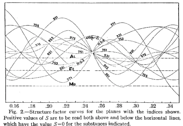
of u are given in Fig. 2. It was observed that { 751} gave a stronger re-flection than {410} (n = 2), requiring u to be less than 0.217, and that
.18 .20 .22 .32 .34
Fig. 2.-Structure-factor curves for the planes with the indices shown. Positive values of S are to be read both above and below the horizontal lines, which have the value S=O for the substances indicated.
{953}, with considerably smaller interplanar distance, gave as strong a
Dec., 1924 STRUCTURES OF AMMONIUM FI,UO SALTS 2743
limitation of possible values of u was not accomplished; values of S for u 0.21, which seems to be the most probable value, are given in Table II for comparison with the observed Laue intensities; the agreement is good, except for a few planes for which S would be considerably affected by a small change in the relative reflecting powers of different atoms.
Chemical evidence strongly indicates that each nitrogen atom is sur-rounded by 4 hydrogen atoms. Space groups T2 and Ta provide the uuly way in which this can be accomplished. Hy assigning ditrerent values to the parameter v in 16(a), with coordinates,
vvv; v
+
t
v+
t
v; v+
! v v+
L v v+
t v+
t; vvv; v+}} -
v v; v+
t
v ! v; v ~ v} - v; vvv;} v v + ~ v;} - v vt -
v; v v +}} - v; vvv; t - vt -
v v;t -
v v v+ };
v t -
v v+}
the 48 hydrogen atoms can be placed in such a way that each nitrogen atom is surrounded tetrahedrally by 4 hydrogen atoms. A probable arrangement of the hydrogen atoms results on giving v values of! - d,
~ d, and ~ d, in which d is the hydrogen-to-nitrogen distance; these positions are indicated by the corners of the tetrahedra in Fig. 4.
The Structure of Ammonium Fluo-aluminate
Spectral data for ammonium fiuo-aluminate, given in 'fable III, show
d111
/n
to be 4.85A.
Ifn
were 1, the unit of structure would have d100 =8.40
A.,
and would contain 4(NH4)3AlF5. 'the calculated density 2.17 g./ee. is somewhat greater than 2.02, the value detennined by a sus-pension method on small crystals, which showed considerable variation among themselves.TABI,~ III
SPnC'l'RAL DA'l'A FROM (111) OF (NH4)sAlFs
Order of Angle of dm/n Estimated
reflection Line reflection A. intensity
n {3 3° 43.61 4.856 ms
n a 4 11.5 4.861 vs
2n {3 7 29 4.845 ms
2n 8 25.5 4.847 v:>
3n {3 11 15.3 4.846 vw
3n a 12 40.6 4.851 mw
4n {3 15 6.5 4.844 vw
4n a 17 0 4.855 mw
2744 LINUS PAULING Vol. 46
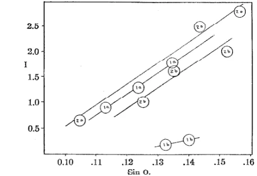
{ 13.11.5} ( { 531) on the twin) on two Laue photographs taken with crystals prepared at different times. It will be seen that there is pronounced disagreement, definitely indicating twinning. (2) All of the 20 lines observed on a powder photograph of the substance (Table IV) are ac-counted for by the small unit; th,csc photographs arc not influenced by twinning. The absence of any reflections requiring a larger unit makes it improbable that such a unit exists. (3) Only a few very complicated forms such as {25.17.7} gave low values of n}... If indices (h'k'l') based on the axes of the twin are calculated by means of the equations9 h' =
2l 2k h, k'
=
2h+
2l - k, and l'=
2h+
2k - l, no reflections re-main unexplained by the small unit. Moreover, the ratio of intensities2.5
2.0
I
1.5
1.0
0.5
0.10 .11 .12 .13 .14 .15 .16
Sin o.
Fig. 3.-Relative intensities of reflection of 531; la and lb are for the two individuals composing one twinned crystal of (NH4)aAlF6 and 2a and 2b for another twinned crystal.
from the two individuals composing the twinned crystal whenever it can be determined is found to be about 8: 1 for one crystal and 8: 6 for the other.
These indications were accepted as showing the unit of structure to be the small one with 4(NH4) 3AlF6. It was found that some Laue spots were produced by the simultaneous reflection from one plane in one in-dividual of the twinned crystal and from another in the other: In many cases, however, no reflection could occur from onf' of the two pfanf'!'l because wave lengths shorter than 0.24
A.
would have been required. These planes, free from ambiguity, could be compared with each other in the usual way. Only planes with all indices odd gave first-order re-flections. Abnormal intensity relations occurred, eliminating anyDec., 1924 S'l'KUC'J.'UK.l!;::S U.l•' AMMONIUM FLUU SAl/fS 2745
TABr..E IV
Powm{R Puo'l'OORAPRIC DA'l'A ll'ROM (NH,).AlF0 ; d10o = 8.40 A.
dhkl calculated di.kl observed Estimated co opera ting Number of S for
hkl" A.
A.
intensity planes u 0.197111 4.85 4.9 6 8 1.32
200 4.20 4.20 4 6 1.55
220 2.969 2.96 3 12 1.31
311 2.535 2.53 1.5 24 0.15
222 2.423 2.42 Fi ~ ?. 03
400 2.100 2.10 6 6 4.13
331 1.928 1.93 0.1 24 1.02
420 1.879 1.875 .2 24 0.78
422 1.717 1.720 .05 24 .55
333, 511 1.619 1.616 5 8,24 2.19, Ul8
440 1.485 1.481 3 12 3.36
531 1.420 1.421 2 48 0.82
442,600 1.400 24, 6 .02, 2. 75
620 1.329 1.326 1 24 2.52
533 1.281 24 0.35
f\22 l.269 1.269 0.05 24 .82
4:44 1.213 1.210 0.1 8 2.60
711, 551 1.189 1.175 2 24, 24 0.26, 2.65
640 1.166 1.161 0.2-0.4 24. 1.99
642 1.123 1.120 1 48 1.75
731, 553 1.093 1.094 1 48, 24 0.91, 1.49
800 1.050 6 3.00
733 1.028 24 2.08
820,644 1.020 24,24 0.34, 1.22
822,660 0.991 0.985 0.2 24, 12 .58, 3.72 555,751 .970 0.970 0.5 8, 48 3.32, 0.93
662 .964 24 0.37
840 .940 .940 0.2 24 2.24
911, 753 .922 24,48 1.13, 0.24
842 .916 48 1.ll
564 .895 .894 0.2 24 2.96
" In this table the second order of (211) is written (422), and similarly for all orders.
ture with F at 24(c); the second improbable arrangement was not elimi-nated by X-ray data on account of the similarity in reflecting powers of Al and N.
The value of u in the remaining arrangement can be closely limited.
The spectral data show the structure-factor for n = 2 from (111) to be
greater than for n
=
1 and for n=
4 greater than for n 3. Thepara-meter u is accordingly limited to the region between 0.16 and 0.30 and that between 0.42 and 0.50. The latter can be eliminated by means of
Laue data. Laue data from the two crystals for which the intensity
ratios of twins are about 8:1 and 8:6 are given in Table V. Among the
unambiguous intensity relations are these: \953\
>>
\753}, requiring2746 LINUS PAULING Vol. 46
be less than 0.200. It will be observed that (531} reflected much more strongly than { 331}, indicating the true position of the line S = 0 to be somewhat lower than drawn in Fig. 2 (corresponding to a greater re-:fleeting power for Al). With this knowledge, the relation ( 931}
> (
753} places u above 0.194. The most probable value for u is 0.197; the com-plete agreement of this structure with the experimental data can be seen by reference to Tables IV and V. It is necessary to mention thatl'ABLE V
LAUE PHO'I'OGRAPHIC DA'I'A FROM (NH4)aAIF6, THROUGH (111) CRYS'I'AL No. 1; INTENSITY RATIO 011Twrns8:1
Estimated dhkl nX S for dh'k'I' n'X' S for
intensity hkl A.
A.
u=0.197 h'k'l'A.
A.. u~0.1970.8 331 1.92 0.35 1.02 7.11.I 0.64 0.12
. \) 315 1.12 .32 0.82 11.5.13 .17 .11
1.3 153 1.42 .35 .82 5.13.11 .47 .12
1.8 351 1.42 .38 .82 11.13.5 .47 .13
0.05 221 2
x
1.40 2x
.43 .02 481 2x
.47 2x
.14 1.2 032 2x
1.16 2x
.42 1.99 278 2x
.39 2x
.14 0.05 341 2x
0.83 2x
.43 ·0.63 13.8.1 2x
.28 2x
.14.3 159 .81 .43 1.80 7.25.17 .27 .14
.2 13.5.11 .47 .12 513 1.42 .37 0.82
.3 13.11.5 .47 .13 531 1.42 .39 .82
CRYSTAL No. 2; IN'I'ENSI'I'Y RATIO 011 'fwrns 8:6; PHOTOGRAPH 1
0 A 18~ 1.92 0.34 1.02 I.11.7 0.64 0.11
.6 315 1.42 .29 0.82 11.5.13 .47 .10
2.5 153 1.42 .41 .82 5.13.11 .47 .14
2.8 351 1.42 .45 .82 11.13.5 .47 .15
0.2 533 1.28 .33 .3G 17.7.7 .43 .11
1.8 551 1.18 .32 2.65 17.13.I .39 .11
0.7 302 2
x
1.16 2x
.32 1.\)9 728 2x
.39 2x
.11.2 223 2
x
1.04 2x
.32 1.22 4.4.11 2x
.35 2x
.11.5 915 0.81 .32 1.80 17.7.25 .27 .11
.02 3.11.3 .71 .43 0.85 19.23.19 .24 .14 .06 11.1.5 .69 .43 2.16 19.11.29 .23 .14
.4 11.7.I .61 .10 331 1.92 .30 1.02
1.0 5.11.13 .47 .12 135 1.42 .35 0.82
1. 7 13.5.11 .47 .13 513 1.42 .38 .82
2.0 13.11.5 .47 .14 531 1.42 .43 .82
0.03 814 2
x
.47 2x
.15 2rn 2x
1.40 2x
.45 .02.7 I.17.13 .39 .10 155 1.18 .29 2.65
.3 25.7.17 .27 .15 519 0.81 .44 1.80
CRYSTAL, Nv. 2; PHv'fVGKAl:'H 2
0.05 375 0.92 0.42 0.24 1.11.25 0.31 0.14
.4 931 .88 .42 .04 17.19.13 .29 .14
.5 935 .78 .43 .63 13.5.29 .26 .14
.06 11.3.I .73 .45 .32 19.23.17 .24 .15
.05 975 .68 .44 .75 I3.35.I .23 .15
Dec., 1924 STRUCTURES OF AMMONIUM FLUO SALTS 2747
an increase in the relative reflecting power of Al will increase S for some planes and decrease it for others.
After the structure of (NH4)3AlD\ had been determined, a crystal showing re-entrant angles was found. This crystal was shown by gonio-metric measurements to be twinned with (111) as twinning plane and composition plane. Sections of each of the two individuals were made parallel to the twinning plane by cleaving; Laue photographs of these sections showed the crystal axes to correspond to the twinning described above. Moreover, no reflections requiring the larger unit were produced
by either individual. The data from these photographs were in agreement with the structure deduced above. Subsequent careful examination of the face development of the small crystal giving photographs with the 8: 6 intensity ratio showed it to consist of two individuals twinned on (111); their thicknesses were in the same ratio, about 8: 6.
The Structure of Ammonium Oxyfluomolybdate
Spectral data for ammonium oxyfluomolybdate, given in Table VI, place dm/n equal to 5.25
A.
If n is 1, the unit of structure has d100=
9.10A.
No reflections were found on any of three Laue photographs which required a larger unit (on each photograph there were a few scat tered spots close to the central image to which it was difficult to assign indices; these were explained as produced by a crystal fragment with an orientation different from that of the main crystal). '!'he density calcu-lated from the X-ray data, assigning four molecules to the unit, is 2.23 g./ cc.; a direct determination by means of a pycnometer of the density of a liquid in which a small crystal remained suspended gave the value 2.28.TABL:S VI
SPEC'J'RA:t. DATA FROM (111) 01' (NH4).Mo00P\
Order of Angle of dm/n Estimated
reflection Line reflection A. intensity
n fl 3° 26' 5.26 ms
n a 3 53 5.25 vs
2n a
3n a 11 44 5.24 vw
4n a 15 41 5.25 w
No planes were observed to give first-order reflections except those with all indices odd, indicating that the structure is based on a face-centered lattice. However, there are no arrangements of 4 Mo, 12 N, 12 0 and 12 F based on this lattice, 8 nor any which are approximately face-centered.
2748 LINUS PAULING Vol. 46
reflection from (111) would require that u be between 0.20 and 0.30. Throughout this region the structure factor for
!
551) is over twice as great as that for { 320} (n 2); the observation that the two forms reflect with about equal intensity accordingly eliminates this structure.The spectral intensities from (111) limit the possible values of u for the third arrangement to the region between 0.15 and 0.30, with indica-tions of a value near 0.20. The form { 951} reflected on Laue photographs as strongly as
l
755}, despite its smaller interplanar distance; this limitsu to between 0.194 and 0.25 and the further observation that {755) re-flected more strongly than { 931} shows u to be less than 0.220. The values of S given in Table VII are calculated for u 0.21.
TABLE: VII
LAUE PHOTOGRAPHIC DATA FROM (NH4)3Mo03Fa, THROUGH (111)
dhM. 11h Estimated S for
hid A. A. intensity u 0.21
551 1.2'/ 0.28 0.20 4.09
023 2 x 1.26 2X .28 .20 3.42
537 l.00 .41 .08 1.23
139 0.95 .37 .04 2.28
557 .91 .38 .05 2.86
57G .91 .::19 .05 2.86
159 .88 .41 .05 3.92
377 .88 .33 a 0.70
593 .85 .34 .04 2.98
Discussion of the Structures
The arrangement of the atoms in the units of structure of ammonium fluofcrratc, fluo-alum.inatc and oxyfluomolybdute is shown in Fig. 4.
0
M
.0
="
0-1.o_f"'>
o F.0
~
9 Fe.Al.Mo
Fig. 4.-The arrangement of atoms in the units of structure of (NH 1),Fd<\, (NH,)"AlFo and (NH,)"MoO:iF3.
This arrangement is the same as that of ammonium