Design and Experimental Validation of MIMO Multiuser
Detection for Downlink Packet Data
Dragan Samardzija
Bell Laboratories, Lucent Technologies, Holmdel, NJ 07733, USA Email:[email protected]
Angel Lozano
Bell Laboratories, Lucent Technologies, Holmdel, NJ 07733, USA Email:[email protected]
Constantinos B. Papadias
Bell Laboratories, Lucent Technologies, Holmdel, NJ 07733, USA Email:[email protected]
Received 8 March 2004; Revised 29 October 2004
In single-user MIMO communication, the first-order throughput scaling is determined by the smallest of the number of transmit and receive antennas. This typically renders terminals the constraining bottleneck. In a multiuser downlink, this bottleneck can be bypassed by having the base station communicate with multiple terminals simultaneously, in which case the receive antennas at those terminals are effectively pooled in terms of the capacity scaling. This, however, requires that the base have instantaneous channel information. Without such information, the structure and statistics of the channel can be exploited to form multiple simultaneous beams towards the various users, but these beams are in general mutually interfering. This paper proposes the use of multiuser detection to discriminate the signals conveyed over interfering beams. This approach is formulated and experimentally evaluated on an HSDPA MIMO testbed that involves a commercial base station, multiantenna terminals, and custom ASICs.
Keywords and phrases:MIMO, HSDPA, UMTS, experimental validation.
1. INTRODUCTION
MIMO (multiple-input multiple-output) schemes utilizing multiple transmit and receive antennas are posed to be a major ingredient in the evolutionary process of wireless communication. Widely recognized features associated with MIMO are spatial diversity, signal enhancements, interfer-ence mitigation, and spatial multiplexing. The latter, in par-ticular, has driven a lot of the research over the last decade, ever since it was shown in [1,2] that—in adequate channel conditions—the ergodic capacity (in bps/Hz) of a MIMO link as function of the average SNR (signal-to-noise ratio) behaves as
C(SNR)=minnT,nRlog2SNR +O(1), (1)
wherenTandnRdenote the numbers of transmit and receive antennas, respectively. This linear scaling with the number of antennas is a powerful means to achieve high spectral utiliza-tion provided that antenna arrays can be effectively deployed. In actual wireless systems, of course, links do not oper-ate in isolation: each base station must actively communicoper-ate
with a plurality of users and thus a number of MIMO links have to coexist. The behavior expressed by (1) can be im-mediately translated onto a multiuser environment by parti-tioning either time or frequency onto orthogonal sets, each of which is assigned to a particular user link. Focusing on the downlink, wherenTindicates the number of transmit an-tennas at the base station whilenRrepresents the number of receive antennas at the terminal, such orthogonal multiplex-ing incurs only a small loss in capacity ifnR nT. Unfor-tunately, the small size and cost sensitivity of mobile termi-nals precludes the deployment of a large number of antennas thereon and hence the most likely scenario for mobile sys-tems corresponds withnT ≥nR. (In some cases,nRmay be tightly restricted to equal 1.) In these conditions, orthogonal multiplexing severely constrains the capacity.
Without the constraint of time/frequency multiplexing, a downlink withnTantennas at the base andnRantennas at each ofKusers can yield a sum capacity that behaves as
whereby the tight restrictions onnRbecome immaterial and the burden of limiting the capacity shifts to the base station, wherenTcan be more easily scaled. Unfortunately, achieving (2) requires that the base station have accurate and instanta-neous information about the state of the fading channel be-tween each of its antennas and those at each of the mobiles [3,4,5,6]. This represents a total ofnT×K×nRtime-varying complex coefficients, whose instantaneous tracking by the base station is not a viable option in frequency-duplexed sys-tems.1
Without instantaneous channel state information at the transmitter, simultaneous transmission to multiple users be-comes challenging. In these conditions, interestingly, an-tenna correlation—often detrimental in MIMO—facilitates the formation of beams that can be directed to individual users providing partial isolation between their simultaneous transmissions. Moreover, this approach (already recognized and incorporated into the UMTS evolutionary process [7,8]) results in simple receiver structures. The degree of user isola-tion that can be attained through the composiisola-tion of beams, however, is directly determined by the location of the users in the cell and by the characteristics of their propagation chan-nels. UnlessK nT, every beam will often illuminate users other than the intended one resulting in significant levels of multiuser interference.
In this paper, we formulate and experimentally evalu-ate a scheme that provides resilience to strong multiuser in-terference when multiple beams are simultaneously active. The cornerstone of this scheme is the recognition that well-known MUD (multiuser techniques) [9], developed origi-nally for CDMA (code-division multiple access), can be ap-plied to the mitigation and removal of spatial interference. This represents, to some extent, an abandonment of the idea of simple and basically passive terminals and an embracing of the concept of smart terminals that actively participate in the task of discriminating transmissions to the different users. This conceptual shift is grounded on the rapid improvement in processing power that stems from Moore’s law.
In the remainder of the paper, we describe the MIMO-MUD scheme and we quantify its benefits through a series of experiments executed on a testbed that involves a com-mercial base station equipped with multiple antennas, ter-minals also equipped with multiple antennas, and specially designed MIMO ASICs (application-specific integrated cir-cuits). In order to render the experiments specific, the testbed is set up to comply with the HSDPA (high-speed downlink packet access) channel, which is foreseen to become the main vehicle for the provision of packet data in UMTS. To the best of our knowledge, these are the first such reported experi-ments.
1In time-duplexed systems, the reciprocity in the channel propagation characteristics makes it feasible to track these coefficients instantaneously as long as the Doppler spread is small enough. Note, however, that reciprocity does not necessarily apply to the transceivers and thus careful calibration may be required. Note also that the wide-area communication marketplace is currently dominated by frequency-duplexed systems.
The paper is organized as follows. Having justified the interest in the simultaneous transmission to multiple users through parallel beams, inSection 2, we review several well-known MUD approaches and discuss their applicability to the problem of mitigating the effects of multiuser interfer-ence across beams. InSection 3, in turn, we briefly describe the key features of UMTS HSDPA and describe in detail its implementation on the MIMO testbed platform. Finally,
Section 4 lays down a number of experimental results that validate the applicability of the chosen MIMO-MUD ap-proach.
2. MIMO-MUD: FORMULATION
Although not a requirement when MUD is used, we will limit the number of active users to beK ≤ nT, which allows for the generation of beams that are orthogonal in origin [10]. Larger numbers of users can of course be accommodated via time/frequency multiplexing.
The baseband complex linear model describing the com-munication between the base station and thekth terminal, k∈ {1,. . .,K}, is
yk=Hkx+nk, (3)
whereykis the (nR×1) vector received by terminalk,nkis
the corresponding additive white Gaussian noise vector with one-sided spectral density
N0=E
n2
nR , (4)
andHkis the (nR×nT) channel random matrix whose (i,j)th
entry represents the transfer coefficient2between thejth base transmit antenna and theith receive antenna at terminalk. In turn,xis the (nT×1) transmit vector, common to all users and structured as
x=
K
=1
ws, (5)
wheres is the information-bearing signal intended for
ter-minalwhile the vectorw contains the set of deterministic
coefficients that, applied to each of the transmit antennas, generate the corresponding beam. Without loss of general-ity, thew’s are chosen such thatw = 1,∈ {1,. . .,K},
and the power radiated for useris thenP =E[|s|2]. It is
important to point out that, without instantaneous channel information at the transmitter, the coefficients in the set of vectors w, ∈ {1,. . .,K}, cannot depend on the random
matricesH,∈ {1,. . .,K}, but only on their distributions.
From the standpoint of userk, we can conveniently rear-range (3) and (5) as
yk= H kwksk
signal intended for terminalk
+
=k
Hkws
interference + nk
noise
, (6)
where the interference corresponds to the signals that are being beamed towards terminals other than k, orthogonal in origin but—in general—not upon reception because of the random matrixHkwhose realization is unknown to the
transmitter. The realization of Hk, in contrast, is
consid-ered known to the receiver, which may estimate it provided, for example, that each individual beam is associated with a unique pilot. Multiple secondary pilots are already supported in UMTS [8] and are expected to be equally available in fu-ture system designs. More specifically, this enables receiverk to estimate the effective channelsHkwfor∈ {1,. . .,K}.
There are several manners in which the presence of the interference can be addressed.
(i) The simplest approach is to ignore the interference by matching the receiver at terminalkto the effective chan-nel for its desired signal generating the decision statistic (wk†H†kyk), which exhibits an average
signal-to-interference-and-noise ratio [9] SINRk
=E
Pk
w†kH†kHkwk 2
N0w†kH†kHkwk+w†kH†kHk=kPww†
H†kHkwk
(7)
which depends strongly on the structure ofHk. We will use
this SUMF (single-user matched-filter) receiver as a baseline for later comparisons.
(ii) A more robust approach consists of mitigating the interference through MMSE (minimum mean-square error) linear processing, which exploits the information provided by the conditional interference covariance
Φ=N0I+
=k
PHkww†H†k. (8)
The resulting average SINR at terminalkis [9]
SINRk=Pkw†kE
H†kΦ−1Hk
wk (9)
which must lie within
Pk
=kP ≤
SINRk≤Pk
w†kEH†kHk
wk
N0 . (10)
The lower bound in (10) corresponds to an interference-limited situation with Hk having independent entries, in
which case the use of beams provides no significant advan-tage over time/frequency multiplexing. The upper bound, on the other hand, corresponds to a highly structured channel
allowing for the formation of beams that remain essentially orthogonal regardless of the realization ofHk, in which case
terminalkreceives no interference from any of the beams di-rected to other users.
(iii) The most ambitious approach, and the one em-braced in the remainder of the paper, is based on the joint detection of the signals transmitted on all beams, of which only the intended one is decoded and passed on to the higher layers while the remaining ones are simply discarded. In this case, the average SNR per receive antenna at terminalk is simply
SNRk=
EHkx2
Enk2
=
w†E
H†kHk
w
N0nR .
(11)
More specifically, the MIMO-MUD solution that we propose relies on terminalkusing its knowledge ofHkwfor allto
perform ML (maximum likelihood) detection as
s1,. . .,sK
=arg minyk−Hk
ws
2
, (12)
where sk is the estimate of the signal sk, retained and
pro-cessed, while s, = k, are the signals intended for other
users, discarded after detection.
3. HIGH-SPEED DOWNLINK PACKET ACCESS MIMO TESTBED
3.1. High-speed downlink packet access
For delay-tolerant data traffic, upcoming releases of UMTS will allocate a fraction of the power and code space to HS-DPA, whose main features are the following.
(i)Time multiplexing. Users are time multiplexed in short frames.
(ii)Multicode signaling.The entire HSDPA code space is assigned to the active user. Thus, the transmit signal consists of a superposition of orthogonal codes.
(iii)No power control.Power control is disabled.
(iv)Link adaptation.The transmit rate is adapted based on feedback from the terminals.
(v)Hybrid ARQ.The link-layer automatic repeat request (ARQ) mechanism is combined with the physical-layer for-ward error correction [11].
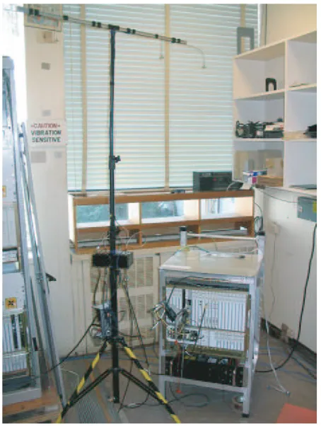
Figure1: Multiantenna base station.
In order to test the MIMO-MUD concept under the harshest conditions, trivial beams are employed: eachw is
identically zero except for the th entry, which is set to 1. With that, the beams give rise to severe interference as no attempt is made to isolate the transmission to different users.
3.2. Transmitter implementation
At the base, omnidirectional vertically polarized 1/ 4-wavelength antennas are set 4 4-wavelengths apart along a line at a height of about 3 m. As shown in Figure 1, the transmitter is mounted on a prototype Lucent base station (OneBTSTM prototype). A prototype mezzanine board is used to implement the physical and MAC (medium access control) layers. The rest of the base station, including RF (ra-dio frequency) front end, backplane, and network interface, is also used. The RF front end, in particular, meets the EVM (error vector magnitude) requirements set by Release 5 of the UMTS specifications.
A FPGA (field-programmable gate array) is used to implement the multiantenna physical layer transmitter. The corresponding functional block scheme is depicted in
Figure 2with each functional block being HSDPA compli-ant. Up to 4 independent data streamsd,∈ {1, 2, 3, 4}, are
passed down from the MAC layer, each intended for a distinct user. After being independently processed, every stream is ra-diated out of one of the antennas with a 24- bit CRC (cyclic redundancy code) word appended to each data block. These data blocks are encoded using a rate-1/3 turbo code and the
desired transmission data rate is realized via a rate match-ing procedure that performs either puncturmatch-ing or repetition of the encoder outputs. Binary words are then mapped to a particular QAM constellation (both QPSK and 16-QAM are supported by HSDPA) and then assigned to specific length-16 orthogonal channelization (i.e., spreading) codes. In ad-dition, a unique pilot drawn from a set of secondary UMTS pilots [8] is assigned to each transmit antenna. The pilots are mutually orthogonal and orthogonal to the data-carrying spreading codes. The pilot power is set to 10% of the total radiated power [13]. The same scrambling code is used at every transmit antenna and the primary and secondary syn-chronization channels are also transmitted allowing mobile terminals to achieve chip-level, slot-level, and frame-level synchronization and to perform cell search procedures. The above functional blocks (in Figure 2) are implemented on FPGA Xilinx Virtex II 6000, with the clock rate of 61.44 MHz using approximately 15% of the available logic (i.e., logic slices), for each user (i.e., transmitted stream). Furthermore, approximately 100 kB memory is used per user.
The rate controller in Figure 2 is closely coupled with the multiuser scheduling that is executed at the MAC layer. Specifically, the rate controller is responsible for setting, for each 2- milliseconds time transmission interval, the rate matching parameters, modulation (QPSK or 16-QAM), and number of active spreading codes . Effectively, it optimizes the transmission data rates for a given channel and data traffic conditions. For the experimental results presented in
Section 4, QPSK modulation was used with rate-1/2 coding and 10 length-16 active spreading codes.
To support multiple users, the MAC layer is implemented on a processor platform. Specifically, the multiuser schedul-ing and hybrid-ARQ are implemented on a digital signal pro-cessor (Texas Instruments DSP 6701), while interfacing to an IP (Internet Protocol) network is implemented on an em-bedded processor (Motorola PowerPC 8260). The standard HSDPA specifications are retained at the MAC layer and thus only the physical layer is aware of the presence of MIMO.
3.3. Receiver implementation
As shown inFigure 3, the terminal antennas are low-profile bow-tie printed dipoles with alternating 45◦ polarizations occupying vertexes of an 8.2 ×5.2 rectangle with the en-tire array fitting on the back of a laptop. Note that the fifth antenna, which is placed in the center of the rectangle (in
Figure 3), is vertically polarized and is used for the uplink transmission (a conventional single transmit antenna up-link is used). Physically different downlink and uplink an-tennas are used to simplify the design by avoiding imple-mentation of an analog antenna coupler (which is otherwise needed when the same antenna is used both for the uplink and downlink, simultaneously).
The functional block scheme of the multiantenna phys-ical layer receiver is illustrated in Figure 4, wheredk is the
d1
d2
d3
d4
Rate controller
CRC generator
Turbo encoder (rate 1/3)
Rate matcher
Physical channel segmenter
. . .
. . . QAM modulator
QAM modulator
Pilot 1 w1
× wL
×
Spreading
summer
Synchronization channels
× + Scrambling
code Transmitter for user 1
Transmitter for user 2
Transmitter for user 3 Transmitter for user 4
Figure2: Functional block scheme of multiantenna HSDPA physical layer transmitter.
Figure3: Terminal and receive antenna array.
After dematching, the turbo decoder ASIC performs iterative decoding. The physical layer is implemented on 3 intercon-nected printed circuit cards that are next described in more detail.
Card 1 implements the analog RF front end outputting up to 4 complex baseband signals, each corresponding to a receive antenna. A heterodyne receiver with a 140 MHz IF and noise figure under 8 dB is utilized, after which 10- bit AD conversion takes place.
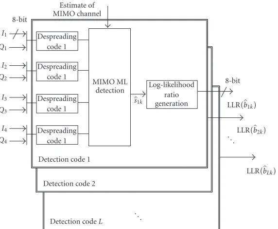
Card 2 contains the basic processing elements of the multiantenna receiver: (i) MIMO-MUD ASIC3[14] and (ii) turbo decoder ASIC [15]. A block scheme of the MIMO de-tector is given inFigure 5. The detector is based on a bank of
3The MIMO-MUD ASIC is manufactured using 0.18-micron CMOS technology, with 438 000 gates, 300 mW core power, and size of 3.7 mm× 3.7 mm.
despreaders matched to the data-carrying spreading codes, whose outputs are fed into the ML detection that corre-sponds with (12). InFigure 5,slk,l ∈ {1,. . .,L}, is the
es-timate of the transmitted symbol corresponding to codelfor userk. Furthermore, each LLR corresponds to 1 channel bit with an 8- bit resolution.
An estimate of the MIMO channel, essential to the detec-tion process, is obtained from an on-chip estimator. This is illustrated inFigure 6, wherehi jdenotes the estimate of the
(i,j)th entry of the MIMO channel matrixHk. The on-chip
estimator is based on a bank of despreaders corresponding to each of the length-512 pilot codes. In the case of frequency-flat fading, the presented estimator results in an ML channel estimate (see [13] and references therein). To lower the esti-mation noise, an optional integrator with forgetting factorα is available. For the experimental results inSection 4,α=0.
Card 3, finally, holds the FPGA that acts as intercon-nect matrix between ADs, MIMO-MUD ASIC, and turbo decoder ASIC. Furthermore, it executes (i) synchronization, (ii) frequency offset compensation, (iii) physical channel de-segmentation, (iv) rate dematching, (v) CRC check, and (vi) numerous auxiliary functions. To all of these functions, the use of MIMO is immaterial. The above functions are imple-mented on FPGA Xilinx Virtex II 6000, with the clock rate of 61.44 MHz using approximately 25% of the available logic and 70 kB of memory.
4. MIMO-MUD EXPERIMENTAL RESULTS
Heterodyne RF Heterodyne
RF Heterodyne
RF Heterodyne
RF AD AD AD AD AD AD AD AD
10-bit
Frequency offset compensation
MIMO MUD ASIC
Synchronization (chip, slot, frame)
Physical channel desegmenter
Rate dematcher
Turbo decoder ASIC (rate 1/3)
CRC check
8-bit 8-bit 8-bit
dk
Figure4: Functional block diagram of multiantenna HSDPA physical layer receiver.
I1 Q1
I2 Q2
I3 Q3
I4 Q4
8-bit
Estimate of MIMO channel Despreading
code 1 Despreading
code 1 Despreading
code 1 Despreading
code 1 Detection code 1
Detection code 2
Detection codeL MIMO ML
detection
s1k
Log-likelihood ratio generation
8-bit LLRb1k
LLRb2k . ..
LLRbLk
. ..
Figure5: MIMO detection as implemented on the MIMO-MUD ASIC.
We measured FERs (frame error rates) with the 2 mil-lisecond time transmission interval specified for HSDPA. Based on the FER and on the 3.84 MHz chip rate, the throughputTis obtained as
T=3.84nT10
16(1−FER)(Mbps). (13)
This corresponds to a system with ARQ where the frames in error are discarded.
Figure 7presents the measured CDF (cumulative distri-bution) of T for a transmit power of 0 dBm (1 mW) over 30 locations. We show, for nT = 4 andK = 4 terminals, each withnR=1, a comparison of SUMF and MIMO-MUD receivers. Also depicted is the throughput for K = 1 and nR=1, for which the SUMF is optimal. Notice the large gains
arising from the use of multiple-antenna transmission. It is also worth noticing the value of multiuser detection alone, which, for example, leads to a throughput increase of more than 0.5 Mbps (at the 50% percentile point) compared to the corresponding single-user optimal transceiver. Figure 8
presents the average throughput for different transmit power levels. MIMO-MUD results, at high transmit powers, in an almost 4-fold increase in average throughput. It should be noted that a higher-order constellation could be used to com-bat the flooring effect shown in the figure for the single-user transceivers. However, multiuser detection would still offer some gains, as evidenced by the fact that it has superior per-formance even before flooring starts to occur (e.g., at 0 dBm transmit power). Figure 9presents the average throughput for nR = 1, 2, 3, 4 with nT = 4 and with 0 dBm (solid line) and 10 dBm (dashed line) transmit powers. Figure 10
I1
Q1
I2
Q2
I3
Q3
I4
Q4 8-bit
Despreading pilot code 1 Despreading pilot code 1 Despreading pilot code 1 Despreading pilot code 1 Estimation pilot 1
Estimation pilot 2 Estimation pilot 3
Estimation pilot 4 ×
×
×
× 1−α
1−α
1−α
1−α +
+
+
+ D
D
D
D ×
×
×
× α
α
α
α h11
h21
h31
h41 h12
h22
h32
h42 h13
h23
h33
h43 h14
h24
h34
h44
Figure6: MIMO channel estimation as implemented on the MIMO-MUD ASIC.
0 0.1 0.2 0.3 0.4 0.5 0.6 0.7 0.8 0.9 1
CDF
0 0.5 1 1.5 2 2.5 3 3.5 4 4.5 5 Throughput (Mbps)
MIMO-MUD,nT=4,nR=1 SUMF,nT=4,nR=1 SUMF,nT=1,nR=1
Figure7: Measured CDF of throughput for 0 dBm over 30 loca-tions.
9and10, we see a sizeable improvement in throughput as-sociated with the use of MIMO-MUD, especially whennTis larger than or comparable to nR. Although, for higher nR, the SUMF approaches the MIMO-MUD throughput, this is in part an artifact of the fact that only QPSK is used. With 16-QAM available, we expect the MIMO-MUD advantage to be largely sustained.
In order to further demonstrate the capabilities of our HSDPA MIMO prototype, we also implemented a video streaming application (using the Real-Time Streaming
0 1 2 3 4 5 6 7 8
Thr
o
ug
hpu
t
(Mbps)
−10 −8 −6 −4 −2 0 2 4 6 8 10 Ptx (dBm)
MIMO-MUD,nT=4,nR=1 SUMF,nT=4,nR=1 SUMF,nT=1,nR=1
Figure8: Measured average throughput versus transmit power over 30 locations.
0 1 2 3 4 5 6 7 8 9 10
Thr
o
ug
hpu
t
(Mbps)
1 2 3 4
Number of receive antennasnR MIMO-MUD,nT=4
SUMF,nT=4
10 dBm 0 dBm
Figure9: Measured average throughput versusnRat 0 dBm (solid line) and 10 dBm (dashed line) over 30 locations.
5. CONCLUSIONS
Multiuser detection is a natural approach to signal detec-tion in multiuser environments. Although much of the de-velopments in this area have been motivated by CDMA, mul-tiuser techniques are equally well suited to the spatial pro-cessing that arises with the use of MIMO, where the role of the CDMA spreading sequences is played by the fading coef-ficients between the various transmit and receive antennas.
In this paper, we have applied MUD to the detection of mutually interfering downlink beam transmissions aimed at different terminals. Without instantaneous channel state in-formation at the base, these beams cannot be rendered or-thogonal at the terminal receivers. Rather than simply endur-ing their mutual interference, we have proposed to jointly de-tect the signals transmitted on the intended and unintended beams.
Besides formulating such MIMO-MUD reception, we have experimentally validated the approach using a testbed that includes a commercial multiantenna base station, mul-tiantenna terminals, and custom MIMO ASICs. The results confirm the power of MUD, especially when the number of receive antennas at each terminal does not exceed the num-ber of transmit antennas at the base.
Besides the application that has constituted the focus of the paper, MIMO-MUD schemes carry over to other multiuser MIMO settings. If, instead of parallel beams, time/frequency multiplexing is utilized, MIMO-MUD can be applied to mitigate the impact of interference from neigh-boring cochannel base stations. Although, in this case, in-dividualizing the channel estimate for each interfering base station may not always be feasible, joint detection of de-sired and undede-sired transmissions can be applied to a few dominant neighbors. Furthermore, simpler linear MMSE processing can be applied if only the aggregate interference
1 1.5 2 2.5 3 3.5 4 4.5 5
Thr
o
ug
hpu
t
(Mbps)
1 2 3 4
Number of receive antennasnR MIMO-MUD,nT=2
SUMF,nT=2
10 dBm 0 dBm
Figure10: Measured average throughput versusnRat 0 dBm (solid line) and 10 dBm (dashed line) over 30 locations.
covariance in (8) can be estimated. Theoretical assessments of the advantage associated with knowledge of such covari-ance in MIMO communication can be found in [17,18,19]. Actually, even before the advent of MIMO systems, earlier pi-oneering contributions had already demonstrated the inter-ference suppression capability of multiple receive antennas [10,20,21].
ACKNOWLEDGMENTS
The authors gratefully acknowledge the support and encour-agement of many colleagues lead by Theodore Sizer, Reinaldo Valenzuela, and Stephen Wilkus, all from Lucent Technolo-gies. The authors are particularly grateful to Peter Bosch, Sape Mullender, Susan Walker, Tran Cuong, Francis Mullany, Eric Beck, Arnold Siegel, Thomas Gvoth, and Ilya Korisch for their support. Part of this work was done under the IST project FITNESS, sponsored and funded by the FP5 Euro-pean Research Framework.
REFERENCES
[1] G. J. Foschini and M. J. Gans, “On the limits of wireless com-munications in a fading environment when using multiple antennas,”Wireless Personal Communications, no. 6, pp. 315– 335, 1998.
[2] I. E. Telatar, “Capacity of multi-antenna Gaussian chan-nels,”European Transactions on Telecommunications, vol. 10, pp. 585–595, 1999.
[3] W. Yu and J. M. Cioffi, “Sum capacity of a Gaussian vector broadcast channel,” inProc. IEEE International Symposium on Information Theory, pp. 498–498, Lausanne, Switzerland, June–July 2002.
[5] P. Viswanath and D. N. C. Tse, “Sum capacity of vector Gaus-sian broadcast channel and uplink-downlink duality,”IEEE Trans. Inform. Theory, vol. 49, no. 8, pp. 1912–1921, 2003. [6] S. Vishwanath, N. Jindal, and A. Goldsmith, “On the capacity
of multiple input multiple output broadcast channel,” inProc. IEEE International Conference on Communications (ICC ’02), vol. 3, pp. 1444–1450, New York, NY, USA, May 2002. [7] K. I. Pedersen, P. E. Mogensen, and J. Ramiro-Moreno,
“Ap-plication and performance of downlink beamforming tech-niques in UMTS,” IEEE Commun. Mag., vol. 41, no. 10, pp. 134–143, 2003.
[8] “Beamforming enhancements,”TR 25.887 v. 1.3.0, 3rd Gener-ation Partnership Project, October 2002.
[9] S. Verd ´u, Multiuser Detection, Cambridge University Press, New York, NY, USA, 1998.
[10] J. H. Winters, “On the capacity of radio communication sys-tems with diversity in a Rayleigh fading environment,”IEEE J. Select. Areas Commun., vol. 5, no. 5, pp. 871–878, 1987. [11] Q. Zhang and S. A. Kassam, “Hybrid ARQ with selective
com-bining for fading channels,”IEEE J. Select. Areas Commun, vol. 17, no. 5, pp. 867–880, 1999.
[12] A. P. Burg, E. C. Beck, D. Samardzija, et al., “Prototype expe-rience for MIMO BLAST over third generation wireless sys-tem,”IEEE J. Select. Areas Commun., vol. 21, no. 3, pp. 440– 451, 2003, Special Issue on MIMO Systems and Applications. [13] D. Samardzija and N. Mandayam, “Pilot assisted estimation of MIMO fading channel response and achievable data rates,” IEEE Trans. Signal Processing, vol. 51, no. 11, pp. 2882–2890, 2003, Special Issue on MIMO.
[14] D. C. Garrett, L. M. Davis, and G. K. Woodward, “19.2 Mbit/s 4×4 BLAST/MIMO detector with soft ML outputs,”IEE Elec-tronics Letters, vol. 39, no. 2, pp. 233–235, 2003.
[15] M. Bickerstaff, L. Davis, C. Thomas, D. Garrett, and C. Nicol, “A 24 Mb/s radix-4 logMAP turbo decoder for 3GPP-HSDPA mobile wireless,” inProc. IEEE International Solid-State Cir-cuits Conference (ISSCC ’03), vol. 1, pp. 150–484, San Fran-cisco, Calif, USA, February 2003.
[16] IST-FITNESS D3.3, “Description of UMTS MTMR reconfig-urability demo,”www.ist-fitness.org.
[17] A. Lozano and A. M. Tulino, “Capacity of multiple-transmit multiple-receive antenna architectures,”IEEE Trans. Inform. Theory, vol. 48, no. 12, pp. 3117–3128, 2002.
[18] A. Lozano, A. M. Tulino, and S. Verd ´u, “Multiple-antenna ca-pacity in the low-power regime,”IEEE Trans. Inform. Theory, vol. 49, no. 10, pp. 2527–2544, 2003.
[19] A. L. Moustakas, S. H. Simon, and A. M. Sengupta, “MIMO capacity through correlated channels in the presence of corre-lated interferers and noise: a (not so) large N analysis,”IEEE Trans. Inform. Theory, vol. 49, no. 10, pp. 2545–2561, 2003. [20] J. H. Winters, J. Salz, and R. D. Gitlin, “The impact of antenna
diversity on the capacity of wireless communication systems,” IEEE Trans. Commun., vol. 42, no. 2/3/4, pp. 1740–1751, 1994. [21] J. H. Winters, “Optimum combining in digital mobile radio with cochannel interference,”IEEE J. Select. Areas Commun., vol. 2, no. 4, pp. 528–539, 1984.
Dragan Samardzija was born in Kikinda, Serbia and Montenegro, in 1972. He re-ceived the B.S. degree in electrical engineer-ing and computer science in 1996 from the University of Novi Sad, Serbia and Mon-tenegro, and the M.S. and Ph.D. degrees in electrical engineering from Wireless In-formation Network Laboratory (WINLAB), Rutgers University, in 2000 and 2004, re-spectively. Since 2000, he has been with
the Wireless Research Laboratory, Bell Labs, Lucent Technologies, where he is involved in research in the field of MIMO wireless sys-tems. His research interests include detection, estimation and in-formation theory for MIMO wireless systems, interference cancel-lation, and multiuser detection for multiple-access systems. He has also been focusing on implementation aspects of various commu-nication architectures and platforms.
Angel Lozanowas born in Manresa, Spain, in 1968. He received the Engineer degree in telecommunications (with honors) from the Polytechnical University of Catalonia, Barcelona, Spain, in 1992, and the M.S. and Ph.D. degrees in electrical engineering from Stanford University, Stanford, California, in 1994 and 1998, respectively. Between 1996 and 1998, he worked for Conexant Sys-tems in San Diego, California. Since January
1999, he has been with Bell Laboratories, Lucent Technologies, in Holmdel, New Jersey. He has authored over 40 papers and 3 book chapters and holds 7 patents. Since October 1999, Dr. Lozano has served as an Associate Editor for IEEE Transactions on Communi-cations.
Constantinos B. Papadias was born in Athens, Greece, in 1969. He received the Diploma of Electrical Engineering from NTUA, Athens, in 1991 and his Doctorate from ENST, Paris, in 1995. From 1992 to 1995, he was a Teaching and Research Assis-tant at Institut Eur´ecom, France. From 1995 to 1997, he was a Postdoctoral Researcher at Stanford University’s Smart Antennas Re-search Group. Since 1997, he has been with