Hardware Manual
(03.2*.**)
For additional resources, visit our Technical Support site on the web at http://ws1.necii.com/ds2000.
5. Maintenance
Options and SMDR
1. Installing the Cabinet
3. Installing Extensions
and Trunks
4. Optional
Equipment
• To use the IntraMail enhancements provided by software versions 03.2*.** and higher, you must use the NEC IntraMail Utility version 1.2 to upgrade your Intra-Mail CompactFlash card. If you don’t upgrade your card, the new features will not be available.
• If upgrading from version 3 software prior to 03.10.08 using telephone program-ming, you must reprogram the options in 1808-IntraMail Subscriber Mailbox Options, 8005-IntraMail Master Mailbox Options, and 8006-IntraMail Rout-ing Mailboxes after the upgrade.
• To avoid having to reprogram the above options, use the latest version of the DS1000/2000 System Administrator to backup and restore the site database. • Go to http://ws1.necii.com/ds2000 to download the latest versions of the Update
Utility, IntraMail Utility, System Administrator, and system software.
2. PCB Installation
This manual has been developed by NEC Unified Solutions, Inc. It is intended for the use of its customers and service personnel, and should be read in its entirety before attempting to install or program the system. Any comments or suggestions for improving this manual would be appreciated. Forward your remarks to:
NEC Unified Solutions, Inc.
4 Forest Parkway Shelton, CT 06484
www.necunifiedsolutions.com
Nothing contained in this manual shall be deemed to be, and this manual does not constitute, a warranty of, or representation with respect to, any of the equipment covered. This manual is subject to change without notice and NEC Unified Solutions, Inc. has no obligation to provide any updates or corrections to this manual. Further, NEC Unified Solutions, Inc. also reserves the right, without prior notice, to make changes in equipment design or components as it deems appropriate. No
representation is made that this manual is complete or accurate in all respects and NEC Unified Solutions, Inc. shall not be liable for any errors or omissions. In no event shall NEC Unified Solutions, Inc. be liable for any incidental or consequential damages in connection with the use of this manual. This document contains proprietary information that is protected by copyright. All rights are reserved. No part of this document may be photocopied or reproduced without prior written consent of NEC Unified Solutions, Inc.
Table of Contents
DS2000 Hardware Manual Table of Contents ◆ i
Table of Contents
Section 1: Installing the Cabinet . . . 1-1
System Preparation and Configuration. . . 1-1
Unpacking. . . 1-1 Before Installing . . . 1-1 Site Requirements. . . 1-1 Expanded Database . . . 1-2 DS2000 Default Numbering . . . 1-2 Automatic Slot Configuration . . . 1-4 System Configuration. . . 1-4 DS2000 Default Configuration . . . 1-4 DS2000 Configuration Guidelines. . . 1-5 DS2000 Load Factor Calculations . . . 1-6Installing the Cabinet . . . 1-8
Planning the Installation . . . 1-8 Removing the Cover. . . 1-9 Unpacking the Wall Mount Bracket. . . 1-10 Mounting the Wall Mount Bracket. . . 1-10 Hanging the Cabinet . . . 1-11Grounding the Cabinet . . . 1-12
Removing the Right Side Panel . . . 1-12 Attaching the Ground Wires. . . 1-12RFI Suppressor Assemblies . . . 1-14
Installing RFI Suppressor Assemblies . . . 1-14Power Supply Installation. . . 1-15
Installing the Power Supply . . . 1-15Table of Contents
ii ◆ Table of Contents DS2000 Hardware Manual
Section 3: Installing Extensions and Trunks . . . 3-1
Connecting Extensions . . . 3-1
Connecting Extensions . . . 3-1Connecting Trunks . . . 3-2
Connecting Analog Trunks. . . 3-2Power Up and System LEDs. . . 3-3
Power-Up . . . 3-3Finishing the Installation . . . 3-5
Reinstalling the Side Panel. . . 3-5 Reinstalling the Front Cover . . . 3-6Section 4: Optional Equipment . . . 4-1
External Paging . . . 4-1
Installing External Paging . . . 4-1 External Paging Relay Control. . . 4-2 Connecting the Relay for External Paging Control . . . 4-2 Programming the Relay for External Paging Control . . . 4-3 Additional Programming . . . 4-3Music Source. . . 4-4
Installing a Music Source . . . 4-4 Programming Background Music. . . 4-4 Programming Music on Hold . . . 4-4Power Failure Telephone . . . 4-5
Power Failure Cut-Through . . . 4-5DSS Console . . . 4-6
Installing a DSS Console . . . 4-6 Programming DSS Consoles . . . 4-62-OPX Module. . . 4-8
Installing the 2-OPX Module . . . 4-8 Programming 2-OPX Modules. . . 4-9 Wall Mounting the 2-OPX Module . . . 4-10Wall-Mount Kit . . . 4-11
Installing the Wall-Mount Kit . . . 4-11 Wall-Mounting a Key Telephone. . . 4-11Desk Stand . . . 4-13
Using the Desk Stand . . . 4-13REJ Recording Jack . . . 4-14
Installing the REJ Recording Jack . . . 4-14Keyset Self Test . . . 4-16
Testing the Keyset . . . 4-16Table of Contents
DS2000 Hardware Manual Table of Contents ◆ iii
PC Card Backup Error Messages . . . 5-2
Restoring Site Data. . . 5-4
Restoring Site Data from a PC Card. . . 5-4 PC Card Restore Error Messages . . . 5-4Loading New System Software . . . 5-5
Loading System Software from a PC Card . . . 5-5SMDR. . . 5-6
Installing SMDR. . . 5-6 Programming SMDR . . . 5-6 Testing the Connection. . . 5-7 Checking the System’s Serial Port Settings . . . 5-7Modem Installation. . . 5-8
Installing a Modem. . . 5-8Making Your Own Data Cables . . . 5-9
System Reset . . . 5-10
Resetting Your System . . . 5-10Section 6: Specifications and Parts . . . 6-1
Specifications . . . 6-1
Parts List . . . 6-6
Table of Contents
System Preparation and Configuration
DS2000 Hardware Manual Section 1: Installing the Cabinet ◆ 1-1
1
Section 1: Installing
the Cabinet
System Preparation and ConfigurationSystem Preparation and Con
fi
guration
Unpacking
Unpack the equipment and check it against your equipment lists. Inspect for physical damage. If you are not sure about a component’s function, review the Product Description Manual. Contact your Sales Representa-tive if you have additional questions.
Have the appropriate tools for the job on hand, including: a test set, a punch down tool and a digital voltmeter.
Before Installing
Make sure you have a building plan showing the location of the common equipment, extensions, the telco demarcation and earth ground. In addition, the installation site must meet the requirements outlined in the Standard Practices Manual.
Site Requirements
System Preparation and Configuration
1-2 ◆ Section 1: Installing the Cabinet DS2000 Hardware Manual
Expanded Database
The Expanded Database is a new database method that provides database records (memory) for all possible extensions, trunks, Hunt Groups, Ring Groups, and Voice Mail ports. This new capability allows for:
● Automatic Slot Configuration.
● Simplified installation of Voice Mail, Hunt Groups, and Ring Groups.
● Support for built-in UltraMail and IntraMail Voice Mail
● Introduction of the DS-Series PC Program.
To understand the Expanded Database, you’ll need to keep track of three things: port, station (or trunk) number, and extension number.
● Port
The port is where the device you are programming connects to the system. For example, each 16DSTU PCB has 16 ports which can connect up to 16 digital telephones. Ports are numbered consecutively for each slot, and only exist when you plug in the PCB to which the device should connect.
● Station Number and Trunk Number
The station or trunk number is the element in software that keeps track of the connected devices’s programming. Station and trunk numbers (and associated database records) exist for all possible devices you can connect to the system, even if you don’t have any ports installed to connect them. You can’t call station and trunk numbers directly - you need the associated extension numbers to do that (see below).
● Extension Numbers
Extension numbers allow you to access the stations and trunks. By default, each station and trunk number has an extension number assigned to it. You can change these assignments if you want to.
- Digital station ports have primary and secondary station numbers. The primary station’s extension number is used to call the device connected to the port. The secondary station’s extension number calls the second channel on 2-channel devices such as 2-OPX Modules and Digital VANGARD Voice Mail ports.
DS2000 Default Numbering
Here is how the ports, station numbers, trunk numbers, and extension numbers are initially set up.
Default Numbering in DS2000
Stations (Telephones) Ports Station Numbers Extension Numbers
Station Set by installed PCB 1-96 300-395
Unassigned1 32 97-128 396-427
Total Station Ports 128 -
-• To find out the default extension number for any station number, add 299 to the station number. - For example, station number 1 uses extension number 300 (1 + 299).
Trunks Ports Trunk Numbers Extension Numbers
Trunk Ports Set by installed PCB 1-64 101-164
Total Trunk Ports 64 -
System Preparation and Configuration
DS2000 Hardware Manual Section 1: Installing the Cabinet ◆ 1-3
1
The following table shows the port capacity of each DS2000 PCB.
Since the Expanded Database maintains database records for all extensions and trunks, you have the option of using Program 9902 - Set Up Stations (DS2000)and Program 9903 - Set Up Trunks (DS2000) to assign a station and a trunk PCB to the same slot. When you plug in an ASTU or DSTU PCB into the slot, the ports on the PCB access the associated station numbers. If you remove that PCB and plug an ATRU in its place, the ports on the ATRU PCB access the associated trunk numbers. Refer to the Software Manual on the System Document CD that came with your sys-tem for more.
Voice Mail Stations Station Numbers Extension Numbers
201-208 500-507
UCD Groups Total Groups UCD Group Master Extension Numbers
8 700-707
Ring Groups Total Groups Ring Group Master Extension Numbers
8 600-607
1 Available for digital station port secondary station numbers. These are used for the second channels on 2-OPX
Modules and Digital VANGARD Voice Mail.
DS2000 PCB Port Capacities
PCB Description Port Capacity
Station PCBs
16DSTU PCB 16 Digital Station PCB 16 (1-16)
4ASTU PCB 4 Analog Station PCB 4 (1-4)
8ASTU PCB 8 Analog Station PCB 8 (1-8)
Trunk PCBs
4ATRU PCB 4 Analog Trunk PCB 4 (1-4)
8ATRU PCB 8 Analog Trunk PCB 8 (1-8)
T1 PCB T1/E1 PCB 24 (1-24) when enabled for T1 30 (1-30) when enabled for E1
System Preparation and Configuration
1-4 ◆ Section 1: Installing the Cabinet DS2000 Hardware Manual
Automatic Slot Configuration
Automatic Slot Configuration automatically sets up station and trunk PCBs when you initially power up the system. This simplifies installation because you no longer have to use system pro-gramming to activate station and trunk PCBs after you plug them in.
Here’s how Automatic Slot Configuration works:
● With power off, install your station and trunk PCBs.
With the system powered down, install the station and trunk PCBs from left to right in the order you want your extension and trunk numbers set up.
- Be sure to install a 16DSTU (16 Digital Station) PCB in the first slot (CN1).
- You don’t have to group your station and trunk PCBs together, although it may be more convenient to do so. For example, when setting up a 16x32 system, you can install the 2nd DSTU PCB and your two ATRU PCBs in any slot, in any order. Automatic Slot Confi gura-tion will properly handle the numbering.
● Power up the system.
On power up, the system scans the PCBs from left to right and sets up the extension and trunk numbering as follows.
- Extension numbers will begin with 300 in the first slot and increment from left to right. - Trunk numbers will begin with 101 (starting from the first installed ATRU PCB) and will
also increment from left to right.
- For example, in a 16x32, the numbering will be: 1st 16DSTU PCB = Extensions 300-315. 2nd 16DSTU PCB = Extensions 316-331. 1st 8ATRU PCB = Trunks 101-108. 2nd 8ATRU PCB = Trunks 109-116.
System Configuration
DS2000 Default Configuration
Automatic Slot Configuration automatically sets up your system’s PCBs when you initially power up the sys-tem. There is no longer a factory-installed default configuration, and you don’t have to use system programming to activate PCBs after you plug them in. Remember, you should always plug a 16DSTU PCB into slot CN1.
System Preparation and Configuration
DS2000 Hardware Manual Section 1: Installing the Cabinet ◆ 1-5
1
DS2000 Configuration Guidelines
The total number of components you can install and connect depends on power supply capacity and the Sys-tem Load Factor. Review the DS2000 Configuration Guidelines table below and DS2000 Load Factor Cal-culations on page 1-6 when configuring your system.
DS2000 Configuration Guidelines
4 Slot Cabinets
• Do not install more than 2 16DSTU PCBs under any circumstances. • The first 16DDSTU PCB you install must be in the first slot (CN1). • Maximum configuration is 112 ports.
• The total of all extensions and trunks cannot exceed 112.
• Always use the System Load Factor table to check your system configuration.
8 Slot Cabinets
• Do not install more than 2 16DSTU PCBs for each power supply. (Install your power supplies in the following order: slot CN101, slot CN103, slot CN102.)
• The first 16DSTU PCB you install must be in the first slot (CN1). • The total of all extensions and trunks installed cannot exceed 112. • Maximum configuration is 112 ports.
System Preparation and Configuration
1-6 ◆ Section 1: Installing the Cabinet DS2000 Hardware Manual
DS2000 Load Factor Calculations
The combination of trunks, extensions, 2-OPX Modules and DSS Consoles you can connect to your DS2000 system may be limited by the System Load Factor. Use the DS2000 System Load Factor Calculations chart on the next page to verify your system’s configuration. When entering data on the chart, for each installed item make entries for each Load Type. There are two Load Types to consider: 5 VDC and 40 VDC.
To check your system configuration:
1. Indicate the quantity for each PCB, DSS Console, and 2-OPX Module installed in the Qty column.
The number of keysets and single line sets does not affect the System Load Factor.
2. For each item for each Load Type, multiply the Qty times the Load and enter the value in the Total
column.
For example, two 16DSTU PCBs have a load of 6 for 5 VDC and 40 for 40 VDC.
3. Add up the entries in each Total column and enter the values in Item 1: Load Type Totals.
4. Review Item 2: Power Supply Capacity and determine the capacity of the power supplies installed in your system.
5. Compare the capacities in Item2 to your entries in Item1. Item1 must always be equal to or less than the entry in Item2.
!! Important !!
System Preparation and Configuration
DS2000 Hardware Manual Section 1: Installing the Cabinet ◆ 1-7
1
DS2000 System Load Factor CalculationsDescription Qty
Load Type
5 VDC 40 VDC
Load Total Load Total
CPU PCB 1 6 6 0 0
16DSTU PCB 3 20
4ASTU PCB 3 5
8ASTU PCB 5 8
16ASTU PCB 10 17
4ATRU PCB 4 0
8ATRU PCB 8 0
T1 PCB 8 0
UltraMail PCB (FMS) 19 0
UltraMail 2000 PCB (VMS) 0 6
Telephones (Keysets and SLTs) 0 0
110-Button DSS Console 0 2
24-Button DSS Console 0 1
2-OPX Module 0 3
Item 1: Load Type Totals
(Cannot exceed Item 2: Power Supply Capacity.)
Item 2: Power Supply Capacity
If you have one power supply installed, the capacity is: If you have two power supplies installed, the capacity is: If you have three power supplies installed, the capacity is:
5 VDC = 40 5 VDC = 80 5 VDC = 120
40 VDC = 48 40 VDC = 80 40 VDC = 120
Notes:
• A 4 slot cabinet can only have 1 power supply.
• An 8 slot cabinet can have up to 3 power supplies. You cannot have more than two 16DSTU PCBs per power sup-ply, regardless of System Load Factor calculations.
• Exceeding the allowed Load Type Total (Item 1) will cause the system’s power supplies to automatically shut down and/or cause erratic system operation.
• Total DSS Consoles installed cannot exceed 4.
Installing the Cabinet
1-8 ◆ Section 1: Installing the Cabinet DS2000 Hardware Manual
Installing the Cabinet
Planning the Installation
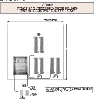
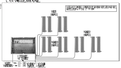
Before installing the common equipment, you should mount a Main Distribution Frame (MDF) plywood back-board in a centrally located spot. A 1/2 sheet of plywood (4’ x 4’) should be adequate for a 4 slot cabinet (see Figure 1-1 4 Slot Cabinet Installation Layout below). A full sheet of plywood (8’ x 4’) should be adequate for an 8 slot cabinet (see Figure 1-2 8 Slot Cabinet Installation Layout on page 1-9). Be sure to mount the back-board using suitable fasteners, taking care to adhere to standard installation practices and local codes.
The equipment cabinet requires a three-prong, dedicated 110 VAC 60 Hz circuit (NEMA 5-15 receptacle). The AC receptacle must be within 7 feet of the cabinet’s lower left corner.
Normally, you install the extension and trunk blocks to the right of the cabinet. Telco should also install the RJ21X to the right of the cabinet.
!! Important !!
Local codes may prohibit you from installing extensions, trunks and optional equipment in the same blocks.
Figure 1-1: 4 Slot Cabinet Installation Layout
80000 - 15A
Plywood backboard
Dedicated AC Outlet Surge
Protector
To earth ground To telco
ground
Station Blocks
Station Blocks Trunk
Blocks 4'
4'
Installing the Cabinet
DS2000 Hardware Manual Section 1: Installing the Cabinet ◆ 1-9
1
Removing the Cover
Before wall-mounting, remove the cover on the Main Equipment Cabinet.
To remove the cover (Figure 1-3):
1. Unscrew the two captive screws on the front of the cabinet cover.
2. Lift up slightly on the front of the cover — then gently slide the cover back to remove it.
Figure 1-2: 8 Slot Cabinet Installation Layout
Figure 1-3: Removing the Cover
80000 - 61
8' X 4' Plywood backboard
Surge
Protector To telcoground To earthground
Station Blocks Trunk
Blocks
Station Blocks
Dedicated AC Outlet
Note: The system will respond to telco ring signal in the range of 40-130 VAC @ 20 Hz.
80000 - 12
Installing the Cabinet
1-10 ◆ Section 1: Installing the Cabinet DS2000 Hardware Manual
Unpacking the Wall Mount Bracket
The wall mount bracket and screws (see Figure 1-4 Wall Mount Bracket below) are taped to the packing material in the Main Equipment Cabinet box. Unpack the wall mount bracket and mounting screws.
Mounting the Wall Mount Bracket
Mount the wall mount bracket (see Figure 1-5 Mounting the Wall Mount Bracket below) on the MDF in a convenient location, about 12” higher than where you want the bottom of the cabinet to line up.
Figure 1-4: Wall Mount Bracket
Figure 1-5: Mounting the Wall Mount Bracket
80000 - 1 1
Installing the Cabinet
DS2000 Hardware Manual Section 1: Installing the Cabinet ◆ 1-11
1
Hanging the Cabinet
To hang the cabinet:
1. Hang the Main Equipment Cabinet on the wall mount hanger as shown:
- See Figure 1-6 Hanging the 4 Slot Cabinet below when hanging a 4 slot cabinet. - See Figure 1-7 Hanging the 8 Slot Cabinet below when hanging an 8 slot cabinet.
2. Using the remaining screws packed with the hanger, secure the cabinet to the plywood backboard.
Figure 1-6: Hanging the 4 Slot Cabinet
Figure 1-7: Hanging the 8 Slot Cabinet
80000 - 13
Grounding the Cabinet
1-12 ◆ Section 1: Installing the Cabinet DS2000 Hardware Manual
Grounding the Cabinet
Removing the Right Side Panel
Remove the cabinet right side panel to gain easy access to the ground lugs and system cabling. The cabinet has two ground connections: ETH (Earth Ground) and PBXG (PBX Ground).
To remove the right side panel (Figure 1-8):
1. Remove the two screws that secure the right side panel to the cabinet. 2. Carefully slide the right side panel down until it swings clear of the cabinet.
Attaching the Ground Wires
The system provides two ground terminations. Each ground connects from the system to the ground termina-tion using 12 AWG stranded copper wire.
● Use the ETH (Earth Ground) for safety/system ground. You must connect ETH to a known earth ground.
● Use the PBXG (PBX Ground) if you have trunks that require telco ground (such as ground start trunks). This ground is not required for loop start trunks.
Figure 1-8: Removing the Right Side Panel
!! Important !!
You must connect your system to a known earth ground according to the following instructions.
80000 - 16
Grounding the Cabinet
DS2000 Hardware Manual Section 1: Installing the Cabinet ◆ 1-13
1
To attach the ground wires (Figure 1-9):1. Remove the lug on the ground connection you want to connect.
2. Follow Figure 1-10 Installing RFI Suppressor Assemblies on page 1-14 and run the ground wire(s) through the RFI Suppressor Assembly as shown.
3. Crimp ring terminals as required to the ground wires. 4. For earth ground:
Run a ground wire from the ETH lug to a known earth ground.
For PBX Ground:
Run a ground wire from the PBXG lug to the telco ground.
If your system will have a T1 Trunk PCB:
Run a 12 AWG jumper wire from the SG (Signal Ground) lug to the ETH (Earth Ground) lug. 5. Reinstall and firmly tighten the lug(s) removed in step 1 above.
!! Important !!
Do not plug in the power cord or reinstall the right side panel until all PCB installation and cabling are complete.
Figure 1-9: Attaching the Ground Wires
80000 - 17-1
To earth ground For T1 Trunk
PCB only
To telco ground Proper grounding is required.
RFI Suppressor Assemblies
1-14 ◆ Section 1: Installing the Cabinet DS2000 Hardware Manual
RFI Suppressor Assemblies
Installing RFI Suppressor Assemblies
You must install RFI Suppressor Assemblies as follows (see Figure 1-10 Installing RFI Suppressor Assemblies
below). The suppressors must be mounted inside the cabinet and as close to the appropriate PCB as possible.
● For Ground Wires
– You must install a separate RFI assembly for the ground wire(s) in all systems. – If your system has 2 ground wires, install them both in the same assembly.
● For CPU Connections
– You must install a separate RFI assembly for the CPU mod jack and RS-232 cables in all systems. – Install both cables in the same assembly.
Figure 1-10: Installing RFI Suppressor Assemblies For Ground Wires
• Required for all installations.
For CPU Connections
Power Supply Installation
DS2000 Hardware Manual Section 1: Installing the Cabinet ◆ 1-15
1
Power Supply Installation
Installing the Power Supply
The power supply provides the DC power sources required to operate the system.
To install a power supply (Figure 1-11) (Figure 1-12):
1. Slide the power supply into the CN101 slot. See Figure 1-12 Installing the Power Supply below. 2. Using a long-shaft phillips head screwdriver, tighten the two screws that secure the power supply.
An 8 slot cabinet may require up to 3 power supplies, using slots CN101, CN102 and CN103. Refer to
System Configuration on page 1-4 for more. Install the first supply in slot CN101. Install the second supply in slot CN103. Install the third supply in slot CN102.
Figure 1-11: Power Supply
Figure 1-12: Installing the Power Supply Important Compatibility Guidelines
• Only install Power Supply P/Ns 80005B or 80005C. • Do not install Power Supply P/Ns 80005 or 80005A. • You can mix P/Ns 80005B and 80005C in the same system. • If your system uses UltraMail or UltraMail 2000, you must
install only Power Supply P/Ns 80005C.
80000 - 29
Power Supply Installation
PCB Location
DS2000 Hardware Manual Section 2: PCB Installation ◆ 2-1
2
Section 2: PCB
Installation
PCB LocationPCB Location
Where to Install the PCBs
Review System Configuration on page 1-4 before installing any PCBs. Always observe the System Load Factor when configuring your system.
● The CPU (Central Processing Unit) PCB must plug into slot CN0.
● A 16DSTU (16 Digital Station) PCB must plug into slot CN1.
● All other PCBs (including 16DSTU PCBs) can plug into slots CN2-CN8. - Slots CN5-CN8 are only available with the 8 slot cabinet.
- A 4 slot cabinet can only accept two 16DSTU PCBs.
- In an 8 slot cabinet, you can have only two 16DSTU PCBs per power supply.
!! Important !!
Install telephones connected to DSTU and ASTU PCBs as on-premise extensions only.
!! Caution !!
• Do not plug in the CPU PCB hot (i.e., with the system power applied). • You can plug in ASTU and ATRU PCBs hot as required.
Installing PCBs
2-2 ◆ Section 2: PCB Installation DS2000 Hardware Manual
Installing PCBs
Central Processing Unit (CPU) PCB
The CPU PCB (Figure 2-1) provides:
● The system’s central processing, stored program and memory for the customer’s site-specific data.
● PC Interface Card.
● Conference circuits, DTMF receivers and DTMF generators.
● External music input and on-board synthesized music source.
● External paging output and associated relay.
● Real Time Clock.
● Battery for short term (14 day) backup of the customer’s site-specific data.
Installing the CPU
The CPU PCB installs in the CN0 slot in the Main Equipment Cabinet.
To install the CPU PCB (Figure 2-2) (Figure 2-3):
1. Slide the Mode Switch to the RUN position.
2. Insert the battery (Sony CR2032 or NEC P/N EX0254-0040) into the battery clips. 3. Plug the CPU into slot CN0.
Figure 2-1: CPU PCB
Figure 2-2: Setting Up the CPU
80000 - 26
Refer to Section 4, Optional Equipment for instructions on connecting the music source, External Paging, and the auxil-iary relay.
Mode Switch
Installing PCBs
DS2000 Hardware Manual Section 2: PCB Installation ◆ 2-3
2
Digital Station (16DSTU) PCB
The 16DSTU provides the connection for 16 digital telephones. Refer to Section 3, Installing Extensions and Trunks for wiring instructions.
To install the 16DSTU PCB (Figure 2-4) (Figure 2-5):
1. Plug the 16DSTU PCB for extensions 300-315 into slot CN1.
2. Plug in additional 16DSTU PCBs as required. See System Configuration on page 1-4 for more. 3. Set the mode switch on each installed 16DSTU PCB to RUN.
Figure 2-3: Installing the CPU
!! Important !!
• In a 4 slot cabinet, you cannot install more than 2 16DSTU PCBs.
• In an 8 slot cabinet, you cannot install more than 2 16DSTU PCBs per power supply. 80000 - 30
Installing PCBs
2-4 ◆ Section 2: PCB Installation DS2000 Hardware Manual
Figure 2-4: Digital Station (16DSTU) PCB
Figure 2-5: Installing the 16DSTU PCB
Mode switch
80000 - 31
Installing PCBs
DS2000 Hardware Manual Section 2: PCB Installation ◆ 2-5
2
Analog Station (8ASTU and 4ASTU) PCBs
The 8ASTU PCB provides connection for 8 analog extensions. The 4ASTU PCB connects 4 analog extensions. Refer to Section 3, Installing Extensions and Trunks for wiring instructions.
To install the ASTU PCB (Figure 2-6) (Figure 2-7):
1. Plug in ASTU PCBs as required. See System Configuration on page 1-4 for more. 2. Set the mode switch on each ASTU PCB to RUN.
Figure 2-6: Analog Station (ASTU) PCB
Figure 2-7: Installing the ASTU PCB
Mode switch
80000 - 31A
Installing PCBs
2-6 ◆ Section 2: PCB Installation DS2000 Hardware Manual
16-Port Analog Station (16ASTU) PCB
The 16ASTU PCB provides connection for 16 analog extensions.
To install the 16ASTU PCB (Figure 2-8) (Figure 2-9):
1. Check your system configuration to be sure you do not exceed the allowable System Load Factor. 2. Plug the 16ASTU PCB into any available slot from CN2-CN8.
You should reserve CN1for a 16DSTU PCB. The PCB will auto-ID when you plug it in.
3. Set the mode switch on the 16ASTU PCB to RUN.
Figure 2-8: 16-Port Analog Station (16ASTU) PCB
Figure 2-9: Installing the 16ASTU PCB
Mode switch
Installing PCBs
DS2000 Hardware Manual Section 2: PCB Installation ◆ 2-7
2
Analog Trunk (8ATRU and 4ATRU) PCBs
The 8ATRU provides connection for 8 loop start analog trunks. The 4ATRU PCB connects 4 loop start analog trunks. Refer to Section 3, Installing Extensions and Trunks for wiring instructions.
To install the ATRU PCB (Figure 2-10) (Figure 2-11):
1. Plug in ATRU PCBs as required. See System Configuration on page 1-4 for more. 2. Set the mode switch on each ATRU PCB to RUN.
Figure 2-10: Analog Trunk (ATRU) PCB
Figure 2-11: Installing the ATRU PCB
Mode switch
Notes:
• The system will respond to telco ring signal in the range of 42-103 VAC @ 20 Hz.
• Telco battery must be 44-56 VDC.
80000 - 32
Installing PCBs
2-8 ◆ Section 2: PCB Installation DS2000 Hardware Manual
T1 Trunk PCB
The T1 Trunk PCB (Figure 2-12) provides advanced digital trunking and gives the DS2000 a maximum of 24 trunks in a single PCB slot. The available T1 trunk types include:
● Loop Start and Ground Start (DTMF and Dial Pulse)
● Direct Inward Dialing (DID) Wink Start and Immediate Start (DTMF and Dial Pulse)
● E&M Tie Line Wink Start and Immediate Start (DTMF and Dial Pulse)
Notes
● Although the T1 PCB can connect directly to the telco’s T1 smart jack, a separately-purchased Channel Service Unit (CSU) between the smart jack and the T1 PCB is recommended. Additionally, your telco may require a CSU.
● Normally, the T1 PCB connects to the telco’s T1 smart jack or your CSU using a standard straight-through CAT 5 cable. However, always check the documentation that came with your CSU for cabling requirements.
● The T1 PCB installs in any universal slot but slot 1.
● A commercially available T1 Tester is recommended.
To install the T1 Trunk PCB (Figure 2-13) (Figure 2-14):
1. Set jumpers CN7 and CN9 to the T1 position.
The DS2000 T1 PCB requires system software version 03.03.00 or higher and expanded memory CPU P/N 80025B.
Installing PCBs
DS2000 Hardware Manual Section 2: PCB Installation ◆ 2-9
2
2. Plug in T1 Trunk PCBs as required. See System Configuration on page 1-4 for more. 3. Set the mode switch on each T1 PCB to RUN.
4. Using a standard straight-through CAT 5 cable, connect the T1 PCB RJ48C connector to the Telco Smart Jack or your Channel Service Unit.
Although the T1 PCB can connect directly to the telco’s T1 smart jack, a separately purchased Channel Service Unit (CSU) between the smart jack and the T1 PCB is recommended. Additionally, your telco may require a CSU.
Figure 2-13: T1 Trunk PCB Setup
E1
T1
CN9
E1
T1
CN7
CN9
CN7
80061 - 2
1 2 3 4 5 6 7 8
RX1 T RX1 R
TX1 T TX1 R
RJ48C Connector Pinouts
RJ48C Connector Mode switch
RS232 Port
Straight-Through CAT 5 Cable
Telco Smart Jack
Installing PCBs
2-10 ◆ Section 2: PCB Installation DS2000 Hardware Manual
Figure 2-14: Installing the T1 Trunk PCB
4 Slot Cabinet Shown
Installing PCBs
DS2000 Hardware Manual Section 2: PCB Installation ◆ 2-11
2
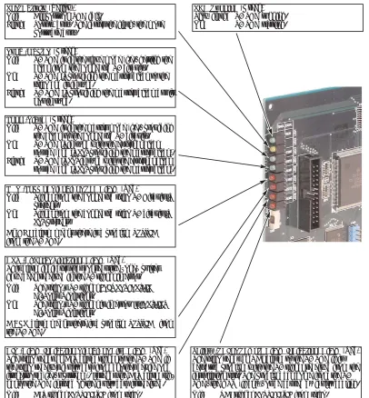
T1 PCB Leds
Figure 2-15: T1 PCB LEDs PCB Running(Green) Slow flash: T1 PCB running. On: T1 PCB starting.
Port Activity(Yellow) Off: All ports on PCB idle.
Flash: Port(s) busy. The faster the flash, the more ports are busy.
Sync (Master)(Green)
Off: T1 PCB is in the slave mode (i.e., getting the clock from the connected T1 circuit). On: T1 PCB isproviding the master clock to the
telco and is in sync.
Flash: T1 PCB isproviding the master clock but is not in sync.
Loop (Slave)(Green)
Off: T1 PCB is in the master mode (i.e., providing the clock to the connected T1 circuit). On: T1 PCB isin sync with the external clock
source (and is notproviding the master clock). Flash: T1 PCBis notin sync with the external clock
source (and is notproviding the master clock).
LOS (Loss of Signal) or Red Alarm(Red)
Off: Signal from the connected telco T1 Circuit is
present.
On: Signal from the connected telco T1 circuit is notpresent.
An LOSalarm means there is a problem upstream
from the T1 PCB.
BPV (Bi-Polar Violation) Alarm(Red)
This alarm indicates that consecutive “one” pulses have been received in the T1 signal in error. Off: The telco’s T1 signal does not contain
Bi-Polar Violations.
On: The telco’s T1 signal is in error. It contains
Bi-Polar Violations.
ABPValarm means there is a problem upstreamfrom the T1 PCB.
AIS (Alarm Indication Signal) or Blue Alarm(Red) The telco sends an AIS alarm signal to the T1 PCB if the telco receives faulty data from another device on its network (i.e., upstream). It sends the AIS alarm sig-nal to the PCB instead of the faulty data it received. Off: AIS signal not receivedfrom telco. On: AIS receivedfrom telco.
An AISalarm means there is a problem upstream
from the telco (and upstream from the T1 PCB).
Yellow (RAI or Remote Alarm Indication) Alarm(Red) The telco sends an RAI alarm to the T1 PCB if it detects a problem with the T1 signal received from the installation site. The problem can come from the T1 PCB, the CSU (if any), or be caused by faulty cabling. Off: RAI signal not receivedfrom telco.
On: RAI receivedfrom telco.
An RAIalarm means there is a problem downstream
from the telco (i.e., in the T1 PCB, CSU, or cabling).
T1 PCB CSU
Telco
Upstreamfrom T1 PCB
Installing PCBs
2-12 ◆ Section 2: PCB Installation DS2000 Hardware Manual
T1 Programming Summary
For more in depth feature description and programming details, refer to the following features in the
DS1000/2000 Software Manual (P/N 80000SWG**): Direct Inward Dialing, T1 Trunking, and Tie Lines.
Basic Programming
● 1001 - Trunk Circuit Type
Set the circuit type for each T1 trunk. The available types are: - 51 (Loop Start DTMF)
- 52 (Loop Start DP) - 53 (Ground Start DTMF) - 54 (Ground Start DP) - 57 (DID DTMF Wink Start) - 58 (DID DP Wink Start)
- 59 (DID DTMF Immediate Start) - 60 (DID DP Immediate Start) - 61 (E&M DTMF Wink Start) - 62 (E&M DP Wink Start)
- 63 (E&M DTMF Immediate Start) - 64 (E&M DP Immediate Start)
● 9904 - T1/E1 Configuration
Use this option to set parameters for the T1 PCB.
● Clock Control
Default: T1 PCB is the clock master.
● If a T1 PCB is connected to a telco T1 circuit, it is usually set as clock slave (i.e., uses the telco clock source).
● If a T1 PCB is connected to a private T1 circuit, set the clock source according to the net-work configuration.
- Transmit Pulse Amplitude
Default: 0 (0dB), the T1 PCB is within 133’ of smart jack or CSU. - Framer Type
Default: ESF - Extended Super Frame. - Zero Suppression
Default: Enabled - B8ZS. - Number of PCM Channels
Default: 0 - All channels active. The active channels are always the lower-numbered circuits (i.e., an entry of 8 means that channels 1-8 are active).
- Loopback
Default: 0 - No loopback options enabled.
ANI/DNIS Programming
● 1001 - Caller ID
Enter 3 to enable ANI-based Caller ID.
● 1001 - ANI/DNIS
Specify the type of ANI/DNIS Caller ID provided by your T1 trunks. The options are: - 0 (None)
- 1 (ANI) - 2 (*ANI*) - 3 (*DNIS*) - 4 (*ANI*DNIS)
● l001 - ANI Delimiter
For ANI/DNIS options 2-4 above, specify the ANI delimiter (0-9, # or *).
● 1001 - Number of ANI Digits
Installing PCBs
DS2000 Hardware Manual Section 2: PCB Installation ◆ 2-13
2
DID Programming (Basic)● 1401 - Number of DID Digits
Specify the number of DID Digits (1-8) expected from the telco.
● 1402 - DID Translation Table
Set up the system’s DID routing.
Refer to your Software Manual for additional options for setting up DID Camp On and DID Overflow.
Tie Line Programming (Basic)
Refer to your Software Manual for additional options for setting up Tie Line trunk and operator access.
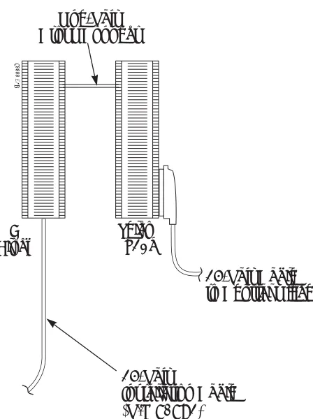
If you don’t have a T1 Tester, you can alternately test Tie Line operation between two T1 PCBs in the same cabinet or facility using the cable shown below (Figure 2-16).
Figure 2-16: Connecting Two T1 PCBs Together without a Telco T1 Circuit (For Tie Line Testing)
Pin
Latch faces up
To T1 PCB To T1 PCB
80061 - 3
1 2 3 4 5 6 7 8
RX1T RX1R TX1T
TX1R TX1RTX1T RX1R RX1T
Connecting Blocks
2-14 ◆ Section 2: PCB Installation DS2000 Hardware Manual
Connecting Blocks
Working With 8-Pin Jacks
The system uses 8-pin mod jacks to connect extensions, trunks and optional equipment. Using the Installation Cable (P/N 80892) makes it easy to connect the PCBs to standard 66M1-50 connecting blocks. These cables have six 8-pin modular jacks on one end and are unterminated on the other. In general, each cabinet needs:
● One 66M1-50 block and Installation Cable (P/N 80892) for extensions and optional equipment.
● One 66M1-50 block and Installation Cable (P/N 80892) for trunks.
● Depending on your PCB configuration and local codes, you may need an additional 66M1-50 block and Installation Cable (P/N 80892) for optional equipment.
Punching Down the Cables
The Installation Cables have six 8-pin jacks installed on one end and are unterminated on the other. Each 8-pin jack connects 4 extensions or 4 trunks.
To punch down the cables (Figure 2-17)through (Figure 2-21):
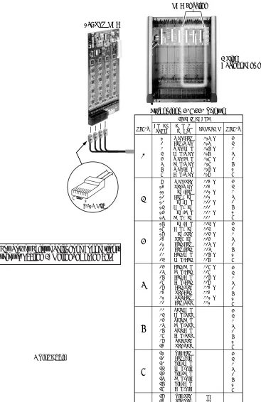
1. For each 66M1-50 block, punch down the Installation Cable in standard color-code order.
- Use Figure 2-17 Connecting 16DSTU Digital Station and 4/8ASTU Analog Station PCBs on page 2-15 when connecting extensions.
- Use Figure 2-19 Connecting 4/8ATRU Trunk PCBs on page 2-17 when connecting trunks.
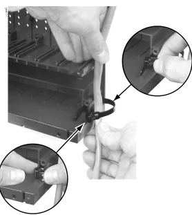
2. After you have punched down your cables, route them through the side of the cabinet and secure them with the strain relief (Figure 2-20 Securing the Cables on page 2-18).
Making Your Own Cables
Connecting Blocks
DS2000 Hardware Manual Section 2: PCB Installation ◆ 2-15
2
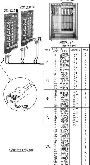
Figure 2-17: Connecting 16DSTU Digital Station and 4/8ASTU Analog Station PCBs
WHT-BLU BLU-WHT WHT-ORN ORN-WHT WHT-GRN GRN-WHT WHT-BRN BRN-WHT WHT-SLT SLT-WHT RED-BLU BLU-RED RED-ORN ORN-RED RED-GRN GRN-RED RED-BRN BRN-RED RED-SLT SLT-RED BLK-BLU BLU-BLK BLK-ORN ORN-BLK BLK-GRN GRN-BLK BLK-BRN BRN-BLK BLK-SLT SLT-BLK YEL-BLU BLU-YEL YEL-ORN ORN-YEL YEL-GRN GRN-YEL YEL-BRN BRN-YEL YEL-SLT SLT-YEL VIO-BLU BLU-VIO VIO-ORN ORN-VIO VIO-GRN GRN-VIO VIO-BRN BRN-VIO VIO-SLT SLT-VIO 1 2 3 4 5 6 7 8 9 10 11 12 13 14 15 16 17 18 19 20 21 22 23 24 25 26 27 28 29 30 31 32 33 34 35 36 37 38 39 40 41 42 43 44 45 46 47 48 49 50 5 4 3 6 2 7 1 8 5 4 3 6 2 7 1 8 5 4 3 6 2 7 1 8 5 4 3 6 2 7 1 8 5 4 3 6 2 7 1 8 5 4 3 6 2 7 1 8 300 T 300 R 301 T 301 R 302 T 302 R 303 T 303 R 304 T 304 R 305 T 305 R 306 T 306 R 307 T 307 R
308 T 308 R 309 T 309 R 310 T 310 R 311 T 311 R 312 T 312 R 313 T 313 R 314 T 314 R 315 T 315 R 316 T 316 R 317 T 317 R 318 T 318 R 319 T 319 R
320 T 320 R 321 T 321 R 322 T 322 R 323 T 323 R NC NC BLOCK TERM 25-PAIR CABLE COLOR
CODE FUNCTION RJ61X
RJ61X
1
2
3
4
80000 - 19A
Extensions 300-323 Shown
8ASTU PCB 5 6 PCB Location 1 8 RJ61X Plug 16DSTU PCB
123 4
5 6
For Power Failure Telephone connections, refer to
Section 4, Optional Equipment.
Connecting Blocks
2-16 ◆ Section 2: PCB Installation DS2000 Hardware Manual
Figure 2-18: Connecting 16ASTU Analog Station PCBs
4 Slot Cabinet Shown
WHT-BLU BLU-WHT WHT-ORN ORN-WHT WHT-GRN GRN-WHT WHT-BRN BRN-WHT WHT-SLT SLT-WHT RED-BLU BLU-RED RED-ORN ORN-RED RED-GRN GRN-RED 1 2 3 4 5 6 7 8 9 10 11 12 13 14 15 16 5 4 3 6 2 7 1 8 5 4 3 6 2 7 1 8 316 T 316 R 317 T 317 R 318 T 318 R 319 T 319 R 320 T 320 R 321 T 321 R 322 T 322 R 323 T 323 R
BLOCK TERM
25-PAIR CABLE COLOR
CODE FUNCTION RJ-61X
RJ61X
1
2
Extensions 316-331 Shown
PCB Location 16ASTU PCB RED-BRN BRN-RED RED-SLT SLT-RED BLK-BLU BLU-BLK BLK-ORN ORN-BLK BLK-GRN GRN-BLK BLK-BRN BRN-BLK BLK-SLT SLT-BLK YEL-BLU BLU-YEL YEL-ORN ORN-YEL YEL-GRN GRN-YEL YEL-BRN BRN-YEL YEL-SLT SLT-YEL VIO-BLU BLU-VIO VIO-ORN ORN-VIO VIO-GRN GRN-VIO VIO-BRN BRN-VIO VIO-SLT SLT-VIO 17 18 19 20 21 22 23 24 25 26 27 28 29 30 31 32 33 34 35 36 37 38 39 40 41 42 43 44 45 46 47 48 49 50 5 4 3 6 2 7 1 8 5 4 3 6 2 7 1 8 5 4 3 6 2 7 1 8 5 4 3 6 2 7 1 8 324 T 324 R 325 T 325 R 326 T 326 R 327 T 327 R 328 T 328 R 329 T 329 R 330 T 330 R 331 T 331 R
NC NC 3 4 5 6
80000 - 80
123 4
1 8
RJ-61X Plug
4 Slot
Cabinet Shown
Connecting Blocks
DS2000 Hardware Manual Section 2: PCB Installation ◆ 2-17
2
Figure 2-19: Connecting 4/8ATRU Trunk PCBs
1 2 3 4 5 6 7 8 9 10 11 12 13 14 15 16 17 18 19 20 21 22 23 24 25 26 27 28 29 30 31 32 33 34 35 36 37 38 39 40 41 42 43 44 45 46 47 48 49 50
1 T 1 R 2 T 2 R 3 T 3 R 4 T 4 R 5 T 5 R 6 T 6 R 7 T 7 R 8 T 8 R 9 T 9 R 10 T 10 R 11 T 11 R 12 T 12 R 13 T 13 R 14 T 14 R 15 T 15 R 16 T 16 R WHT-BLU BLU-WHT WHT-ORN ORN-WHT WHT-GRN GRN-WHT WHT-BRN BRN-WHT WHT-SLT SLT-WHT RED-BLU BLU-RED RED-ORN ORN-RED RED-GRN GRN-RED RED-BRN BRN-RED RED-SLT SLT-RED BLK-BLU BLU-BLK BLK-ORN ORN-BLK BLK-GRN GRN-BLK BLK-BRN BRN-BLK BLK-SLT SLT-BLK YEL-BLU BLU-YEL YEL-ORN ORN-YEL YEL-GRN GRN-YEL YEL-BRN BRN-YEL YEL-SLT SLT-YEL VIO-BLU BLU-VIO VIO-ORN ORN-VIO VIO-GRN GRN-VIO VIO-BRN BRN-VIO VIO-SLT SLT-VIO BLOCK TERM 25-PAIR CABLE COLOR CODE FUNCTION RJ61X 1 2 3 4 NC
80000 - 20
Trunks 1-16 PCB Location 5 4 3 6 2 7 1 8 5 4 3 6 2 7 1 8 5 4 3 6 2 7 1 8 5 4 3 6 2 7 1 8 5 4 3 6 2 7 1 8 5 4 3 6 2 7 1 8 RJ61X 1 8 RJ61X Plug N/C 8ATRU PCB 8ATRU PCB 1 3 4 5 6 2 N/C
Connecting Blocks
2-18 ◆ Section 2: PCB Installation DS2000 Hardware Manual
Figure 2-20: Securing the Cables
Connecting Blocks
DS2000 Hardware Manual Section 2: PCB Installation ◆ 2-19
2
Figure 2-21: 8-Pin (RJ61X) Jack Pinouts
RJ61X Pin
Latch faces up
To CPU Mod Jack
Note reversal
Port Designation
To 66 Block
WHT-BLU (1T)
BLU-WHT (1R)
WHT-ORN (2T)
ORN-WHT (2R)
WHT-GRN (3T)
GRN-WHT (3R)
WHT-BRN (4T)
BRN-WHT (4R)
80000 - 18C
4T 3T 2T 1R 1T 2R 3R 4R 1 2 3 4 5 6 7 8
The following products should help if you make your own cables. The connector is gener-ally referred to as a RJ45 connector wired in an RJ61X configuration.
• Suttle SE-266-8K 8 Position Modular Plug (requires an SE-166 or SE-166-6 modular crimping tool).
• Hubbell BRFT4P Snap-On 8 Position Modular Plug (does not require a special crimp-ing tool).
Connecting Blocks
Connecting Extensions
DS2000 Hardware Manual Section 3: Installing Extensions and Trunks ◆ 3-1
3
Section 3: Installing
Extensions and Trunks
Connecting ExtensionsConnecting Extensions
Each 16DSTU PCB connects 16 digital extensions. Each 8ASTU PCB connects 8 analog extensions. Each 4ASTU PCB connects 4 analog extensions.
To connect extensions (Figure 3-1):
1. Using Figure 2-17 Connecting 16DSTU Digital Station and 4/8ASTU Analog Station PCBs on page 2-15 as a guide, insert the mod jacks into the appropriate connector on the PCB.
2. Install a modular jack for each extension within 6 feet of the telephone’s location.
3. For each extension, run one-pair 24 AWG station cable from the cross-connect block to the modular jack. 4. Terminate the station cable WHT/BLU - BLU/WHT leads to the RED and GRN lugs in the modular jack. 5. Back at the main equipment location, run one pair of cross-connect wire between the pins on the B
block and cross-connect block to complete the connection. 6. Install bridging clips as required.
Figure 3-1: Connecting Extensions
625 Modular Jack
25-Pair Installation Cable
(P/N 80892)
BLK YEL
RED GRN
BLU-WHT WHT-BLU
Cross Connect
Block One-Pair Cross Connect
Station Block
80000 - 36B
Connecting Trunks
3-2 ◆ Section 3: Installing Extensions and Trunks DS2000 Hardware Manual
Connecting Trunks
Connecting Analog Trunks
Each 8ATRU PCB connects 8 loop start CO trunks. Each 4ATRU PCB connects 4 loop start CO trunks.
To connect analog trunks (Figure 3-2):
1. Using Figure 2-19 Connecting 4/8ATRU Trunk PCBs on page 2-17 as a guide, insert the mod jacks into the appropriate connector on the PCB.
2. For each trunk, run one pair cross-connect wire between the pins on the cross-connect block and the CPE (customer side) of the telco’s RJ21X.
3. Install bridging clips as required.
Note: To connect T1 trunks, turn to T1 Trunk PCB on page 2-8.
Figure 3-2: Connecting Analog Trunks
25-Pair Cable to Central Office
25-Pair
Installation Cable (P/N 80892) Telco
RJ21X One-Pair Cross Connect
"A" Block
Power Up and System LEDs
DS2000 Hardware Manual Section 3: Installing Extensions and Trunks ◆ 3-3
3
Power Up and System LEDs
Power-Up
Now that all the PCBs you need are installed and you have cabled the system, you can now power-up. The sys-tem will automatically set up the station and trunk PCBs on power up, See Automatic Slot Configuration on page 1-4 for more. The system will also automatically set up a station or trunk PCB when you plug it in hot.
You do not need to reattach the right side panel before powering up the system. Leaving the right side panel removed makes the station and trunk cabling more accessible.
To power up the system (Figure 3-3)through (Figure 3-5):
1. Make sure the system is properly grounded and the PCB bracket is reinstalled and secured. 2. Install a surge protector in the AC outlet you intend to use for system power.
3. Plug the main cabinet’s AC power cord into its surge protector.
4. Turn on the main cabinet power switch. After about 30 seconds, verify the system LEDs.
5. Verify that the PCBs have successfully powered up.
LED Normal Power-On Status
Power Supply • All three LEDs on (green)
CPU PCB • Top LED flashing (slowly green)
DSTU, ASTU, and ATRU PCBs • Top LED flashing (slowly green)
• Bottom LED flashes (yellow) when ports on the PCB are busy. The faster the flash, the more ports are busy.
Power Up and System LEDs
3-4 ◆ Section 3: Installing Extensions and Trunks DS2000 Hardware Manual
Figure 3-4: CPU Status LEDs
Finishing the Installation
DS2000 Hardware Manual Section 3: Installing Extensions and Trunks ◆ 3-5
3
Finishing the Installation
Reinstalling the Side Panel
To reinstall the side panel (Figure 3-6):
1. Carefully realign the right side panel and slide it into position. 2. Reattach the two screws that secure the right side panel to the cabinet.
Figure 3-6: Reinstalling the Side Panel
80000 - 16
A
Finishing the Installation
3-6 ◆ Section 3: Installing Extensions and Trunks DS2000 Hardware Manual
Reinstalling the Front Cover
To reinstall the front cover (Figure 3-7):
1. Hook the tabs on the rear of the cover into their associated slots. 2. Push the front of the cover into place.
3. Screw in the two captive screws that secure the cover to the cabinet.
Figure 3-7: Reinstalling the Front Cover
80000 - 12 A
External Paging
DS2000 Hardware Manual Section 4: Optional Equipment ◆ 4-1
4
Section 4: Optional
Equipment
External PagingExternal Paging
Installing External Paging
The CPU provides an External Paging output. You connect the CPU Paging output to audio inputs on cus-tomer provided Paging systems. Be sure the connected Paging equipment is compatible with the following page output specifications:
The following products should help if you make your own cables. The connector is generally referred to as a RJ45 connector wired in an RJ61X configuration. Check with your local supplier for comparable products.
● Suttle SE-266-8K 8 Position Modular Plug (requires an SE-166 or SE-166-6 modular crimping tool).
● Hubbell BRFT4P Snap-On 8 Position Modular Plug (does not require a special crimping tool).
To connect an External Paging amplifier (Figure 4-1):
1. Find an available connector in a station cable and make sure it is correctly punched down at the 66M1-50 block.
Follow standard color code order. Be sure the block is properly cross-connected.
2. For the connector chosen, locate pins 1T and 1R and connect the music source. 3. Plug the modular jack into the CPU modular connector.
External Paging Output Specifications
Output Impedance: 600 Ohms
Output Level: 0 dBr @ 1.0 kHz
Figure 4-1: Connecting External Paging
RJ61X Pin Latch faces up To CPU Mod Jack Note reversal Port Designation
To 66 Block
WHT-BLU (1T) BLU-WHT (1R) WHT-ORN (2T) ORN-WHT (2R) WHT-GRN (3T) GRN-WHT (3R) WHT-BRN (4T) BRN-WHT (4R)
80000 - 18B
External Paging
4-2 ◆ Section 4: Optional Equipment DS2000 Hardware Manual
External Paging Relay Control
An announcement broadcast into a Paging zone can additionally activate the system relay in the CPU PCB.
The following products should help if you make your own cables. The connector is generally referred to as a RJ45 connector wired in an RJ61X configuration. Check with your local supplier for comparable products.
● Suttle SE-266-8K 8 Position Modular Plug (requires an SE-166 or SE-166-6 modular crimping tool).
● Hubbell BRFT4P Snap-On 8 Position Modular Plug (does not require a special crimping tool). Connecting the Relay for External Paging Control
To Connect the CPU Relay for External Paging Control (Figure 4-2)
1. Find an available connector in a station cable and make sure it is correctly punched down at the 66M1-50 block.
Follow standard color code order. Be sure the block is properly cross-connected.
2. For the connector chosen, locate pins 3T and 3R and connect the device the relays will control. 3. Plug the modular jack into the CPU modular connector.
!! Important !!
Be sure the device connected to the system’s relay contacts is compatible with the following specifications.
Relay Contact Specifications
Contact Configuration: Normally Open
Maximum Load: 60mA @ 30 VDC 10 mA @ 90 VDC
Maximum Initial Contact Resistance: 50 mOhms
Figure 4-2: Connecting the Control Relay for External Paging
RJ61X Pin Latch faces up To CPU Mod Jack Note reversal Port Designation
To 66 Block
WHT-BLU (1T) BLU-WHT (1R) WHT-ORN (2T) ORN-WHT (2R) WHT-GRN (3T) GRN-WHT (3R) WHT-BRN (4T) BRN-WHT (4R)
80000 - 18
External Paging
DS2000 Hardware Manual Section 4: Optional Equipment ◆ 4-3
4
Programming the Relay for External Paging Control
● In 0201 - CPRU Relay, to assign the CPU Relay for External Paging control, enter 2.
● In 0201 - CPRU Relay Page Zone Assignment, enter the Page Zone (1-7) that should activate the CPU relay. Note that Zone 1 and All Call Paging announcements broadcast from the External Paging output. Additional Programming
● To adjust the External Paging ring volume:
- In 0202 - Page Ring Volume, adjust the volume of ringing over External Paging (5=low, 6=medium, 4=high).
● To enable Background Music over External Paging:
- In 0201 - Background Music, enter Y (9) to enable Background Music system-wide. - Make sure your music source is connected (see Music Source on page 4-4 for more). - In 0202 - Background Music Over External Page, enter Y (9).
● To enable extension ringing over External Paging:
- In 0202 - External Page Ring Source, enter 3 (Extension).
- In 0202 - Extension, enter the number of the extension that will ring over External Paging.
● To enable trunk ringing over External Paging:
- In 0202 - External Page Ring Source, enter 8 (Trunk).
- In 0203 - UNA Ringing Option, specify the type of External Paging ringing for each trunk (0=None, 1=Ring always, 2=Ring at night only, 3=Delay ring).
Music Source
4-4 ◆ Section 4: Optional Equipment DS2000 Hardware Manual
Music Source
Installing a Music Source
Your system provides connection for a customer provided music source. Use this music source for Back-ground Music and Music on Hold. Be sure the connected music source is compatible with the following music input specifications:
The following products should help if you make your own cables. The connector is generally referred to as a RJ45 connector wired in an RJ61X configuration. Check with your local supplier for comparable products.
● Suttle SE-266-8K 8 Position Modular Plug (requires an SE-166 or SE-166-6 modular crimping tool).
● Hubbell BRFT4P Snap-On 8 Position Modular Plug (does not require a special crimping tool).
To connect a music source (Figure 4-3):
1. Find an available connector in a station cable and make sure it is correctly punched down at the 66M1-50 block.
Follow standard color code order. Be sure the block is properly cross-connected.
2. For the connector chosen, locate pins 2T and 2R and connect the music source. 3. Plug the modular jack into the CPU modular connector.
Programming Background Music
● In 0201 - Background Music, enter Y to enable Background Music system-wide.
● In 1802 - BGM, enter Y to enable Background Music at the extension.
To turn Background Music on and off:
1. Do not lift the handset or press SPK. 2. Press HOLD.
Programming Music on Hold
● In 0201 - Music on Hold, enter Y to enable Music on Hold system-wide.
● In 0201 - MOH on Transfer, enter Y to enable Music on Hold for transferred calls.
● In 1003 - MOHSource, enter 1 (for external) + VOL▲.
You can optionally enter 2 for a low pitched internal tone; 3 for a high pitched internal tone. Music Input Specifications
Input Impedance: 10K Ohms
Output Level: +18 dBr (+2 dBr) @ 1.0 KHz
Figure 4-3: Installing a Music Source
RJ61X Pin Latch faces up To CPU Mod Jack Note reversal Port Designation
To 66 Block
WHT-BLU (1T) BLU-WHT (1R) WHT-ORN (2T) ORN-WHT (2R) WHT-GRN (3T) GRN-WHT (3R) WHT-BRN (4T) BRN-WHT (4R)
80000 - 18A
Power Failure Telephone
DS2000 Hardware Manual Section 4: Optional Equipment ◆ 4-5
4
Power Failure Telephone
Power Failure Cut-Through
When AC power fails, the system can automatically cut through to a Power Failure Telephone connection.
To install Power Failure Cut-Through (Figure 4-4):
1. Locate an available 8-pin jack in a trunk (A) block or station (B) block.
Local codes may prevent you from using a DDK connector on the A block for optional equipment.
2. For the 8-pin jack chosen, connect the associated wire pair from the A or B block to the cross-connect block.
3. Install a modular jack for each Power Failure Telephone within 6 feet of the telephone’s location. 4. For each Power Failure Telephone, run one-pair of 24 AWG station cable from the cross-connect block
to the telephone’s modular jack.
5. Terminate the station cable WHT/BLU - BLU/WHT leads to the RED and GRN lugs in the modular jack.
6. Install bridging clips as required.
To test the Power Failure Telephone:
1. Connect the power failure telephone. See the illustration below. 2. Power down the system.
3. At the Power Failure Telephone, lift the handset.
You should hear dial tone on the trunk you connected.
4. Place a test call.
If power is restored while a cut-through call is in progress, the call is maintained until the user hangs up the Power Failure Telephone.
Figure 4-4: Connecting a Power Failure Telephone
80000 - 40
BLK YEL GRN RED
To Power Failure Telephone connector on ATRU PCB
Power Failure Telephone 25 Pair
Installation Cable Station
Block ConnectCross Block 8-Pin
Connector
BLU-WHT WHT-BLU
DSS Console
4-6 ◆ Section 4: Optional Equipment DS2000 Hardware Manual
DSS Console
Installing a DSS Console
The DSS Console gives a keyset user one-button access to extensions, trunks and system features. Keep the following in mind when installing DSS Consoles:
● You can only connect 4 DSS Consoles.
● You can only connect DSS Consoles to Super Display or 34-Button Display telephones.
● A DSS Console does not require a separate station port – it connects directly to the keyset.
To install a DSS Console (Figure 4-5) (Figure 4-6):
1. Turn the telephone upside down and remove the plastic filler plug from the DSS modular connector. 2. Plug the DSS Console’s 8-pin modular line cord into the telephone’s DSS connector.
3. Plug the other end of the 8-pin line cord into the DSS Console’s 8-pin jack.
4. If you have a 24-Button DSS Console, attach the metal plate to both the DSS Console and telephone. See Figure 4-5 Installing a 24-Button DSS Console below for more.
Programming DSS Consoles
● 1801 - DSS Type
For the extension to which you have connected the DSS Console, enter 1 for 24-button, 2 for 110-but-ton and 0 for unassigned.
● 1801 - DSS Block Number
For the extension to which you have connected the DSS Console, enter the number of the block that corresponds to the connected console. A block is a unique DSS Console assignment. The system pro-vides up to 4 blocks; one for each console.
Your consoles can share the same block if you want them to have the same programming. They will still have unique Personal Speed Dial numbers, since a DSS Console uses the Personal Speed Dial for the extension to which it is attached.
● 1704 - DSS Console Key Assignment
Program the DSS Console's keys. Refer to the Software Manual on the System Document CD that came with your system for additional programming details.
Figure 4-5: Installing a 24-Button DSS Console
80000 - 47B
To 625 Modular Jack
DSS Console
DS2000 Hardware Manual Section 4: Optional Equipment ◆ 4-7
4
Figure 4-6: Installing a 110-Button DSS Console
80000 - 44B
To 625 Modular Jack
2-OPX Module
4-8 ◆ Section 4: Optional Equipment DS2000 Hardware Manual
2-OPX Module
Installing the 2-OPX Module
The 2-OPX Module (P/N 92177A) provides two 2500 type analog circuits for connection to on-premise 2500 type single line devices (i.e., telephones, fax machines, modems, etc.) and to telco OL13B/C OPX cir-cuits. It uses a single digital extension circuit for the power and signaling for both analog ports.
Note: The 2-OPX Module is a discontinued item, but you may find it at some installation sites.
To install a 2-OPX Module (Figure 4-7):
1. Locate an 8-pin modular connector in a trunk block or station block.
Local codes may prevent you from using a connector on the trunk block for optional equipment.
2. For the connector chosen, cross-connect the associated wire pair from the trunk or station block to the cross-connect block.
3. Install a modular jack for the 2 OPX Module within 6 feet of the module’s location. 4. Run one-pair 24 AWG station cable from the cross-connect block to the modular jack.
5. Terminate the station cable WHT/BLU - BLU/WHT leads to the RED and GRN lugs in the modular jack. 6. Install bridging clips as required.
7. Ground the 2-OPX Module by connecting a 14 AWG ground wire from the FG lug to a known earth ground.
8. Plug a line cord into the 2-OPX unit and the 2-OPX’s modular jack.
2-OPX Module
DS2000 Hardware Manual Section 4: Optional Equipment ◆ 4-9
4
Programming 2-OPX Modules
The 2-OPX Module is a two-channel device that represents two station ports. The first channel is called the primary station; the second channel is called the secondary station. The primary station auto-IDs when you plug in the 2-OPX Module. It has the same station and extension number as a keyset would plugged into the same port. You must set up the secondarystation in programming.
To set up the 2-OPX Module secondary station:
● In 9902 - Set Up Stations (DS2000), assign an unused station number (e.g., 97) to the 2-OPX Module secondary station. (If you use station 97, the secondary station’s extension number will be 396.) Refer to 9902 - Set Up Stations (DS2000) in the Software Manual on the System Document CD that came with your system for more.
Note: You must set up the 2-OPX Module secondary station before it will function.
Figure 4-7: Connecting the 2-OPX Module
80000 - 41A
BLK YEL
GRN RED
Station
Block ConnectCross Block
14 AWG from FG lug to known Earth Ground
BLU-WHT WHT-BLU
625 Modular Jack One-Pair Cross-Connect
2-OPX Module
DS1
2-OPX Module
4-10 ◆ Section 4: Optional Equipment DS2000 Hardware Manual
Wall Mounting the 2-OPX Module
To wall mount a 2-OPX Module (Figure 4-8):
1. Following the diagram below, switch the screws that secure the 2-OPX Module cover from the outside holes to the inside holes. Do not tighten the screws.
2. Attach the wall mount brackets to each side of 2-OPX Module and tighten the screws.
3. With the connectors facing down, mount the 2-OPX Module to the wall using suitable customer-pro-vided fasteners.
Use the 2-OPX Module as its own mounting template.
4. Connect the 2-OPX Module as described on the previous page.
Figure 4-8: Wall Mounting the 2-OPX Module