PWM modulation technique for Reducing
Output Voltage Harmonics
S.Sushmitha
1, Dr.T. Gowri Manohar
2PG Student [PSOC], Dept. of EEE, Sri Venkateshwara College of Engineering, A.P., India1
Associate Professor, Dept. of EEE, Sri Venkateshwara College of Engineering, A.P., India2
ABSTRACT: Matrix Converters can directly convert an ac power supply of fixed voltage into an ac voltage of variable amplitude and frequency. Matrix Converter is a single stage converter. The matrix converters can contribute to the realization of low volume, sinusoidal input current, bidirectional power flow and lack of bulky reactive elements. All the reasons lead to the development of matrix converter. Based on the control techniques used in the matrix converter, the performance varies. So this paper analyses the performance of matrix converter with PWM modulation technique with using FLC and without using FLC. The basic principle and switching sequence of this modulation technique is also presented in this paper. The output voltage, output current waveforms and THD spectrum of switching waveforms connected to RL load are analyzed by using Matlab/Simulink software. The simulated results are analyzed and shows that the THD is better for PWM technique using FLC.
KEYWORDS: Matrix Converter, Pulse Width Modulation (PWM), Fuzzy Logic Controller (FLC), Total Harmonic
Distortion (THD).
I. INTRODUCTION
Fig.1. Block-Diagram for the Matrix Converter Feeding Local Load
In this paper matrix converter is made to operate in the following modulation techniques namely PWM with FLC and without FLC. Also the maximum voltage transfer ratio can be increased up to86.6%. The comparative method reveals the superiority of the PWM with FLC over PWM technique without FLC in terms of THD.The matrix converter operation is limited to industrial applications,because it has the following issues: common mode voltage effects,commutation problem, input power disturbance and limited voltagetransformation ratio.Figure 1 shows the block diagram of a matrix converterfeeding a standalone load. The three phase ac line voltage is applied to matrix converter after appropriate filtering. The matrix converter converts the fixed voltage to voltage with variable amplitude and frequency. The output can be supplied to any load that requires variable voltage withvariable frequencies such as to drive an induction motor andthe permanent magnet synchronous motor.
II. MATRIX CONVERTER
The matrix converter has several advantages over traditional rectifier-inverter type power frequency converters. It has minimal energy storage requirements, which allows to get rid of bulky and lifetime- limited energy-storing capacitors.A matrix converter is a variable amplitude and frequencypower supply that converts the three phase line voltage directly, i.e. without intermediate dc-voltage or current link, into three phase output voltage. It is very simple in structure and has powerful controllability.
Fig.2. Topology of Three Phase Matrix Converter with H Bridge
Fig.3. H-bridge Switch Cell with Capacitor
The terminal ac voltages of the converter are synthesized from the modulation techniques such as PWM, SVPWM and SVM. The switching pulses for the power devices in each H-bridge are obtained from any of the modulation techniques.The converter is capable of both increasing anddecreasing the voltage magnitude and frequency, while operating with arbitrary power factors. The peak semiconductor device voltages are locally clamped to a dc capacitor voltage, whose magnitude can be regulated. The semiconductor devices are effectively utilized. Multilevelswitching can be used to synthesize the voltage waveforms at both the input and output of the converter. The switch cells can be connected in series in each branch of the matrix to increase the voltage rating of the converter. Switch commutation is simpler than the conventional matrix converter. The converter is capable of increasing the number of levels of operation by connecting more than one switch cell in series.
TABLE IS WITCHING STATES AND CORRESPONDING OUTPUTS OF A MATRIX CONVERTER
a b c Va Vb Vc Vab Vbc Vca
0 0 0 0 0 0 0 0 0
1 0 0 2/3 -1/3 -1/3 1 0 -1
1 1 0 1/3 1/3 -2/3 0 1 -1
0 1 0 -1/3 2/3 -1/3 -1 1 0
0 1 1 -2/3 1/3 1/3 -1 0 1
1 0 1 1/3 -2/3 1/3 1 -1 0
1 1 1 0 0 0 0 0 0
Table 1 shows the switching patterns and the magnitudeof the corresponding output voltage of the switches in the matrix converter. For example, if the reference voltage is located in sector 1, voltage vectors V1, V2, V0 and V7 would be selected and applied within a sampling period.
III. PULSE WIDTH MODULATION
Fig.4. PWM Pulse Generation Circuit
The generation of PWM pulse requires reference sine wave and triangular wave. The reference sine wave iscompared with the feedback from the output voltage is amplified and integrated as shown in figure 4.This signal is then compared with a generated triangular wave. The rectangular wave is the result of this comparison.
Fig.5. PWM Triggered Pulse Pattern for Power Devices
As the sine wave is reaching its peak, the pulses get wider as show in figure 5. It is clearly visible that the duty cycle of the rectangular wave is varying according to the momentary value of the required output voltage.
The result is that the effective value of the rectangular wave is the same as that of the output voltage. This pulse is used to switch ON or OFF the power switches. The width of the pulse or duty cycle can be varied by varying the frequency of the reference wave.
IV. THE PROPOSED FUZZY CONTROLLER
Fuzzy logic becomes more popular due to dealing with problems that have uncertainty, vagueness, parameter variation and especially where system model is complex or not accurately defined in mathematical terms for the designed control action. The conception of the fuzzy logic introduced by Zadeh [6] is a combination of fuzzy set theory and fuzzy inference system (FIS). Elements of a fuzzy set belong to it with a certain degree, called degree of membership. The degree of membership is a result of mapping the input to certain rules using a membership function (MF). The progression which maps the specified input data to the output using fuzzy logic is known as fuzzy inference. The output of FLC is considered as pulses for triggering IGBTs. In this paper seven triangular membership functions have been chosen for representing numerical variables into linguistic variables [6], viz., NL (negative large), NM (negative medium), NS (negative small), ZE (zero), PS (positive small), PM (positive medium), PL (positive large). The spacing between MFs may be equal or unequal; it is set here for cover a band of load current with good accuracy. After this rules formation as knowledge base, different inference mechanisms have been developed for defuzzify fuzzy rules. In this paper, authors apply Mamdani‟s max-min inference method to get an implied fuzzy set of tuning rules. Finally center of mass method is used defuzzify the implied control variables.
V. MODELING OF MATRIX CONVERTER
Implementation of the matrix converter is done using Matlab / Simulink tools. The different modulation techniques are used to provide the pulses for the matrix converter. The converter consists of nine modular H-bridge capacitor clamped switch cells, as illustrated in figure 6 connected from each input phase to output phase.
Fig.6. H-Bridge Switch Cell with Capacitor
The ac supply is given to the H- bridge switch cell through the filter circuit. Each switch cell consists of four IGBTs and one capacitor. The gate pluses for the switches are given through the PWMpulse circuits.
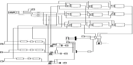
Fig.7. Matlab/Simulink Blocks for Matrix Converter Employing PWM Technique
Figure 7-9 represents the matrix converter unit with PWM modulation technique with and without FLC respectively.
NB NVB NVB NVB NB NM NS Z
NM NVB NVB NB NM NS Z PS
NS NVB NB NM NS Z PS PM
Z NB NM NS Z PS PM PB
PS NM NS Z PS PM PB PVB
PM NS Z PS PM PB PVB PVB
Fig.7. Matlab/Simulink Blocks for Matrix Converter Employing FLC based PWM Technique
Here the PWM pulses are generated by using Embedded Matlab function developed by coding. The input for the embedded MATLAB function is given from the output of the fuzzy logic.
Fig.8. Matlab/Simulink Blocks forpulses Employing FLC based PWM Technique
VI. SIMULATION RESULTS AND DISCUSSION
The proposed control algorithm is tested with an ideal nine-switch three phases to three phase matrix converterfeeding a RL load. For this purpose, digital simulations are carried out using Matlab / Simulink software. The simulation parameters are set as; the supply frequency = 50Hz, the input voltage = 480 V, the input current = 27 A, the switching frequency = 2 kHz, resistance =20 Ω, inductance =310 mH.
Fig.9. Input Voltage and Current Waveform in Steady State Condition
Figure 9 shows the input voltage and current waveformgiven to the matrix converter. The input voltage and current is same for both the modulation techniques.
Fig.11. Output Voltage and Current Waveform of Matrix Converter using PWM Technique
Figure 11 and 12 displays steady state conditions of the simulated output voltage, current waveforms and the harmonic profile of the output voltage.
Fig.12. Harmonic Profile of Output Voltage Employing PWM Technique
It can be seen that both output voltage and current are sinusoidal. The fundamental component of the input current waveform is in phase with the input voltage i.e. the input displacement factor is close to unity likewise same in output current waveform is in phase with the outputvoltage.
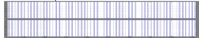
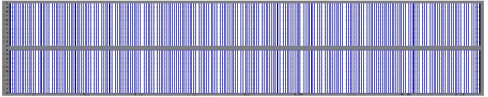
Fig.13. FLC based PWM Pulse for Upper and Lower Switches of Phase A
Figure 13 shows the PWM pulses for upper and lower switches of phase A. Similarly for Phase B and C can be obtained.
Figure 14 displays the steady state conditions of the simulated output voltage, current waveforms of matrix converter using PWM technique employing fuzzy logic controller.
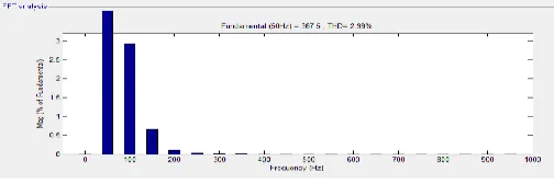
Fig.15. Harmonic Profile of Output Voltage Employing FLC based PWM Technique
Figure 14 displaysthe harmonic profile of the output voltage of matrix converter using PWM technique employing fuzzy logic controller.
TABLE III PERFORMANCE COMPARISION
The detailed analysis revealed that the output line voltage varies with different schemes of these modulationtechniques. The output current in all the three techniques are almost same. PWM has slightly higher value. The simulated values prove that the input and output voltages and currents are sinusoidal. The voltage transfer capability of the matrix converter is approximately 87% for any type of modulation technique. The THD indicates the amount of harmonics present in the system expressed as a percentage. The lower value of THD specifies the lesser harmonics in the output waveform. The THD of the FLC based PWM is lowest under the same switching frequency compared to PWM technique.
VIII. CONCLUSION
The proposed Matrix Converter with differentmodulation techniques was simulated using Matlab/ Simulink model blocks. PWM technique with and without FLC was analyzed in detail and the outputs were presented.The pulses obtained from various schemes are used to control the output parameters of the matrix converter to convert a given three phase input voltage into a three phase output voltage of a desired frequency and magnitude. Simulation result exhibits that the converter has following performance features: Both the input currents and output voltages are pure sine waveforms with the harmonics around or above the switching frequency. The converter is capable of operating at unity power factor. Four quadrant operations are possible. No bulk DC link capacitors are needed, which means that a large capacity, compact converter system can be designed with better efficiency. It has the same voltage transfer ratio capacity as conventional matrix converter. PWM based FLC has the minimum THD level at the output side and hence the reduced losses on the drives. The control circuit to produce pulses is simplest in PWM technique.
REFERENCES
[1] Patrick W.Wheeler, Jose Rodriguez,Jhon C. Clare, Lee paper title Empringham and Alejandro Weinstein, “Matrix Converters: A Technology Review”, IEEE Transactions on Industrial Electronics, Vol.49, Issue 2, pp. 276-288, April 2002.
[2] J.Karpagam, Member IEEE, Dr.A.Nirmal Kumar and V.KumarChinnaiyan, “Comparison of Modulation Techniques for Matrix Converter”, IACSIT International Journal of Engineering and Technology, Vol.2,No.2, April 2010 ISSN: 1793-8236.
S.NO Parameters PWM FLC BASED PWM
1 Output voltage(in volts) 415 367.5 2 Output current(in amperes) 15 13.6
1323,1994.
[6] P. Kirawanich and R. M. O. Connell, “Fuzzy logic control of an active power line conditioner,” IEEE Trans. on Power Electron., vol. 19, no. 6, pp. 1574-1585,2004.