Comparative study of standalone PV systems
for different DC/DC converter topologies of
same specification
Mr. Aravinda M
1, Dr. Padmavathi K
2PG Student [Power Electronics], Dept. of EEE, B.M.S. College of Engineering, Bengaluru, Karnataka, India1 Associate professor, Dept. of EEE, B.M.S. College of Engineering, Bengaluru, Karnataka, India2
ABSTRACT: The main objective of PV standalone systems are to be either a main source or a backup source of electricity in an electricity distribution system. It mainly consists of PV arrays, MPPT controlled DC/DC converter, Battery bank and dump load and/or main loads. Since there are many DC/DC converter topologies are available and each has their own advantages. Here in this paper the results of performance analysis of PV standalone systems realized with different DC/DC topologies using MATLAB/SIMULINK has discussed. Also, the relationship between the terminal voltage of battery bank and maximum power point voltage of PV array, PV array configurations and their loading limitations has explained.
KEYWORDS: Standalone PV system, DC/DC converter, Maximum Power Point.
I.INTRODUCTION
Even though solar energy is not a base source for electricity generation. Nowadays, standalone PV systems are playing a major role to meet the condition uninterrupted power supply for many users like apartments, small scale industries, hospitals, shopping malls etc. The installation of depends on many factors like availability of space for PV panels, capacity of battery bank, amount of load to be served etc. Since, PV cells are constant current sources having limitation of current zero condition after specified terminal voltage i.e. load resistance. The load resistance can’t be changed in real time but the effective resistance of the load seen by the PV cells can be adjusted by using DC/DC converters as interface such that the power extracted from the PV cells is always maximum. But, each DC/DC converter topologies maintains their own relationship between input and output voltages. Hence, it is necessary to analyze these topologies. So the results obtained from simulation study of standalone PV systems having different DC/DC converter topologies and the relationship between maximum power point voltage of PV array, terminal voltage of battery bank and maximum load that can be applied for the system has discussed in next sections
II. SPECIFICATIONS
A. PV MODULE
The PV module mentioned in this paper has 13 PV cells connected in series. The PV cells has the specifications as follows:
Sl.No .
At, A.M=1.5, Gref = 1000 W/m2, Tcell_ref = 38.8 0C = 311.8 K.
1 Voc_ref 0.574 V
2 Vmpp 0.46 V
3 Isc_ref 6.24 A
Sl.No .
At, A.M=1.5, Gref = 1000 W/m2, Tcell_ref = 38.8 0C = 311.8 K.
5 Pmpp 2.644 W
6 Rs_op 0.005 Ω
7 Rsh_op 10 Ω
8 NOCT 43 0C = 316 K
9 A 1.2
10 kv -0.0018 V/K
11 ki 0.065 % A/K
The equations of single diode model for PV module are as follows [1],
Ioutput _op = Iph _op − Id_op Cp− Ish _op ---Eq.1.
Iph _op = Gop
Gref Isc _op---Eq.2.
Isc _op = Isc _ref + ki(Tcell _op− Tcell _ref)---Eq.3.
Tcell _ref = Tair _ref+ NOCT −20
800 Gref---Eq.4.
Tcell _op = Tair _op+ NOCT −20
800 Gop---Eq.5.
Id_op = Irs _ref e
V output _op + Ioutput _op Rs_op
V t_op Cs A − 1 ---Eq.6.
Irs _ref = Irs _op . Tcell _op Tcell _ref
3 . e
1 Tcell _ref−
1 Tcell _op
q E g A k
---Eq.7.
Irs _op =
Isc _op
e V oc _op V t_op A Cs−1
---Eq.8.
Voc _op = Voc _ref + kv(Tcell _op− Tcell _ref)---Eq.9.
Vt_op =
Tcell _op k
q ---Eq.10.
Ish _op =
Voutput _op+Ioutput _opRs _op
Rsh _op ---Eq.11.
Poutput _op = Voutput _opIoutput _op---Eq.12.
Where,
Cs : Number of cells connected in series in a PV module.
Cp : Number of PV modules connected in parellel.
Iph_op : Photo current generated in PV module under operating conditions. (A)
Id_op : Current through internal diode of PV module under operating conditions. (A)
Irs_op : Reverse saturation current of the internal diode in PV module under operating conditions. (A)
Irs_ref : Reverse saturation current of the internal diode in PV module under reference conditions. (A)
Ish_op : Current through the shunt resistance in PV model of module under operating conditions. (A)
Isc_op : Short circuit current of PV module under operating conditions. (A)
Isc_ref : Short circuit current of PV module under reference conditions. (A)
IMPP : Output current of the PV module when it is delivering the maximum power. (A)
Voutput_op : Output voltage of PV module under operating conditions. (V)
Voc_op : Open circuit voltage of PV module under operating conditions. (V)
Voc_ref : Open circuit voltage of PV module under reference conditions. (V)
Vt_op : Thermal voltage of the internal diode in PV module under operating conditions. (V)
VMPP : Output voltage of the PV module when it is delivering the maximum power. (V)
Poutput_op : Output power of PV module under operating conditions. (W)
PMPP : Maximum possible power which can be extracted from PV module. (W)
Gop : Irradiation on PV module under operating conditions. (W/m2)
Gref : Irradiation on PV module under reference conditions. (W/m2)
Tcell_op : Cell temperature under operating conditions. (K)
Tcell_ref : Cell temperature under reference conditions. (K)
Tair_op : Ambient air temperature under operating conditions. (K)
Tair_ref : Ambient air temperature under reference conditions. (K)
NOCT : Normal Operating Cell Temperature. (K)
Rs_op : Effective series resistance of PV module under operating conditions. (Ω) Rsh_op : Effective shunt resistance of PV module under operating conditions. (Ω) A : Ideality factor of the internal diode in PV module.
q : Charge of electron = 1.602 x 10⁻¹⁹C
Eg : Band gap energy in PN junction of PV cell = 1.12eV
K : Boltzmann constant = 1.3806 x 10⁻²³m2kgs-2K-1
ki : Temperature coefficient of output current of PV module. (A/K)
kv : Temperature coefficient of output voltage of PV module. (V/K)
A.M : Air mass coefficient.
B. BATTERY
The battery mentioned in this paper has the specifications as follows: Type: Li-ion
Rating: 3.3 Ah
Terminal voltage, Vbat = 16.8V ( SOC = 100% )
Vbat = 14.8V ( SOC = 60% )
Nominal operating voltage, Vnom = 14.8 V
C. DC/DC CONVERTER
Here, all the topologies are designed [2] for the following specifications and assuming converter is lossless. But during simulation on state resistance and voltage drops in power diodes and power mosfets are considered according to the MATLAB/SIMULINK standards.
Input power = Pin = 52*2.644 W = 137.488 W
Safety factor = 1.2632 Hence, Pin =173.68 W
Output voltage = Vout = Vbat = 14.8 V
Output current = Iout = Pout/Vout = Pin/Vout = 11.73 A
Percentage voltage ripple in capacitor voltage = 𝛿VC = 0.5% = 0.005
Percentage current ripple in the inductor current = 𝛿IL = 5% = 0.05
Operating frequency = f = 30 KHz
The values of inductors and capacitors obtained after designing the different topologies for above mentioned rating are tabulated table.1.
TOPOLOGY L1(µH) L2(µH) C1(µF) C2(µF)
BUCK 420.57 - 33.02 - BOOST 105.14 - 2640 -
BUCK-BOOST
210.28 - 2640 -
CUK 420.64 420.64 33.01 2640 SEPIC 420.64 420.64 2640 2640
TABLE I.
III. RELATIONSHIP BETWEEN MAXIMUM POWER POINT OF THE PV ARRAY AND BATTERY VOLTAGE
Fig.1 Block diagram of standalone PV system
Here,
Input voltage at converter = Vconverter_input = Vpv_output= Output voltage of PV array
Output voltage at converter = Vconverter_output = Vbat
Since the battery voltage will be maintained at the output of the converter, the input voltage can be varied by changing the duty ratio of the control signal. The input voltage has to be maintained at maximum power point voltage to extract maximum power from the PV panels.
i.e. Vpv_output = Voltage corresponds to MPP of PV array = Vpv_output_MPP
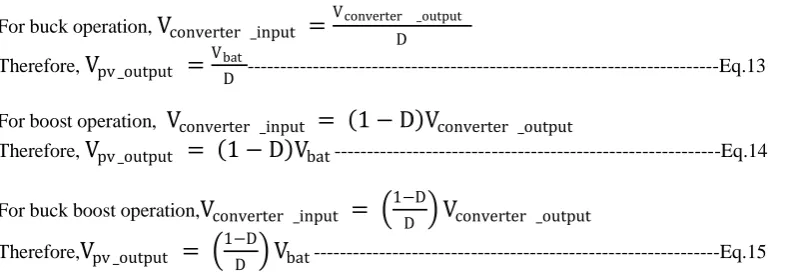
For buck operation,
V
converter _input=
Vconverter _output D Therefore,V
pv _output=
VbatD ---Eq.13
For boost operation,
V
converter _input= 1 − D V
converter _outputTherefore,
V
pv _output= 1 − D V
bat---Eq.14For buck boost operation,
V
converter _input=
1−DD
V
converter _outputTherefore,
V
pv _output=
1−DD
V
bat---Eq.15 For buck operation , select PV array with 𝐕𝐩𝐯_𝐨𝐮𝐭𝐩𝐮𝐭_𝐌𝐏𝐏 = 𝟏. 𝟔𝟕 𝑽𝒃𝒂𝒕---Eq.16
For boost operation , select PV array with 𝐕𝐩𝐯_𝐨𝐮𝐭𝐩𝐮𝐭_𝐌𝐏𝐏 = 𝟎. 𝟒 𝑽𝒃𝒂𝒕 ---Eq.17
For buck boost operation , select PV array with𝐕𝐩𝐯_𝐨𝐮𝐭𝐩𝐮𝐭_𝐌𝐏𝐏 = 𝟎. 𝟔𝟕 𝑽𝒃𝒂𝒕 ---Eq.18
IV. DETERMINING MAXIMUM POWER POINT TRACKING CAPABILITY OF BUCK, BOOST AND BUCK-BOOST OPERATIONS.
FOR BUCK OPERATION,
We know that [3] ,
Voutput _converter = D. Vconverter _input = D. Vpv _output
Ioutput _converter =
Iconverter _input
𝐷 =
Ipv _output 𝐷
Therefore,
Rout = 𝐷2. 𝑅𝑖𝑛
Where,
Rout = Effective output resistance seen at converter output, Ω
Rin = Effective input resistance seen by PV array, Ω
Hence,
𝑅𝑖𝑛 = 𝑅𝑜𝑢𝑡
𝐷2 ---Eq.19
But for buck operation in order to achieve the condition mentioned in eq.16 and each PV cell can provide 2.644W at 0.46V and 5.748A. This requires a string with 53.73 cells in series. Hence 4 modules are connected in series. (Each module has 13 cells in series)
Therefore,
𝑅𝑖𝑛 _𝑀𝑃𝑃 =
𝑉𝑝𝑣 _𝑜𝑢𝑡𝑝𝑢𝑡 _𝑀𝑃𝑃 𝐼𝑝𝑣 _𝑜𝑢𝑡𝑝𝑢𝑡 _𝑀𝑃𝑃
𝑅𝑖𝑛 _𝑀𝑃𝑃 =
(0.46 × 13 × 4) (5.748) 𝑅𝑖𝑛 _𝑀𝑃𝑃 = 4.1614 Ω
Where,
Rin_MPP = Effective input resistance seen by PV array at MPP , Ω
Vpv_output_MPP = Output voltage at terminal of PV array at MPP , V
Ipv_output_MPP = Output current delivered by PV array at MPP , A
Hence,
The maximum effective resistance that can be seen by converter at output beyond which it is not possible to track the maximum power from the source, Rout_max can also be calculated by,
Rout _max = 𝐷𝑚𝑎𝑥2. 𝑅𝑖𝑛 _𝑀𝑃𝑃 Rout _max = 0.92× 4.1614 Rout _max = 3.37 Ω
Where,
Rout_max = Maximum effective output resistance seen by converter output beyond which tracking MPP is not possible, Ω
It can be seen that as Rout crosses 3Ω. The range of upper limit of the duty cycle crosses 0.9 and hence it is not possible
SIMILARLY FOR BOOST OPERATION,
𝑅𝑖𝑛 = (1 − 𝐷)2. 𝑅𝑜𝑢𝑡 ---Eq.20
And to achieve the condition mentioned in eq.17 requires a string with 12.86 cells in series. And total number of cells is 52 , we can have four modules in parallel.
Therefore,
𝑅𝑖𝑛 _𝑀𝑃𝑃 = 0.26 Ω
And,
Rout _max = 29 Ω
SIMILARLY FOR BUCK-BOOST OPERATION
𝑅𝑖𝑛 = 1−𝐷
𝐷 2
. 𝑅𝑜𝑢𝑡 ---Eq.21
And to achieve condition mentioned in eq.18 requires a string with 21.55 cells in series. And total number of cells is 52 , we can have two modules in series and together parallel to two more modules connected in series.
Therefore,
𝑅𝑖𝑛 _𝑀𝑃𝑃 = 1.04 Ω
And,
Rout _max = 84.24 Ω
V. RESULT AND DISCUSSION
Few major factors to be considered while designing a standalone PV systems are compared by the help of simulations and using the relationship which are discussed in above sections. They are as follows,
SERIES PARALLEL SERIES-PARALLEL
VPV_OUTPUT_MPP 23.92 V 5.98 V 11.96 V
IPV_OUTPUT_MPP 5.748 A 22.992 A 11.496 A
PPV_OUTPUT_MPP 137.4921 W 137.4921 W 137.4921 W
RIN_MPP 4.1614 Ω 0.26 Ω 1.04 Ω
ROUT_MAX 3.37 Ω 29 Ω 84.24 Ω
D
Settling time, ts (milli Seconds)
Load=1.26Ω , Filter capacitance=330µF Buck Boost
Buck-Boost
Cuk SEPI C
0.1 29 2.06 2.9 52 93
0.3 4.4 3 3.7 27 116
0.5 3.34 4.9 5.65 90 75
0.6 2.92 - 10 70 89
0.65 7.86 - 9.3 45 48
0.7 6.4 10.8 25 60 70
0.75 - 9.4 35 53 70
0.8 2 10.2 33 56 67
0.85 25 - 35 61 75
0.9 34 29 32 58 52.8
TABLE III. COMPARISION OF PARAMETERS OF DC/DC CONVERTER
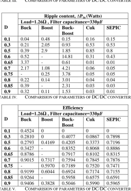
D
Ripple content, ∆Pin (Watts)
Load=1.26Ω , Filter capacitance=330µF Buck Boost
Buck-Boost
Cuk SEPIC
0.1 0.04 0.48 0.15 0.16 0.15 0.3 0.21 2.05 0.93 0.53 0.53 0.5 0.39 2.9 1.85 0.85 0.8 0.6 0.52 - 14.81 0.31 0.43 0.65 3.37 - 0.61 0.01 0.01 0.7 2.17 1.08 4.21 0.06 0.05 0.75 - 0.25 3.78 0.05 0.05 0.8 0.22 0.14 3.01 0.04 0.04 0.85 0.39 - 2.31 0.03 0.03 0.9 0.32 0.11 1.53 0.03 0.01
TABLE IV. COMPARISION OF PARAMETERS OF DC/DC CONVERTER
D
Efficiency
Load=1.26Ω , Filter capacitance=330µF Buck Boost
Buck-Boost
Cuk SEPIC
0.1 0.4524 0 0 0 0
0.3 0.2810 0 0.4077 0.0867 0.7898 0.5 0.2793 0.4169 0.4205 0.3373 0.7196 0.6 0.3427 - 0.8352 0.8068 0.8886 0.65 0.8786 - 0.7917 0.8102 0.8315 0.7 0.9015 0.7317 0.7594 0.7845 0.7876 0.75 - 0.5970 0.7189 0.7520 0.7471 0.8 0.9199 0.6044 0.6924 0.7174 0.7155 0.85 0.9264 - 0.5958 0.6575 0.6591 0.9 0.9406 0.3828 0.5046 0.5990 0.5965
Parameter
Topology
Load=1.26Ω , Filter capacitance=330µF Buck Boost
Buck-Boost
Cuk SEPIC
DMPP 0.8 0.75 0.65 0.65 0.65
Vpv_output_MPP 23.02 5.86 11.8 11.75 11.79
Ipv_output_MPP 5.96 21.74 11.99 11.56 11.6
Ppv_output_MPP 137.1 127.3 141.48 135.83 136.76
Vconverter_output 17.64 17.71 -17.78 -17.75 17.77
Iconverter_output 7.155 4.295 -6.3 -6.2 6.4
Pconverter_output 126.2 76.06 112.01 110.05 113.72
Vbat = Vload 17 16.88 -16.94 -16.95 16.92
Ibat 6.34 9.151 -7.758 -7.578 7.493
Pbat 107.7 154.4 131.42 128.44 126.78
Iload 13.49 13.44 -14.05 -13.77 13.893
Pload 229.4 226.9 238.14 233.53 235.06
ts 2 9.4 9.3 45 48
∆Pin 0.22 0.25 0.61 0.01 0.01
Pin_peak 136.4 136.4 136.4 136.4 136.4
Efficiency 0.919 0.597 0.7917 0.8102 0.8315 Rin 3.862 0.269 0.9841 1.0164 1.0163
Rout 2.465 4.123 2.8223 2.8629 2.7765
TABLE VI. COMPARISION OF PARAMETERS OF OVER ALL STANDALONE PV SYSTEM AT MPP
VI.CONCLUSION
From the above study it can be concluded that standalone systems with,
Series-Parallel PV array has greater loading capability compare to parallel and series connected arrays. And parallel PV arrays has greater loading capability compare to series connected arrays.
To use Buck converter the MPP voltage of PV array should be greater than terminal voltage of the battery. To use Boost converter the MPP voltage of PV array should be less than terminal voltage of the battery. To use Buck-Boost, Cuk, SEPIC converter the MPP voltage of PV array is independent of terminal voltage of
the battery.
If the user wants to expect the MPP at particular value of duty ratio. Then the PV array and the battery has to be selected properly depending on the selected DC/DC converter topology.
At MPP, for a similar design specifications the output of buck converter has lesser settling time compare to other topologies. SEPIC has better efficiency and less power ripple.
When the overall system is considered, Buck-Boost, Cuk and SEPIC has tracked the maximum power close to the duty cycle for which they have designed. The power tracked by Buck-Boost converter is highest.
REFERENCES
[1] Dominique Bonkoungou et.al. “Modelling and simulation of photovoltaic module considerung single-diode equivalent circuit model in
MATLAB” IJETAE, volume 3, March 2013.
[2] Danial w. Hart “ Power Electronics “. Tata McGraw-Hill publications.