Sensitivity Increases for the TITAN Decay Spectroscopy Program
K.G. Leach1,2,a, A. Lennarz1,3, A. Grossheim1, C. Andreoiu2, J. Dilling1,4, D. Frekers3, M. Good1, and S. Seeraji2
1TRIUMF, 4004 Wesbrook Mall, Vancouver BC, V6T 2A3, Canada
2Department of Chemistry, Simon Fraser University, Burnaby BC, V5A 1S6, Canada 3Institüt für Kernphysik, Westfalische-Wilhelms-Universität Münster, D-48149, Germany
4Department of Physics and Astronomy, University of British Columbia, Vancouver, BC, V6T 1Z1, Canada
Abstract.The TITAN facility at TRIUMF has recently initiated a program of performing decay spectroscopy measurements in an electron-beam ion-trap (EBIT). The unique environment of the EBIT provides backing-free storage of the radioactive ions, while guiding charged decay particles from the trap centre via the strong magnetic field. This measurement technique is able to provide a significant increase in detection sensitivity for photons which result from radioactive decay. A brief overview of this device is presented, along with methods of improving the signal-to-background ratio for photon detection by reducing Compton scattered events, and eliminating vibrational noise.
1 Introduction
TRIUMF’s Ion Trap for Atomic and Nuclear Science (TI-TAN) [1] is located at the Isotope Separator and Accelera-tor (ISAC) facility at TRIUMF, in Vancouver, BC, Canada. TRIUMF-ISAC produces rare-isotope beams (RIBs) us-ing the isotope separation on-line (ISOL) technique [2], by generating spallation reactions on thick production tar-gets using an up to 100μA beam of 500 MeV protons. The mass-selected, continuous beam of radioactive ions is delivered at low energies (∼20 keV) to a suite of experi-mental facilities for both cooled- and stopped-beam exper-iments [3].
The TITAN system consists of three ion traps: a buffer-gas-filled radio-frequency-quadrupole (RFQ) [4], a 3.7 T Penning-trap for precision mass measurements (MPET) [5], and an electron-beam ion trap (EBIT) [6] which provides highly charged ions (HCIs) for the Pen-ning trap. The addition of two new components to the TITAN system is planned for the near future; a cooler Penning-trap (CPET) to sympathetically cool HCIs with electrons or protons [7], and a multi-reflection time-of-flight (MR-ToF) isobar separator [8]. Both of these de-vices have been delivered to TRIUMF and should be in-stalled in the TITAN system within the next year.
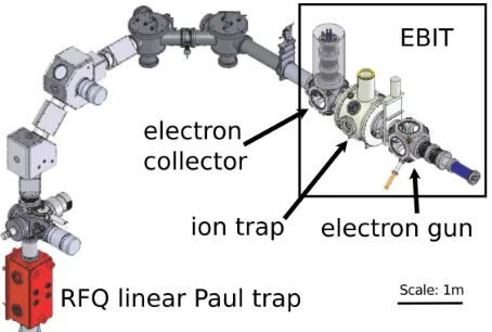
The TITAN facility is primarily used to perform high-precision Penning-trap mass spectrometry on short-lived radioactive nuclides [9–12]. TITAN has also recently ini-tiated an extensive experimental program of performing in-trap decay spectroscopy with the EBIT [13–16]. A schematic view of the TITAN facility at TRIUMF dur-ing decay-spectroscopy experiments is displayed in Fig. 1. This article presents a brief description of the decay
spec-ae-mail: [email protected]
Figure 1. A schematic view of the ion traps used in the TI-TAN decay spectroscopy program. The ions are extracted in a bunch from the RFQ and injected as singly charged ions to the EBIT where they are stored for charge breeding and decay spec-troscopy. After the ions have been stored in the EBIT, they are extracted and dumped downstream away from the detectors. The ion-bunch cycling is repeated continuously over the course of an experiment.
troscopy program at TITAN, as well as recently employed methods of improving the overall photon detection sensi-tivity.
2 Decay Spectroscopy Overview
The TITAN EBIT features seven external access ports which allow for the mounting of photon detectors for per-forming spectroscopy on trapped ions. These ports are covered with 0.25 mm thick, > 99% pure, pinhole-free DOI: 10.1051/
C
Owned by the authors, published by EDP Sciences, 2015 /201 0 0 ( 2015)
epjconf EPJ Web of Conferences ,
0 0 59 93
3 06
06 7
7
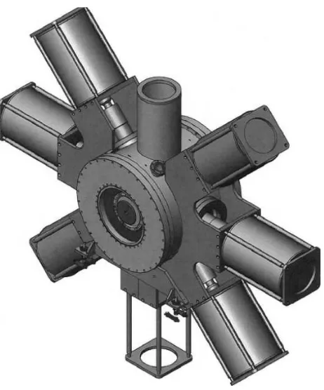
Figure 2.The decay-spectroscopy setup surrounding the TITAN EBIT. Shown are six of the seven detectors (the bottom housing is empty for illustrative purposes) which are supported by an alu-minum frame which is attached to the trap. It is at this connection point where the vibrational noise from the EBIT is transferred to the Si(Li) detectors.
Be windows to provide vacuum isolation, while having a minimal effect on X- andγ-ray transmission. For the present physics goals [17], each of the seven access ports around the EBIT houses a lithium-drifted silicon (Si(Li)) detector [16]. The particular energy region of interest is
Eγ≤50 keV, where X-rays from the electron capture (EC) decay process can be observed. Since these energies corre-spond to low-amplitude signals from the Si(Li) detectors, a high level of environmental control is needed to reach the sensitivity required for the observation of weak transi-tions.
3 Vibrational-Noise Reduction
The EBIT employs a helium cryo-cooler for the supercon-ducting magnet which supplies high-pressure He gas to the cold-head [6]. In this process, the compression cylinder generates vibrational noise. The photon detectors are lo-cated in a frame that is directly mounted to the base of the magnet housing, which transfers the vibrational noise gen-erated by the He compressor directly to the Si(Li) detec-tors (Fig. 2). These vibrations resonate at many frequen-cies in the aluminum detector-support frame and generate acoustic noise up to several-hundred Hz. The distribution of high-frequency vibrations that exist at one of the hori-zontal access ports is presented in Ref. [16]. These vibra-tions have a significant effect on the signal quality from
Figure 3.A design drawing of a Si(Li) detector in its mounting structure. Vibration isolation material is located at each contact point, including the front- and back-plates, as well as a “clam-shell" structure on the sides. This new housing design for the Si(Li) detectors also improves the versatility of the array, allow-ing for easier interchangeability between photon detector types.
the Si(Li) detectors, primarily on the observed energy res-olution. The following section presents tests of different damping materials for possible vibration-reduction solu-tions.
Two primary materials were tested for vibration damping and isolation purposes; PolytechR High
Den-sity Polyurethane foam-grade 40 (PHU-40) [18], and
POLYFORMR High Density Molded - Non-Skinned
(PHDM-NS) Polyurethane Foam [19]. The PHU-40 ma-terial is is a low modulus, open cell Polyurethane foam which exhibits a low compression set, excellent impact resistance, and low permeability when compressed [18]. The PHDM-NS material is a flexible foam that is char-acterized by its high resilience, good tear strength, and good elongation properties [19]. These materials were se-lected due to their excellent properties for vibration isola-tion while under long-term compression.
In order to properly assess the effect of the two isola-tion materials, detector performances were tested with a
133Ba source, in four different environments:
1. Off-Trap: The detector was removed from the trap and placed on a test bench in the ISAC experimen-tal hall. The results of tests in this environment are considered as the nominal performance.
2. No Damping: The detector was mounted in its housing on the trap with no material between the detector and its mounting points. This configuration is how all previous measurements were performed.
600 800 1000 1200 1400 1600
48 50 52 54 56 58 60
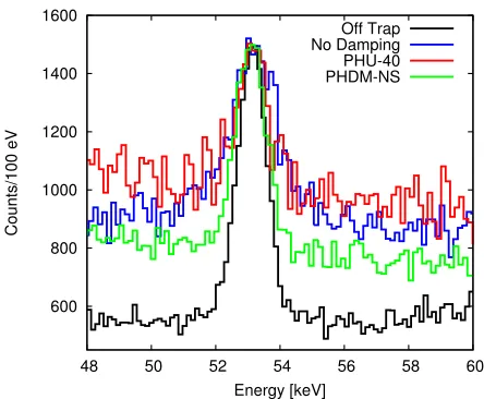
Counts/100 eV Energy [keV] Off Trap No Damping PHU-40 PHDM-NS
Figure 4.A comparison of the observed133Ba decay spectra for Detector-427 renormalized by peak height to highlight the res-olution difference at 53 keV. The large peak-to-background dif-ference for the “Off-Trap" data results from a larger solid-angle coverage of the test bench setup relative to the “On-Trap" tests. The list of resulting resolutions for all five detectors is displayed in Table 1.
the detector and its mounting points, as shown in Fig. 3.
4. PHDM-NS: The detector was mounted in its hous-ing on the trap with the PHDM-NS material [19] between the detector and its mounting points, as shown in Fig. 3.
For each test, the Si(Li) detectors were mounted in a horizontal port on the EBIT, and a collimated133Ba source
was placed in the port on the opposite side of the trap. Al-though this significantly extended the measurement peri-ods required due to the small solid-angle coverage, it was necessary since there is no way of accessing the centre of the trap for calibration purposes (c.f. Ref. [16]). Both ma-terials were tested on five of the seven detectors and pared to the detector performance on a test bench. A com-parison of the resulting133Ba decay spectra is displayed in Fig. 4 for one of the five detectors, and the quantitative comparison for all five detectors is shown in Table 1.
4 Active Compton Suppression
An increase in detection sensitivity is also possible through the elimination of Compton scattered events in the Si(Li) detectors. This background is generated when the emitted photon interacts with the detector, but does not deposit all of its energy in the crystal, and exits the volume. The most common method for active Compton background suppression uses a scintillating material with a high nuclear charge (Z) that surrounds the photon detector. This method improves the effective signal-to-background ratio by vetoing events with incomplete energy deposition in the Si(Li) crystal. Typically, the inorganic scintillating
Table 1.The effect of both damping materials on the observed resolution of the 53 keVγ-ray following the decay of133Ba for five Si(Li) detectors, as described in the text. The resolution values are given as full-width at half-maximum (FWHM). In nearly all cases, the nominal resolution vales are achieved using
the vibration isolation material PHDM-NS, as highlighted in bold.
Det. Off-Trap No Damp. PHU-40 PHDM-NS
No. (%) (%) (%) (%)
404 1.6(1) 1.9(1) 1.7(1) 1.6(1) 427 2.0(1) 3.5(1) 2.4(1) 2.1(1) 431 2.0(1) 2.8(1) 2.7(1) 2.4(1) 432 2.1(1) 2.7(1) 2.2(1) 2.0(1) 438 1.9(1) 2.4(1) 2.4(1) 2.2(1)
crystal Bismuth Germanium Oxide (BGO) is used in com-bination with photo-multiplier tubes (PMTs) to achieve this suppression [21]. The TITAN EBIT, however, poses a considerable problem since PMTs are unable to operate in the up to∼ 0.15 T fringe magnetic fields. To circumvent this issue, development has begun to couple the BGO crys-tals to silicon photo-multipliers (SiPMs) instead of PMTs, which are able to operate in a high-field environment. In the current design (Fig. 5), the SiPMs are individually cou-pled to eighteen 1 cm thick bars of BGO which surround the Si(Li) detector. This ensures optical isolation of the in-dividual components, as well as decreasing the overall size of the crystals needed. Using this design, a factor of 2-4 suppression of Compton-generated background at low en-ergies has been demonstrated in Monte-Carlo-based simu-lations (Fig. 6). Further work on the electronic readout of the SiPMs is required before it can be effectively coupled to the BGO crystals (due to their low light output), and is presently underway [22].
5 Conclusions
In summary, an in-trap decay spectroscopy tool has been developed at TRIUMF using TITAN’s electron-beam ion-trap. The ion-trap environment allows for the detection of low-energy photons by providing backing-free stor-age, while simultaneously guiding charged decay particles away from the trap centre via the strong magnetic field. To further increase the scientific reach of this facility, two studies were performed to improve the overall sensitivity for photon detection.
Figure 5. A concept design of an active Compton suppression shield solution for the Si(Li) detectors. The shield itself sits in-side the flange on the outin-side of the EBIT access ports, and each consists of 18 long BGO crystals which surround the detector radially. The SiPM assembly also includes a Peltier cooling el-ement to keep the thin matrix at temperatures just above 0◦C to reduce dark noise effects. The detector assembly shown in Fig. 3 inserts directly into the suppression shield such that the Si(Li) crystal is a few mm away from the thin Be window on the ex-terior of the EBIT. This design concept could also be employed for other types of photon detectors that could be coupled to the system in the near future [16].
is currently underway, and will provide a significant im-provement for both photon detection sensitivity and en-ergy resolution.
Acknowledgements
TRIUMF receives federal funding via a contribution agreement with the National Research Council of Canada (NRC). This work was partially supported by the Natu-ral Sciences and Engineering Research Council of Canada (NSERC), and the Deutsche Forschungsgemeinschaft (DFG) under grant FR 601/3-1. The authors would also like to thank Fabrice Retiére and the TRIUMF Science Technology Department for their collaborative effort in de-velopment of the SiPM detectors. KGL thanks Stephan Ettenauer and Thomas Brunner for useful discussions re-garding this work.
References
[1] J. Dillinget al., Int. Journ. Mass Spec.251, 198 (2006) [2] Y. Blumenfeldet al., Phys. Scr. T152, 014023 (2013) [3] J. Dillinget al., Hyper. Inter.225, 1 (2014)
[4] T. Brunneret al., Nucl. Instrum. Methods Phys. Res. A676, 32 (2012)
0
20
40
60
80
100
120
Energy (keV)
0
250
500
750
1000
1250
1500
1750
Counts per 100 eV
Unsuppressed
Suppressed
Sn, Cs, and Xe
x-rays
Factor
of 4
Supp.
57.9 keV
89.4 keV
96.5 keV
120.2 keV
102.7 keV
53.9 keV
Figure 6. Ageant4 [20] simulation showing the effect of ac-tive Compton suppression with BGO shields, as described in the text. The simulated curves results from the same number of events from one detector during the commissioning124Cs exper-iment [15], where the red curve is the result for passive Cu and Pb shields only, and the black line is Compton suppressed pho-ton spectrum using 1 cm of BGO surrounding the detector. The black bar demonstrates the factor-of-four Compton background suppression at 10 keV.
[5] M. Brodeur et al., Int. Journ. Mass Spec. 310, 20 (2012)
[6] A. Lapierreet al., Nucl. Instrum. Methods Phys. Res. A624, 54 (2010)
[7] B.E. Schultzet al., Phys. Scr.T156, 014097 (2013) [8] W.R. Plaß et al., Int. Journ. Mass Spec. 349, 134
(2013)
[9] A.T. Gallantet al., Phys. Rev. Lett.113082501 (2014) [10] D. Frekerset al., Phys. Lett. B722, 233 (2013) [11] A.T. Gallant et al., Phys. Rev. Lett. 109, 032506
(2012)
[12] M. Brodeur et al., Phys. Rev. Lett. 108, 212501 (2012)
[13] S. Ettenaueret al., AIP Conf. Proc.1182, 100 (2009) [14] T. Brunneret al., Eur. Phys. J. A49, 142 (2013) [15] A. Lennarzet al., Phys. Rev. Lett.113082502 (2014) [16] K.G. Leachet al., Nucl. Instrum. Methods Phys. Res.
A (submitted); arXiv:[nucl-ex]1405.7209 (2014) [17] D. Frekerset al., Can. J. Phys.85, (2007) 57-75 [18] PolytechR High Density Polyurethane foam grade
40Technical Data Sheet, Polymer Technologies Inc., (2014)
[19] POLYFORMR High Density Molded - Non-Skinned (PHDM-NS) Polyurethane Foam Technical Data Sheet, Polymer Technologies Inc., (2014) [20] S. Agostinelliet al., Nucl. Inst. and Meth. Phys. Res.
[21] Glenn F. Knoll, Radiation Detection and Measure-ment. John Wiley and Sons Inc., 3rdEdition (2000)
![Figure 6. A geant4 [20] simulation showing the effect of ac-tive Compton suppression with BGO shields, as described inthe text](https://thumb-us.123doks.com/thumbv2/123dok_us/8178665.1365934/4.595.313.535.65.289/figure-simulation-showing-eect-compton-suppression-shields-described.webp)
