ISSN (Print) : 2320 – 3765 ISSN (Online): 2278 – 8875
I
nternational
J
ournal of
A
dvanced
R
esearch in
E
lectrical,
E
lectronics and
I
nstrumentation
E
ngineering
(A High Impact Factor, Monthly, Peer Reviewed Journal)
Website: www.ijareeie.com
Vol. 7, Issue 5, May 2018
Development of Novel Embedded Controller
for Safe Landing of UAV
Vidyashree S1, Dhanalakshmi L2, Siva Subba Rao Patange 3, S Raja 4
PG Student, Dept of ECE, Bangalore Institute of Technology, Bengaluru, India 1 Assistant Professor, Dept of ECE, Bangalore Institute of Technology, Bengaluru, India 2 Principal Scientist, Dept of STTD,CSIR-National Aerospace Laboratories, Bengaluru, India 3
Chief Scientist, Dept of STTD,CSIR-National Aerospace Laboratories, Bengaluru, India 4
ABSTRACT: This paper demonstrates that development of novel embedded controller for safe landing of UAV. UAV (Unmanned Aerial Vehicle) commonly known as drone MAV (Micro aerial Vehicle) is a class of miniature UAVs having size restriction. Used in many applications for defense purpose, crowd areas etc. The work is caused by using five ultrasonic sensors placed in all direction right, left, front, back and towards ground. As the detection range is 400 cm. Four sensors are used for landing purpose and covered an area at an angle of 30 0. These sensors are connected to Arduino uno microcontroller board. Pixhawk is a flight controller board used in this experiment this can be interfaced with Arduino microcontroller board through UART. The command is requested from RC transmitter to auto land safely using microcontroller board attached to the MAV vehicle. The ultrasonic sensor shows different value that can be corrected by tuning PID values which are adjusted by physically RC transmitter. After recheck the ultrasonic sensor shows the same value from all the sensor then the vehicle is said to be stable condition then its stop the motor and landing. This algorithm has successfully implemented. Results are seen in Arduino IDE.
KEYWORDS: Ultrasonic Sensor, Arduino uno Microcontroller board, Pixhawk autopilot board, servo motor, ESC, Arduino IDE, Mission planner, transceiver.
I. INTRODUCTION
UAV (Unmanned Aerial Vehicle) commonly called as drone come in different shapes and sizes. Each of these has their own distinct pros and cons. UAV is an aircraft usually flied without human pilot. These are large in size MAV (Micro aerial Vehicle) is a class of miniature UAVs having size restriction The MAV classified into three types namely fixed wing, rotary wing, flapping wing. Rotary wing quadcopter is used for safe landing application by avoiding strike landing. Because vertical take off and take land (VTOL) is the main advantage of rotary wing. The Aim of project is to develop an embedded controlled autopilot system for MAV application using Pixhawk board for safe landing.
II HARDWARE AND SOFTWARE
2.1 Ultrasonic sensor (HC-SRO4)
ISSN (Print) : 2320 – 3765 ISSN (Online): 2278 – 8875
I
nternational
J
ournal of
A
dvanced
R
esearch in
E
lectrical,
E
lectronics and
I
nstrumentation
E
ngineering
(A High Impact Factor, Monthly, Peer Reviewed Journal)
Website: www.ijareeie.com
Vol. 7, Issue 5, May 2018
Figure 1 shows ultrasonic sensor module HCSR04 used in safe landing purpose. This sensor having unique feature hit and bounce property. The ultrasonic sensor can helps to identify the obstacles presents and also measuring distance. This sensor can be calculate the distance by using distance formula distance = time * speed.
Specifications of HCSR04
Working voltage DC 5 V
Working current 15 ma Working frequency 40 kHz
Max range 4 m
Min range 2 cm
Measuring angle 15 degree Trigger input signal 10 us TTL pulse Echo output signal Input TTL level signal
and range in proportion
2.1Arduino Uno microcontroller
Figure 2: The arduino uno board
The figure 2 shows Arduino Uno microcontroller board based on ATmega 328 processor. Having 14 digital input/output pins and 6 analog input pins. It can be connected by using USB cable through laptop or power battery. The recommended voltage is 7 to 12 V. The ATmega 328 processor is a low power CMOS 8 bit microcontroller and having RISC architecture. Easily we can dump the code in a microcontroller board. The Arduino board having separate power pins, analog pins, digital pins, and LED pin.
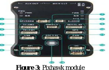
2.2 Pixhawk autopilot board
Figure 3: Pixhawk module
ISSN (Print) : 2320 – 3765 ISSN (Online): 2278 – 8875
I
nternational
J
ournal of
A
dvanced
R
esearch in
E
lectrical,
E
lectronics and
I
nstrumentation
E
ngineering
(A High Impact Factor, Monthly, Peer Reviewed Journal)
Website: www.ijareeie.com
Vol. 7, Issue 5, May 2018
is used for measure the speed of the vehicle. Barometer is used for measure the pressure of vehicle and magnetometer helps to find the height of the vehicle from ground station is as shown in figure 3
2.3 Servo motor
Figure 4: Brushless DC motor
Figure 4 shows brushless DC motor The brushless DC motor is commonly known as electrical commutated motors. Brushed less DC motor has well known function of brushed motor. It has high power high speed and highly controlled device. The brushless DC motor having stator and rotor its working is same as a brushed DC motor. And having internal shaft feedback. It have permanent magnets rotate around fixed armature.
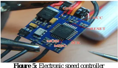
2.5 Electronic Speed Controller (ESC)
Figure 5: Electronic speed controller
Figure 5 shows electronic speed controller. The electronic speed controller is configured with flight controller board with normal PWM inputs so that it matches the expected working. Input voltage to be given 2-4 cells Lithium Polymer/ Lithium Ion battery. It supplies 5 V, 3 A for external receiver and servos. The ESC is connected to servo motor in order to increase the speed of the motor the motor connected roll and pitch movement for vehicle in clock wise and anti-clockwise direction respectively.
2.4 Arduino IDE software
ISSN (Print) : 2320 – 3765 ISSN (Online): 2278 – 8875
I
nternational
J
ournal of
A
dvanced
R
esearch in
E
lectrical,
E
lectronics and
I
nstrumentation
E
ngineering
(A High Impact Factor, Monthly, Peer Reviewed Journal)
Website: www.ijareeie.com
Vol. 7, Issue 5, May 2018
Arduino IDE is an open source project to which ATmega chips connect it. In the software the code is written and uploaded to any ATmega chip and then the code is executed on the chip. Many 3D printer electronics and Arduino compatible use ATmega chip. Sketch is the window in which the program is to be written which is shown in figure 6 Arduino programs can be devided into three main parts namely structure, values, functions.
2.6 Mission planner
Mission planner is software present in the ground station. It is connected to the RC transmitter by set the baud rate and is connected to the MAV auto pilot board the mission planner having different section durinf flight. The Autopilot board can monitor the vehicle and can be seen in ground station.depending the MAV can be select the frame types. Calibration of sensors is required before any mission is started and the RC transmitter is also calibrated for pitch, roll and yaw movements. The mission planner consists of three windows: head-up display, control area, map area. The mission planner software is as shown in figure 7.
Figure 7: Window showing mission planner.
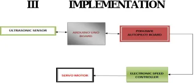
III IMPLEMENTATION
Figure 8 Block diagram of safe landing
ISSN (Print) : 2320 – 3765 ISSN (Online): 2278 – 8875
I
nternational
J
ournal of
A
dvanced
R
esearch in
E
lectrical,
E
lectronics and
I
nstrumentation
E
ngineering
(A High Impact Factor, Monthly, Peer Reviewed Journal)
Website: www.ijareeie.com
Vol. 7, Issue 5, May 2018
FLOW DIAGRAM for SAFE LANDING
Figure 9: Algorithm for safe landing
The figure 9 shows an algorithm for safe landing for UAV. The flow diagram explains the path followed to execute safe landing by avoiding crash land. In first step the initial values is obtained from ultrasonic sensor placed in all direction. The signal can transmit from transmitter module of ultrasonic sensor and reflects back from ultrasonic receiver. The altitude height of the land is obtained from barometric sensor and altimeter. The RC transmitter is helps to control the MAV during the mission. The command can be requested from RC transmitter is given to auto land safely to the microcontroller board attached to the MAV vehicle. If the sensors shows unequal distances then it can be corrected by tuning PID values after recheck the value then vehicle gets stabilized position and stop the motor then its landing on the ground.
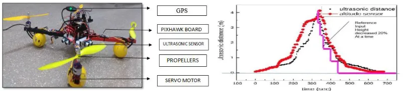
IV. RESULTS AND DISCUSSION
Figure 10: Experimental setup of hardware
ISSN (Print) : 2320 – 3765 ISSN (Online): 2278 – 8875
I
nternational
J
ournal of
A
dvanced
R
esearch in
E
lectrical,
E
lectronics and
I
nstrumentation
E
ngineering
(A High Impact Factor, Monthly, Peer Reviewed Journal)
Website: www.ijareeie.com
Vol. 7, Issue 5, May 2018
V. CONCLUSION
The algorithm has been developed and suitable for autopilot system in order to avoid crash landing and safely, smoothly landing on the earth. By using ultrasonic sensors on the controller for safe landing was checked. This experiment was successfully done and performed.
ACKNOWLEDGEMENT
The authors would like to thank the Director, Mr. Jitendra J Jadhav CSIR-National Aerospace Laboratories for his persistence to carry out the work and Dr. Satish Chandra, Head Structural Technologies Division (STTD) for providing all the facilities for completing this work. My Special thanks to Mr. Aravindu B, Technical officer, Structural Technologies Division (STTD), CSIR-National Aerospace Laboratories, for their help.
REFERENCES
[1] Sergio Chiesa, Sara Cresto Aleina, Giovanni Antonio Di Meo, Roberta Fusaro, “Autonomous Take-Off and Landing for Unmanned Aircraft System: Risk And Safety Analysis”, 29TH Congress Of The Council Of Aeronautical Sciences.
[2] Ardupilot.org/planner/docs/mission-planner-overview.html
[3] P. Riseborough, “Automatic Take-Off and Landing Control for Small UAV’s”.
[4] Pankaj Akuala, Ananda CM Dr Cm, “IR and Ultrasonic Sensors Characterization to aid in Atitude estimation during landing of MAV”, 3rd International Conference on Recent Advances in Design, Development and Operation of MAV.
[5] Kirtan Gopal Panda, Deepak Agrawal, Arcade Nshimiyimana, Ashraf Hossain, “The effects of environment on accuracy of ultrasonic sensor operates in millimetre range”, 20 february 2016.
[6] Rajan P Thomas, Jithin K K, Hareesh K S, Habeeburahman C A, Jithin Abraham,“ Range Detection based on Ultrasonic Principle”, February 2014.
[7] Ultrasonic ranging module HC-SR04 datasheet [online] accessed on 23/08/2016
http://users.ece.utexas.edu/~valvano/Datasheets/HCSR04b.pdf
[8] Kirillshilov*, “The next Generation Design of Autonomous MAV flight control system smartAP”, department of aeromechanical and flight engineering.
[9] Dr. Robert H. Klenke, professor of electrical and computer engineering, “ A low cost implementation of autonomous takeoff and lading for a fixed wing UAV”, virginia commonwealth University, 2014.
[10] Karl E. Wenzel and Andreas Zell, “ Automatic Takeoff, Hovering and Landing control for Miniature Helicopters with Low-Cost onboard Hardware”, university to tubingen, department of computer science, sand 1, 72076 tubingen.
[11] Sergio Chiesa, Sara Cresto Aleina, Giovanni Antonio Di Meo, Roberta Fusaro, “Autonomous Take-Off And Landing For Unmanned Aircraft System: Risk And Safety Analysis”, 29TH Congress Of The Council Of Aeronautical Sciences.
[12] Kirtan Gopal Panda, Deepak Agrawal, Arcade Nshimiyimana, Ashraf Hossain, “The effects of environment on accuracy of ultrasonic sensor operates in millimetre range”, 20 february 2016.