R E S E A R C H
Open Access
Multi-carrier modulation analysis and
WCP-COQAM proposal
Hao Lin
*and Pierre Siohan
Abstract
In the vision towards future radio systems, where access to information and sharing of data is to be available anywhere and anytime to anyone for anything, a wide variety of applications and services are therefore envisioned. This naturally calls for a more flexible system to support. Moreover, the demand for drastically increased data traffic, as well as the fact of spectrum scarcity, would eventually force future spectrum access to a more dynamic fashion. For addressing the challenges, a powerful and flexible physical layer technology must be prepared, which naturally brings us to the question whether the legacy of the OFDM system can still fit in this context. In fact, during the past years, extensive research effort has been made in this area and several enhanced alternatives have been reported in the literature. Nevertheless, up to date, all of the proposed schemes have advantages and disadvantages. In this paper, we give a detailed analysis on these well-known schemes from different aspects and point out their open issues. Then, we propose a new scheme that aims to maximally overcome the identified drawbacks of its predecessors while still trying to keep their advantages. Simulation results illustrate the improvement achieved by our proposal.
Keywords: FBMC; FMT; GFDM; OFDM; OQAM
1 Introduction
In today’s mobile communication systems, cyclic-prefix-based orthogonal frequency division multiplexing (CP-OFDM) is widely adopted. It shows that the concept of multi-carrier modulation (MCM) is well recognized as an efficient mode for broadband transmission. However, for moving towards future radio systems beyond 2020, it is time to ask whether the traditional fashion for MCM can effectively meet particular demands from some emerging scenarios, e.g., ultra dense networks (UDN) and heteroge-nous networks (HetNet). To be more specific, future radio systems aim to offer drastically increased data volume. To address this challenge, an envisioned approach is to increase the network densification, together with dynamic spectrum access (DSA) techniques based on the cogni-tive radio (CR) concept, leading to the so-called UDN [1]. In order to effectively implement DSA solutions, it relies on the physical layer modulations. Indeed, an important requirement is that the radio signal must provide a good spectrum shape, i.e., low out-of-band radiation. However, an identified drawback of the OFDM systems is that the
*Correspondence: [email protected]
Orange Labs, 4 Rue du Clos Courtel, Cesson-Sévigné 35512, France
employed rectangular pulse yields an unsatisfactory side-lobe attenuation which may cause severe consequences in UDN. For instance, the high out-of-band radiation may severely pollute the neighbors in the adjacent bands. The second drawback of OFDM is the lack of waveform flexibility which could be problematic in the HetNet. Con-sidering the heterogeneity of future networks, where cells with different sizes are integrated, doubly dispersive, i.e., time/frequency-dispersive, channel appears in the signal transmission environment, while the dominant parts can be varying from time to time [2]. Research analysis has shown that the waveform localization property in time and frequency domains both play an important role in the design criteria for addressing the two-dimensional fading [3]. Moreover, in a system with imperfect synchroniza-tion condisynchroniza-tions, a waveform that is designed with different weights towards time and frequency localization will pro-vide different degree of robustness against the time and frequency residual synchronization errors as well [4,5]. Therefore, a suitable system should be able to employ flexible waveforms, depending on different transmission circumstances in future HetNet scenarios.
To overcome these two drawbacks, during the past decades, people tried to improve the OFDM with some
other pulse shapes. However, the mathematicians proved that for a MCM system it cannot simultaneously employ a flexible pulse, remain orthogonality, and transmit at the Nyquist rate. This statement was later known as the Balian-Low Theorem (BLT) [6]. Thus, novel MCM transmission fashion should be used to solve this bottle-neck. In the literature, two main MCM alternatives have been proposed. The first scheme is called Filter Bank Multi-carrier/Offset Quadrature Amplitude Modulation (FBMC/OQAM), whose pioneering work of Saltzberg [7] can be also analyzed in the Gabor perspective. A key idea of his multi-carrier system is to split the complex data symbols into their real and imaginary parts. By this way, the orthogonality condition is relaxed and only applies to the real field, which eventually allows us to escape from the requirements defined by the BLT. The result-ing degree of freedom can then be used to improve the signal spectrum shape and further to address the wave-form flexibility. On the other hand, the second scheme, which is called Filter Multi-Tone (FMT), consists in relax-ing the Nyquist rate transmission by employrelax-ing an over Nyquist sampling, which, in practice for a given sym-bol duration, leads to an increased frequency spacing. This means that if the pulse spectrum is band-limited to the extended subcarrier spacing, no interference exists between the subcarriers. Therefore, the waveform design only needs to satisfy a one-dimensional Nyquist condi-tion, e.g., square root raised cosine (SRRC), leaving more room for the signal spectrum improvement as well as the waveform flexibility. The first proposal in this direction dates back from 1971 [8] and it was later known under different acronyms, such as fraction-spaced multi-carrier modulation [9], over-sampled OFDM [10], over-sampled DFT [11], and more recently, it is often denoted as FMT [12]. Aside from the above-mentioned advantages, both FBMC/OQAM and FMT have some weak points. Since there is no CP in the FBMC/OQAM and FMT, the sys-tem orthogonality is ruined when the transmission passes through a multi-path channel. Therefore, more equaliz-ers with higher complexity are needed on the receiver side for maintaining an acceptable interference level [13-15]. Moreover, due to this orthogonality loss, even more complex receiver is requested when further con-sidering these schemes in combination with space-time encoded multiple-input-single-output (MISO) transmis-sion, e.g., Alamouti coding [16]. In addition, for the FMT scheme, due to its over-sampled nature, it inherits a spec-tral efficiency (SE) loss.
Besides these two schemes, a new concept of MCM has recently appeared in the literature. It replaces the linear filtering with a circular filtering for pulse shaping. This idea was originally raised with the introduction of gener-alized frequency division multiplexing (GFDM) [17]. By using a circular filtering, the overall MCM system can
2 SoTA MCM schemes analysis
In this section, we first give a brief description of the SoTA schemes and their mathematical expressions. Then we provide an analysis on the pros and cons from different aspects, which will motivate our research proposal.
2.1 SoTA MCM description
In what follows, the five MCM schemes, i.e., CP-OFDM, OQAM, FMT, GFDM, and CB-FMT, are briefly recalled, including their general concepts and baseband expres-sions.
2.1.1 CP-OFDM modulation
OFDM is the simplest MCM system and it is a widely adopted in many applications. Different from the single-carrier modulation for which the transmitted data is spread over a wide bandwidth, in OFDM the data are modulated at a set of narrow subcarriers whose width is largely smaller than the channel coherent band-width, leading to quasi flat fading at each subcarrier. Moreover, a CP is inserted in front of each OFDM symbol, which is the copy of the tail samples. This further ensures a true flat fading at each subcarrier, therefore, enhanc-ing the robustness against frequency selective fadenhanc-ing. The baseband OFDM symbol, without CP insertion, can be expressed as
withMthe number of subcarriers andcm the
complex-valued data symbols, e.g., QAM constellations. The over-all CP-OFDM system can be efficiently realized by fast Fourier transform (FFT/IFFTs), and one important advan-tage is that the CP-OFDM can maintain a full orthogonal-ity, which requires only a simple equalizer at the receiver. However, it employs a rectangular pulse with several dis-advantages that will be analyzed later on. It is worth noting that since the rectangular pulse is used in OFDM sys-tem, the pulse shaping is implicitly realized by the Fourier transform.
2.1.2 OQAM modulation
The remarkable contribution of the OQAM concept is that it introduced a staggered transmission structure, which allows it to escape from the BLT [25]. Hence, the OQAM scheme can simultaneously employ an improved pulse shape, keep full orthogonality, and transmit at the Nyquist rate. Contrary to the OFDM scheme that transmits complex-valued at subcarriers, in the staggered structure, the real and imaginary parts of the complex-valued symbols are transmitted separately with a delay of half OFDM symbol duration. More details for the OQAM concept can be found in [26] and the references therein. The baseband OQAM-modulated signal writes as [27]
sOQAM[k]=
where g is the prototype filter with a length of Lg and
D=Lg−1 (here,gis assumed to be real-valued and
sym-metrical);N1=M/2 is the discrete-time offset;φm,nis an
additional phase term at subcarriermand symbol indexn which can be expressed asπ2(n+m). The transmitted sym-bolsam,nare real-valued, which can be obtained from a
QAM constellation by taking the real and imaginary parts. To address a perfect reconstruction of real symbols, the prototype filter must satisfy the orthogonality condition:
perfect orthogonality in the distortion-free case.
2.1.3 FMT modulation
The FMT concept was originated from the Filter Bank (FB) theory [28]. It showed that in a critically sampled FB system, only rectangular prototype filter can hold a per-fect reconstruction. This is an alternative interpretation of BLT. Therefore, the FMT shifts to a non-critical sampled system by introducing an over-sampling at each subcarrier so that the additional degree of freedom can be traded for some better designed prototype filters [12]. The baseband FMT signal is written as
sFMT[k]=
with M the number of subcarriers, cm,n the
complex-valued data symbols, andN2the over-sampling factor, i.e.,
N2> M. To hold a perfect reconstruction, the prototype filterhmust meet
k∈Z
hm,n[k]h∗p,q[k]=δm,pδn,q. (5)
2.1.4 GFDM modulation
The idea of GFDM is to group a set of complex-valued symbols from time-frequency lattice into one block. Then, for each block, a subcarrier-wise processing is carried out, which includes the up-sampling, pulse shaping, and tail biting, and finally is followed by a modulation operation to a set of subcarrier frequencies (cf. [17], Fig. One). The baseband GFDM-modulated signal of one block, i.e., for k∈[0,MK−1], is expressed as
withMas the subcarrier number andKas the number of symbol slots considered in one block. The pulse shapef˜[k] indicates a periodic repetition of the prototype filterf[k] with a period ofMK, i.e.,
˜
f[k]=f[ mod(k,MK)] .
The periodic filter is used to realize the circular con-volution at the transmitter, which is equivalent to the tail-biting process [17]. Note that there does not exist any orthogonality condition for the filter design because the GFDM itself is a non-orthogonal system.
2.1.5 CB-FMT modulation
The CB-FMT scheme adopts the circular filtering on the top of traditional FMT modulation. By this change, the FMT can turn to a block transform processing such that a CP can be easily appended in front of each block, which therefore enhances the robustness against the multi-path fading. The baseband expression of CB-FMT is similar to (4) only with a circular filtering instead [24], i.e.,
sCB-FMT[k]= GFDM. Thus, the best filter that can guarantee (5) is only rectangular filter.
2.2 Pros and cons analysis
In this section, we provide a detailed analysis on the advantages and drawbacks of the above schemes. This analysis is conducted from four aspects, namely SE, PSD, orthogonality, and waveform flexibility.
2.2.1 SE analysis
For a multi-carrier system, denoting F0 as the spacing between subcarriers andT0 as the symbol duration, the modulated signal can be written as a linear combination of a Gabor family, reflecting a lattice form time-frequency
representation. The maximum SE, for an orthogonal sys-tem, is reached when the symbol duration and the subcar-rier spacing satisfy that
T0·F0=1. (8)
Indeed, the measure of SE is inversely proportional to the product (8). If the product value gets greater, it means that there exists a SE loss in either time domain, i.e., tak-ing longer time to transmit one symbol or in frequency domain, i.e., using more frequency bands for the transmis-sion or the combination of both causes. Denoting by SEI, the spectral efficiency indicator, we have 0≤SEI≤1 with SEI=1 being the optimum.
The CP-OFDM cannot achieve this maximum value due to the addition of a CP of lengthTCP[29]. This leads to an
overall efficiency reduction with the following:
SEICP-OFDM=
On the contrary, the OQAM scheme respects the Nyquist rate and no CP is used. Hence, it is able to achieve the maximum efficiency [26], i.e.,
SEIOQAM =
1 T0·F0 =
1.
Although the FMT also does not use any CP, it cannot achieve maximum spectral efficiency due to its increased subcarrier spacing. In a FMT realization, this is generally embodied in the addition of a frequency domain roll-off factor α = (N2 − M)/M, yielding the time-frequency efficiency [12]:
For the GFDM modulation, since it uses the same CP length as in the CP-OFDM modulation, they normally address the similar time-frequency efficiency. Neverthe-less, it is possible for the GFDM to group K-modulated symbols to one block with one CP appending ahead [17]. One may understand it in the way that the inserted CP is shared byK-modulated symbols, which is one of the main differences between CP-OFDM and GFDM in terms of spectral efficiency, leading the time-frequency efficiency of GFDM to
In a special case whereK=1, its SEI is identical to that of CP-OFDM.
results the CB-FMT in a two-dimensional SE loss [24]. The time-frequency efficiency of CB-FMT system yields
SEICB-FMT=
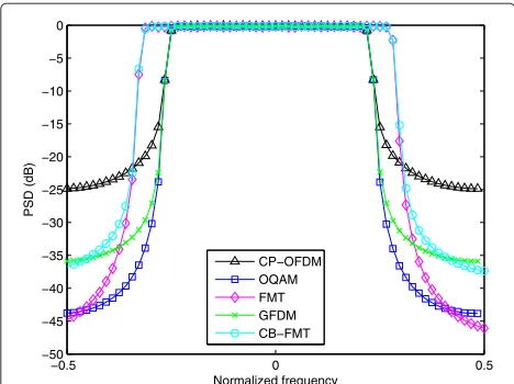
As stated in Section 1, the radio signal PSD may become even more important in future radio systems. Due to the spectrum scarcity, the physical layer modulation must provide an improved radio signal PSD for enabling envi-sioned DSA techniques. In fact, all the SoTA alternatives have claimed that they have better signal PSD than the CP-OFDM systems. In Figure 1, we show the estimated PSD corresponding to the SoTA schemes. Our estimation is based on Welch’s methodb[30]. To ensure a fair compar-ison, the same prototype filter, which is the SRRC filter,c is used for these schemes except for CP-OFDM. The comparison result clearly shows that all the alternative schemes to CP-OFDM provide enhanced PSD shape with greatly reduced out-of-band radiations. A further rela-tive comparison among them reveals that the OQAM and FMT schemes can outperform the others. This is because the OQAM and FMT are not block-transform-based pro-cessing. Therefore, there does not exist any spectral leak-age due to the waveform discontinuity [31]. However, such spectral leakage still exists for the GFDM and CB-FMT systems which are realized with the block transform pro-cessing, resulting in an increased out-of-band radiation. Moreover, it can be clearly seen from the estimated PSD that keeping the same number of active subcarriers for the FMT and CB-FMT leads to a larger effective bandwidth
−0.5 0 0.5
Figure 1Estimated PSD corresponding to the SoTA schemes.
PSD evaluation:M=64 andM/2 active carriers; CP lengthM/4 for CP-OFDM, GFDM, and CB-FMT; SRRC filter of roll-off factor 0.2 with overlapping factor 32 for OQAM, FMT, GFDM, and CB-FMT; N2=(5/4)Mfor FMT and CB-FMT;K=32 for GFDM and CB-FMT.
due to their increased subcarrier spacing. Thus, under a condition of keeping the same effective bandwidth, the FMT and CB-FMT must leave more carriers inactive.
2.2.3 Orthogonality analysis
The orthogonality is analyzed in two cases, i.e., end-to-end (E2E) distortion-free case and multi-path (MP) chan-nel case. The former shows whether the MCM can form a perfect reconstruction system. While the latter reveals the robustness against a frequency selective fading, mean-ing whether a simple one-tap equalizer can completely remove the multi-path interference, as such in the CP-OFDM case. It hints further on the complexity of the receiver design. This feature is particularly important for the case of CP-OFDM-based space-time encoded MISO transmission, since the space-time decoding can there-fore be simply realized by a one-tap equalization, result-ing in a low-complexity receiver. Nevertheless, there still remain open issues when combining space-time encoded MISO with some MCM schemes other than CP-OFDM. A well-known example is the possibility of enabling a low-complexity Alamouti transmission with advanced MCM schemes [16]. Thus, in general, more weights are given to the orthogonality than to the SE for the MCM evalua-tion. In the following, we assume that the inserted CP is always sufficiently longer than the MP channel length for CP-OFDM, GFDM, and CB-FMT. Note that the Doppler effect is not considered in our orthogonality analysis, as it ruins the orthogonality for all the MCM schemes in general. The robustness against Doppler effect will be investigated in future publications.
The CP-OFDM system is a well-known orthogonal sys-tem. It holds the perfect reconstruction in the E2E case. In a MP case, with the aid of CP, neither the ICI nor the inter-symbol interference (ISI) is resulted. Hence, the orthogonality is fully addressed in CP-OFDM systems. Thanks to this advantage, the CP-OFDM is recognized as a low-complexity system because the channel compen-sation can be easily accomplished with a simple one-tap equalizationd.
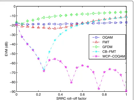
For the rest four MCM schemes, we use error vector magnitude (EVM) to evaluate their orthogonality perfor-mance. The EVM, sometimes also called constellation error magnitude, is defined as
EVM (dB)=10 log10
withcm,nthe transmitted data constellations andˆcm,nthe
simple two-path static channel with the second path of half channel gain of the first path.
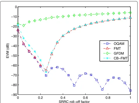
Again, the SRRC prototype filter is used for OQAM, FMT, GFDM, and CB-FMT. The detailed parameters are given in Figure 2, where the orthogonality performances are displayed as a function of the filter roll-off (RO) factor. This reflects the orthogonality influence with regard to different time-frequency localization weights of the pro-totype filter. Further, no background noise is assumed to illustrate a pure impact on the constellation error due to the non-orthogonality.
The evaluation result shows that the OQAM system is nearly orthogonal in the E2E case, since the curve remains under a low EVM value, except for small RO factors close to zero. This can be explained by the uncertainty principle ([28], Ch. 11), i.e., if a window is narrow in time domain, it is broad in frequency domain and vice versa. The SRRC pulse with small RO factor tends to a sinc pulse which holds the orthogonality only when the pulse duration goes to infinity. This also explains why the EVM of OQAM decreases as the RO factor increases. It is because the SRRC pulse with higher RO factor has better time domain localization. Thus, considering a SRRC pulse with a finite duration, it holds more tightly the perfect reconstruction. On the other hand, both the FMT and CB-FMT scheme have similar orthogonality performance in the E2E case. This is not a surprising result as they share the same mod-ulation kernel. Moreover, the result shows that they can maintain the orthogonality only if the RO factor does not exceed a certain threshold, whose value is calculated as
1+r= N2
M ⇒r=
N2−M
M . (10)
Beyond this threshold, the spectra of the adjacent sub-carriers start to reach across with each other, preventing
0 0.2 0.4 0.6 0.8 1
Figure 2EVM evaluation E2E case, SRRC filter with overlapping factor 32,M=64,N2=(5/4)M,K=32for GFDM and CB-FMT.
All carriers are modulated.
from the ICI-free assumption. Indeed, in line with [12], the wider the pulse spectrum is, the severer the ICI will be resulted. That is why the EVM curves for FMT and CB-FMT turn around at the threshold RO point and con-tinuously go up as the RO factor increases. The GFDM scheme provides the worst orthogonality performance in the E2E case due to its non-orthogonal nature.
Moving to the MP case, as shown in Figure 3, the orthogonality for the OQAM and FMT is severely ruined due to the lack of CP. This confirms their drawback that the OQAM and FMT can only hold the orthogonal sys-tem in the distortion-free case. Therefore, in practice, either multi-tap equalizers [32,33] or multi-step equal-izers [13,14] must be considered for OQAM and FMT [12,15] to mitigate the performance degradation. Similar to the E2E case, the GFDM continues badly performing due to its orthogonality loss. This degradation cannot be relieved with the aid of CP. For this reason, the GFDM receiver has to employ complex interference cancelation techniques, e.g., [34]. On the contrary, the CB-FMT keeps the same performance as in the E2E case. It reveals that the MP channel does not impact the orthogonality fea-ture of the CB-FMT, and it further points out that the only impacting factor for the orthogonality of CB-FMT is the time-frequency localization property of the prototype filter which brings to our next analysis item: waveform flexibility.
2.2.4 Waveform flexibility analysis
In this paper, the waveform flexibility is evaluated under two conditions: (1) the capability for MCM schemes to employ a non-rectangular filter without any penalty on orthogonality; (2) the capability for MCM schemes to employ a filter, which can be localized either in frequency
0 0.2 0.4 0.6 0.8 1
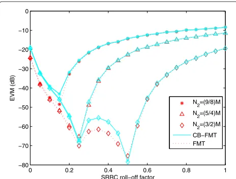
or in time domain, without any penalty. The evalua-tion on the first condievalua-tion is straightforward. But for the second condition, we analyze the orthogonality degra-dation by varying the RO factor of the filter, which reflects the penalty by employing the filters with differ-ent time-frequency localization combinations. The CP-OFDM uses a fixed rectangular pulse. Hence, it does not have any degree of flexibility. Unlike CP-OFDM, the OQAM scheme can use a prototype filter having either good time localization or good frequency localization or a good compromise. This is confirmed by Figure 2 that its perfect reconstruction is not significantly impacted as the RO factor changes. While for the FMT and CB-FMT, the orthogonality analysis reveals that well frequency-localized pulses are preferred. This remark is actually in line with the statement given in ([24], Sec.V.B). On the other hand, one could improve the waveform flexibility of FMT and CB-FMT by increasing the over-sampling fac-torN2. In line with (10), in Figure 4, it is shown that as
N2increases the RO factor threshold for which the FMT-based schemes can maintain orthogonality shifts to the right side. This indeed can be interpreted that more wave-form flexibility can be achieved for CB-FMT but at the price of more SE loss. Finally, the GFDM scheme is a spe-cial case. Since it cannot hold a perfect reconstruction condition, the waveform flexibility does not make much sense in this context.
3 COQAM: motivation and concept
As our analysis showed, the CP-OFDM cannot address any flexibility and its PSD has a high out-of-band radi-ation. The drawbacks of OQAM and FMT are lack of the orthogonality under multi-path channel, which requires more complicated receiver design and limits the
0 0.2 0.4 0.6 0.8 1
Figure 4EVM evaluation E2E case.SRRC filter of overlap factor 32, M=64,N2= {9/8, 5/4, 3/2}M,K=32 for CB-FMT.
feasibility with MIMO transmission. Even more severe orthogonality issue is inherited in the GFDM scheme, which further increases the system complexity and pre-vents waveform flexibility. The CB-FMT can completely solve the orthogonality issue under some constraints on the pulse design and it manages to improve the PSD shape compared with CP-OFDM. However, a compromise is laid among waveform flexibility, orthogonality, and SE loss. In addition, the CB-FMT inherits a two-dimensional SE loss.
Knowing the shortcomings, an intuitive question is whether we can find an improved modulation that keeps most of the benefits from the predecessors and gets rid of their drawbacks. With this motivation, we investigated a new MCM scheme called COQAM, whose idea is to replace the linear convolution used in the OQAM with a circular convolution, similar to the GFDM and CB-FMT. By this way, we get a modulation scheme that corre-sponds to a block transform. So that a CP can be easily added to enhance the orthogonality. Partly derived from (2), the discrete-time COQAM signal s[k] defined in a block interval such that k ∈[ 0,MK − 1] is expressed
withK the number of real symbol slots per each block. Note that the real symbols are obtained from taking the real and imaginary parts of QAM constellations. Thus, its relation to the symbol slotKintroduced in the GFDM sys-tem is thatK = 2K. This also implies that the COQAM and GFDM have a same block length, i.e.,KN1 = KM. The rest of the parameters are in line with those presented in the OQAM scheme. To implement a circular convolu-tion with a prototype filtergof lengthL=KM= D+1, we introduce a pulse shaping filter denotedg˜, obtained by the periodic repetition of durationKMof the prototype filterg, i.e.,g˜[k]=g[ mod(k,MK)].
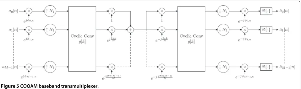
The COQAM is an orthogonal system and the orthog-onality condition for the filter design is analogous to (3), i.e., all the designed prototype filters for OQAM can be reused in COQAM systems. The corresponding baseband COQAM modulation structure is depicted in Figure 5.
4 Practical implementation schemes
Figure 5COQAM baseband transmultiplexer.
4.1 IFFT-based algorithm
Omitting some mathematical derivations, the baseband COQAM signal, for a block of sizeMK, can be expressed in a matrix form as
sCOQAMMK×1 =diagGMK×K
EMK×MWM×MAM×K
T
,
where (·)T denotes the matrix transpose operation and diag{·}corresponds to the extraction of the diagonal ele-ments of a matrix. AM×K is the matrix containing the
pre-processed data form∈[ 0,M−1] andn∈[ 0,K−1], i.e.,
AM×K =
am[n]ejφm,ne−
jπmD M
M×K.
The inverse Fourier transform matrix WM×M, with
input indices (m,k) ∈[ 0,M − 1], is expressed by {ej2πMmk}M×M. The extended matrixEMK×M corresponds
to aK repetition of the identity matrixIM×M of sizeM
given by
EMK×M =
IM×M . . . IM×M
T
. (12)
The polyphase circulant matrixGMK×Kreads as
GMK×K =
gk,n
MK×K,
withgk,n = g[ mod(k−nN1,MK)], fork ∈[ 0,MK−1] andn∈[ 0,K−1].
To get an efficient implementation scheme, the Fourier transform is carried out by a fast IFFT algorithm. Note also that the expansion operation does not require any arithmetic computation. Moreover, as the final operation boils down to the extraction of the diagonal elements, a full computation for matrix multiplications is not neces-sary. Thus, a large number of computations can be saved. To give a complete picture of our algorithm, we display in Figure 6, the modulation scheme for the processing of
one data block AM×K. It is worth noting that the gk,n
coefficients of the prototype filter, shifted for each slot of indexn, can be deduced from the expression of the proto-type filter considering different indexing. Therefore, once MandKare configured, the indexed coefficients can be pre-computed (off-line) and stored in look-up tables for n = 0. . .K−1. Furthermore, the expansion operation in Figure 6, given in (12), is used for our illustration pur-pose. In practice, there is no need to allocate extra buffers for copying data, one only needs to periodically reuse the same data.
4.2 Pruned IFFT-based algorithm
Our second proposal, which further reduces the transmit-ter complexity, takes advantage of a symmetry property of Fourier Transform. It turns out that only half of the Mcoefficients at the IFFT output need to be computed. Therefore, a pruned IFFT can be used instead of the con-ventionalM-point IFFT, resulting in a reduction of the computational complexity around 50%. A mathematical proof consists in a reformulation of (11) in which we specify the phase termφm,n= π2(m+n), i.e.,
Pruned IFFT + HSExt
, fork=0. . .M−1.
(15)
The complexity reduction operation involves a pruned IFFT and a Hermitian symmetric extension (HSExt), while a permutation (Permut) and a cyclic extension (CYCExt) are also needed afterwards. SettingD=L−1=MK−1, (15) is rewritten as
bk[n]=
Due to the fact thatam[n] are real-valued symbols, the
outputsbk[n] do not need to be obtained by a full size
IFFT but only a half size, given by
bk[n]=
Then the fullM-point outputs can be completed by the HSExt, i.e.,
bM−1−k[n]=bk∗[n] , fork=0. . .M/2−1.
Next, the Permut renders the right indexing to the out-puts, i.e.,
bk[n]=bmod(k−KM/2+M/4,M)[n] , fork=0. . .M−1.
Last, the CYCExt process completes the necessaryMK -point data for prototype filtering, fork = 0. . .MK−1, Assuming M is a power-of-2 integer, the traditional M-point IFFT, using the radix-2 Cooley-Tukey algo-rithm [35], requires (M/2)log2M complex multiplica-tions. Then, a pruned IFFT transform withMinputs and N1 outputs (N1 = M/2) yields a complexity reduction of at least 50% [36], i.e.,(M/4)log2M. Although it is not detailed in this paper, in practice, one could further imag-ine to design a filter with odd-value filter length, e.g., SRRC. With this change, it can be readily derived that the pre-processing in Figure 7 is completely avoided, leading the arithmetic complexity, for generating one COQAM block of sizeMK, to
# mult.=K(M/2)log2M
OFDM
+MK2. (16)
In (16), the former part reflects the number of multi-plications needed for OFDM modulation, processing the same amount of the data symbols. Thus,MK2represents the additional arithmetic complexity. In fact, the exact complexity calculation depends on the implementation algorithm. For example, the algorithm presented in this section is one of the possible ways to implement COQAM system. One may also consider using a frequency domain implementation concept which is introduced for GFDM and CB-FMT. Thus, the resulting complexity differs as a function of implementation algorithms. Moreover, the algorithm preference must be analyzed in the context of concrete system parameter setting, e.g., frame structure and concreteMandKvalues.
Figure 7Efficient implementation scheme of the COQAM modulator: pruned IFFT-based algorithm.
CP-COQAM (WCP-COQAM). Denoting the CP length byLCP, we get
LCP=LGI+LRI, (17)
whereLGIis the CP part used to fight against the multi-path channel interference andLRIis the portion devoted to windowing.
Thelth block of the WCP-COQAM signalsWCP-COQAM[k],
fork= 0. . .MK+LCP−1, can be obtained from thelth
block of the COQAM signal by
sWCP-COQAM[k] = l+1
r=l−1
sCOQAM[ mod(k−LCP,MK)]
×w[k−rQ] , (18)
where Q = MK + LGI and w[k], defined in the k =
0,. . .,MK + LCP − 1 interval, is the window function
computed as follows
w[k]= ⎧ ⎨ ⎩
window coeffs. k∈[ 0,LRI−1]
1 k∈[LRI,MK+LGI−1]
w[MK+LCP−1−k] otherwise.
There are extensive works on the window design [31]. In this paper, we simply use the triangle (Fejer, Bartlet) win-dow for this winwin-dowing process. Particular investigation on the window design in the context of COQAM will be envisaged in a future step. Furthermore, it is worth noting that the additional partLRIdoes not reduce the spectral efficiency since consecutive blocks are overlapped with the RI part, which means that the true redundancy for the transmission is the GI part. Moreover, it will be illustrated later that on the receiver side, for each block, only the first
GI samples are removed. The WCP-COQAM transmit-ter structure is depicted in Figure 8, wheres1[k] denotes
sCOQAM[k], which is obtained from (11) ands2[k] stands for
sWCP-COQAM[k].
Regarding the receiver structure, there are several dis-tinct algorithms for the WCP-COQAM demodulation. In this paper, we present one algorithm that is similar to the one presented for GFDM [17] and CB-FMT [24]. The structure is depicted in Figure 9 and a detailed illustration is given in the following. Assuming a perfect synchroniza-tion, the received WCP-COQAM signal is passed through a pre-processing phase, which takes away the CP and the windowing effect. This process consists in two steps. The received discrete signal is stored in a buffer of sizeL+LGI
samples (L = MK). Then, the firstLGIsamples are
omit-ted and followed by a cyclic shift operation, which can be written as
s[k]=s[ mod(k+LGI−1,MK)] , fork=0. . .MK−1.
Next, an L-point FFT operation is performed so that a frequency domain equalization (FDE) can be straightfor-wardly envisaged. Indeed, different equalization criteria can be chosen, e.g., minimum mean square error (MMSE) [24]. Here we stick to a simple one-tap ZF equalization. After, theLoutputs are multiplied by a shifted frequency domain prototype filter coefficient Gq,m, whose coeffi-cients are computed with an L-point Fourier transform of the prototype filterg[k] and shifted with regard to the subcarrier indexm, i.e., forq = 0. . .MK −1 andm = 0. . .M−1, we have
Figure 8Transmitter of the WCP-COQAM system.
with
G[q]=
MK−1
k=0
g[k]e−j2MKπkq. (19)
Afterwards, a folder operation is repeatedly performed for each of the M subcarriers which indeed realizes a subblock summation, i.e.,
ETMK×K =[IK×K. . .IK×K]T.
Note that a lot of computation savings can be envisioned here, because a large number of the coefficients ofG[q] are trivial values. Finally, a K-point IFFT is performed
for each subcarrier and the post-phase processing is given by
ψm,n= −
π
2(m+n)− πm
M (D−N1+2)
.
The detailed processing diagrams for the WCP-COQAM receiver structure are illustrated in Figure 9. The complex-ity analysis of the WCP-COQAM system will be discussed later in this paper.
6 Performance evaluation
Our research objective is to find an enhanced MCM scheme to maximally address the considered four aspects.
Therefore, we repeat the same analysis that has been reported in Section 2.2. This time, we take the WCP-COQAM into the comparison. In addition, the Bit Error Rate (BER) vs. Signal-to-Noise Ratio (SNR) comparison is also given for further illustrating the efficiency of the proposal in the presence of the background noise.
6.1 Spectral efficiency evaluation
First off, we analyze the SE of WCP-COQAM. As illus-trated in Section 5, for each WCP-COQAM block of size MK samples, a CP is inserted in the front of each block and is composed of two parts, i.e., LGI and LRI. How-ever, the latter part does not reduce the SE. Therefore, assuming that LGI has the same quantity as that used for the GFDM, the spectral efficiency indicator of the WCP-COQAM is same as that of the GFDM systems, i.e.,
SEIWCP-COQAM =
6.2 Power spectral density evaluation
In the respect of PSD evaluation, the SRRC filter is also used for the WCP-COQAM scheme. The bet-ter frequency-localized feature of SRRC pulse naturally makes the WCP-COQAM outperform the CP-OFDM, while the potential spectral leakage due to its block trans-form processing may augment the out-of-band radiation. This problem can be overcome with our proposed win-dowing process, and the estimated PSD in Figure 10 confirms this statement. Thus, the WCP-COQAM can maintain an excellent PSD shape. In addition, to effectively enable future DSA solutions, the signal PSD in fragmented
−0.5 0 0.5
Figure 10PSD evaluation of our proposed windowing process.
M=64 andM/2 active carriers; CP lengthM/4 for CP-OFDM, GFDM and CB-FMT; SRRC filter of roll-off factor 0.2 with overlapping factor 32 for OQAM, FMT, GFDM, CB-FMT, and WCP-COQAM;N2=(5/4)Mfor FMT and CB-FMT;K=32 for GFDM and CB-FMT;LGI=M/4 and LRI=6 for WCP-COQAM.
bands should also be evaluated because in future sys-tems, non-contiguous frequency band allocation will be an inevitable choice to drive the DSA to its ultimate limit. For this reason, Figure 11 shows the PSD comparison in the fragmented band case, where we switch off the same number of subcarriers located in the middle band for all these schemes. The result shows that the WCP-COQAM can still keep a satisfactorily low radiation level in the notch band.
6.3 Why is circular convolution necessary?
WCP-COQAM transforms the continuous-processing to the block-processing such that with the aid of CP, the one-tap frequency domain equalization can become effective. Nevertheless, one may wonder if the circular filtering is really necessary. For the classical OQAM scheme, it can also introduce a CP then applies the frequency domain equalization at the receiver. Such scheme is named CP-OQAM and it was proposed in [37]. In this section, we explain the necessity of using circular filtering instead of linear filtering and the difference between WCP-COQAM and CP-OQAM.
From the robustness against multi-path interference point of view, both schemes introduce CP and can ensure an interference-free transmission. Therefore, at this point, WCP-COQAM and CP-OQAM are quite equivalent. Nevertheless, for WCP-COQAM, there does not exist any waveform discontinuity within one block even when the CP is inserted. The only discontinuity appears between two consecutive blocks, which can be perfectly removed by the presented windowing process. On the other hand, for CP-OQAM, if a simple cutting is used to define blocks [37], the waveform is cut into two or several blocks depending on the prototype filter length and block length. In this case, the waveform discontinuity occurs within
−0.2 −0.1 0 0.1 0.2 0.3 0.4 0.5
the block especially when CP is appended in front of each block. Moreover, such discontinuity cannot be alle-viated by the windowing process, as they do not appear on the block edges. In Figure 12, we show the PSD com-parison between WCP-COQAM and CP-OQAM (w./wo. windowing) to prove the above statement. It is clearly shown that for CP-OQAM the discontinuity issue cannot be solved by the windowing process.
6.4 Orthogonality evaluation
The orthogonality evaluation for the WCP-COQAM is also done for E2E and MP cases. Same parameter setting as in Section 2.2.3 is used here. The EVM comparison in the E2E case is reported in Figure 13, where the WCP-COQAM curve is quite similar to the OQAM curve. This proves that the WCP-COQAM with SRRC filter can form a nearly perfect reconstruction system. Unlike OQAM, when we now move to the MP case, shown in Figure 14, the WCP-COQAM can still maintain the best orthog-onality, without being impaired by the time-frequency localization property of the prototype filter. This also indi-cates that the WCP-COQAM can indeed employ flexible waveforms without sacrificing this orthogonality feature.
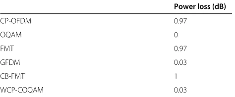
To provide a full picture of the orthogonality analysis, we further show the BER vs. SNR comparisons for all these MCM schemes. The constellation order is set to 16-QAM; we continue to use the simple two-tap channel as in Section 2.2.3. Figures 15,16,17 give the BER comparison results for different MCM schemes in three cases of SRRC filter with RO factor being 0.2, 0.5, and 0.8, respectively. The CP-OFDM performance is also included this time and it can be referred as a baseline in our comparison. Note that the SNR is considered by the total power spent on the transmitted symbols without taking into account the SE. The reason for this is to make the CP-OFDM an
−0.5 0 0.5
Figure 12PSD comparison WCP-COQAM vs. CP-OQAM vs. WCP-OQAM: same parameter setting as Figure 10.
0 0.2 0.4 0.6 0.8 1
Figure 13EVM evaluation, E2E case.SRRC filter with overlapping factor 32;M=64;K=32;N2=(5/4)Mfor GFDM and CB-FMT; LGI=M/4 andLRI=6 for WCP-COQAM.
accurate reference reflecting the interference-free perfor-mance. Nevertheless, in Table 1, the power loss due to CP insertion and subcarrier spacing increase (i.e., over-sampling) is given for each MCM scheme. The results show a good match between WCOQAM and CP-OFDM. The performance improvement, compared with OQAM, is clear and will be even more significant when the constellation order continues to increase. This proves that the drawback of OQAM is overcome by the WCP-COQAM scheme. Moreover, as the RO factor varies from 0.2 to 0.8, the BER curves of WCP-COQAM always matches with those of CP-OFDM. This further confirms
0 0.2 0.4 0.6 0.8 1
2 4 6 8 10 12 14 16 18 20 10−2
10−1
SNR (dB)
BER
CP−OFDM OQAM FMT GFDM CB−FMT WCP−COQAM
Figure 15BER vs. SNR evaluation: same parameter setting as Figure 14 and SRRC RO factor 0.2.
that the orthogonality feature of the WCP-COQAM sys-tem is not impacted by the waveform flexibility, which is the crucial factor for future mobile radio systems. On the other hand, when RO factor tends to a large value, in the BER performances of FMT and CB-FMT a severe degra-dation appears, which is in line with the EVM analysis. Finally, the GFDM results in the worse BER performance due to its non-orthogonality. Therefore, we can deduce that it probably is impossible to function a GFDM-based system with a one-tap equalization.
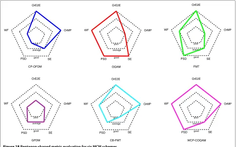
To give bird’s eye view on all of these MCM schemes evaluation, in Figure 18, we introduce a pentagon-shaped metric, whose five corners represent five evaluation crite-ria, i.e., SE, PSD, waveform flexibility (WF), orthogonality in E2E (OrE2E), and MP (OrMP) cases. Moreover, we use the inner/middle/outer layers to indicate three robustness
0 5 10 15 20
10−2 10−1
SNR (dB)
BER
CP−OFDM OQAM FMT GFDM CB−FMT WCP−COQAM
Figure 16BER vs. SNR evaluation: same parameter setting as Figure 14 and SRRC RO factor 0.5.
0 5 10 15 20
10−2 10−1
SNR (dB)
BER
CP−OFDM OQAM FMT GFDM CB−FMT WCP−COQAM
Figure 17BER vs. SNR evaluation: same parameter setting as Figure 14 and SRRC RO factor 0.8.
levels, i.e., poor/average/good. The corresponding curve of each MCM scheme reflects the final evaluation score, which gives the preference of the suitable scheme for future radio systems. Clearly, the WCP-COQAM mini-mizes the predecessors’ drawbacks while still keeping the maximum number of the advantages.
7 Discussions
7.1 WCP-COQAM receiver complexity
Similar to the transmitter side, the receiver complexity is also of paramount importance to be evaluated. Here, we provide a simple complexity analysis in terms of the number of arithmetical computations, i.e., complex mul-tiplications (CM). Then we provide a complexity and per-formance comparison of WCP-COQAM vs. the classical OQAM receiver employing non-trivial equalizers. This comparison reveals the interest of using WCP-COQAM scheme.
For WCP-COQAM receiver as shown in Figure 9, the arithmetical computation for processing one block of the received data (L = MK samples) can be divided into the computation of one FFT of size L, FDE for one block, polyphase filtering (product of FDE outputs and Gq,m), and IFFTs of size K forM subcarriers, noting that the
Table 1 Power loss due to CP and over-sampling
Power loss (dB)
CP-OFDM 0.97
OQAM 0
FMT 0.97
GFDM 0.03
CB-FMT 1
OrE2E
OrMP
PSD SE
WF
poor
average
good
OrE2E
OrMP
PSD SE
WF
poor
average
good
OrE2E
OrMP
PSD SE
WF
poor
average
good
OrE2E
OrMP
PSD SE
WF
poor
average
good
OrE2E
OrMP
PSD SE
WF
poor
average
good
OrE2E
OrMP
PSD SE
WF
poor
average
good
CP-OFDM OQAM FMT
GFDM CB-FMT WCP-COQAM
Figure 18Pentagon-shaped metric evaluation for six MCM schemes.
cyclic shift operation does not consume any arithmetical computations. Here we do not count the post-phase pro-cessing as it does not represent additional complexity with regard to the classical OQAM receiver. In more detail, theL-point FFT needs(L/2)log2LCMs. The FDE, which represents one-tap equalizer, yieldsLCMs. The product between FDE outputs andGq,mis a special case. AsGq,m represents the shifted version of the frequency coefficients of the prototype filter, it turns out that only a small por-tion of the frequency coefficients are non-zero-valued. If one uses the SRRC filter, the number of the non-zero coef-ficients can be analytically calculated. Assuming a SRRC prototype filter with RO factorr, its bandwidth thus yields
1+r
MTs (Hz), whereTsstands for the sample duration. From
(19) it shows that frequency resolution for calculating the frequency coefficients is 1/MKTs(Hz). Therefore, the number of non-zero coefficients can be obtained with the division between the bandwidth and the frequency resolution, i.e., (1+r)Kwith ·being the ceiling oper-ation. Thus, the polyphase filtering consumes M (1 + r)KCMs. At last, each of the K-point IFFT results in (K/2)log2K = Klog22K CMs which lead to a total of MKlog22KCMs.
Regarding the classical OQAM receiver for process-ing the same amount of data, we look at the two cases. The first uses a two-step equalizer named equalization
with interference cancelation (EIC) [13], and the second one applies a multi-tap equalizer (MTE) [32]. Assuming that the prototype filter is of lengthMK, the arithmetical computation needed for classical OQAM demodulation yieldsK timesM-point FFT (MKlog2MCMs), and the polyphase network (PPN) consumes MK2 CMs. In the case of EIC, the on-line arithmetical computatione [13] yields(8κ2+8κ+2)MKCMs whereκstands for the neigh-borhood zone within which the interference is considered for the interference canceler. In the case of multi-tap equalizer, the equalization yields 2ηMK CMs, where η represents the number of the taps. Table 2 summarizes the analyzed complexity for further comparison.
As explained in Section 2.2.2, the SRRC filter was cho-sen in our previous performance evaluation to ensure a fair comparison among different MCM schemes. How-ever, the drawback of SRRC filter comes from the necessity of using a long filter length which results in
Table 2 Receiver complexity analysis
Schemes Number of complex multiplications
WCP-COQAM MKlog2MK
2 +log22K+1
a high receiver complexity. In practice, for the WCP-COQAM and classical OQAM schemes, the orthogonal-ity condition (3) can be perfectly held with a moder-ate filter length, e.g., overlapping factor ≤ 4. In what follows, we show the performance comparison among WCP-COQAM, OQAM-EIC, and OQAM-MTE.
In this simulation, the prototype filter is now changed to a OQAM-dedicated filter namedfrequency selective(FS) [27] with overlapping factor of 4. This corresponds for WCP-COQAM to K = 4. For OQAM-EIC, the neigh-borhood zone is set to 1, indicating that only the interfer-ence coming from the closest neighbors is canceled. For OQAM-MTE, a three-tap equalizer is considered. More-over, we increase the channel delay spread up toM/6 in order to clearly show the performance degradation due to the multi-path interference. The rest of the parameters are in line with those reported in Section 6. The performance is reported in Figure 19 and the corresponding power loss and the complexity are given in Tables 3 and 4, respec-tively. Note that our FS filter is designed to have similar bandwidth to SRRC with RO factor 1. The results confirm that the WCP-COQAM can address a better performance with less complexity.
7.2 How can WCP-COQAM combine with Alamouti? As discussed in the previous section, the WCP-COQAM has similar robustness of the multi-path interference immunity as for the CP-OQAM scheme. Therefore, the solutions proposed for CP-OQAM scheme can be eas-ily tailored to WCP-COQAM system. Among them, one solution called pseudo-Alamouti encoding was pro-posed to CP-OQAM [38] which allows for a simple low-complexity decoding algorithm on the receiver side. To extend this scheme for WCP-COQAM, the encoding process can remain the same as [38], while the receiver
0 5 10 15 20 25 30
10−2 10−1
SNR (dB)
BER
OQAM−EIC OQAM−MTE OQAM−ZF WCP−COQAM
Figure 19BER vs. SNR evaluation: WCP-COQAM vs. OQAM-EIC vs. OQAM-MTE.
Table 3 Power loss due to CP
WCP-COQAM OQAM-ZF OQAM-EIC OQAM-MTE
Power loss 0.26 dB 0 dB 0 dB 0 dB
structure should be modified according to Figure 9. The details of the WCP-COQAM-based Alamouti transmis-sion will be given in our future publication. Moreover, in the literature, there are proposals on the Alamouti-FBMC/OQAM, e.g., [39,40]. In [39], a block-wise Alam-outi encoding is proposed, where the notion of block is defined by inserting zero-symbols, leading to a compro-mise between the spectral efficiency and receiver memory buffer. In [40], an FFT-FBMC scheme, together with a spe-cial data transmission strategy has been proposed. This scheme can be seen as a subcarrier-wise precoded FBMC system. The ISI at each subcarrier can be easily removed by a simple equalization, thanks to the subcarrier-wise IFFT precoding and CP insertion, while the ICI level can be controlled by a special data transmission strat-egy and good frequency-localized prototype filter. It is claimed that this scheme can well enable the Alamouti transmission with a reasonable added complexity. The performance evaluation as well as the complexity compar-ison among these schemes for Alamouti transmission will be envisioned in our future work.
7.3 WCP-COQAM receiver flexibility
It is worth pointing out that there are potential degrees of flexibility that can be explored on the WCP-COQAM receiver side. In fact, as stated in Section 5, the presented receiver structure in Figure 9 illustrates one possible way of receiver processing. Otherwise said, it can be consid-ered as one receiver mode. Alternative receiver modes can be envisioned, for instance, we can imagine to estab-lish a receiver structure which realizes a dual process to Figure 6, as shown in Figure 20, where this mode performs the equalization after the filter bank. Moreover, the SoTA equalization methods for classical OQAM can be readily adapted to this mode which could be more beneficial in some particular transmission contexts, e.g., high Doppler spread. The most interesting feature is that this receiver flexibility leaves the receiver to decide which mode to be activated without any transmitted signal modifications. It indeed inspires future research investigations on how to efficiently take advantage of this flexibility.
Table 4 Complexity comparison in a specific context Schemes Number of complex multiplications
WCP-COQAM 2,560
OQAM-EIC 7,168
Figure 20WCP-COQAM alternative receiver mode.
7.4 Differentiation of WCP-COQAM and Abdoli et al. In the end, we would like to spend some space to dis-cuss the commonality and the difference between our contributions and that of in [41]. First off, [41] has a different motivation that aims at the reduction of the overhead of the OQAM system in a burst transmission, which ends up with a similar concept that uses a circu-lar convolution filtering instead of the linear convolution, and a time-windowing is also proposed to improve the PSD. Nevertheless, the differences between the proposal of [41] and ours are that our proposal is based on a reg-ular circreg-ular convolution, while in [41] it is claimed that the regular circular convolution is avoided and instead, a weighted circular convolution version is used. Second, the system realization is totally different and the window-ing process is also different. Moreover, the orthogonality enhancement in a multi-path channel context is not in the investigation scope of [41]. Finally, comparing the classical OQAM scheme, with the same SRRC prototype filter the proposal in ([41], Tab. I), leads to an orthogonality loss, while this is not the case in our proposal.
8 Conclusions
In this paper, we analyzed five SoTA MCM schemes from different aspects which are deemed as the important fac-tors for future radio systems. The analyzed results showed that none of the SoTA schemes can simultaneously
address these aspects. Then, we proposed a novel MCM scheme, which is a combination version of the classical OQAM with the circular convolution concept. Its con-cept and efficient implementation as well as its transceiver algorithm were reported. Finally, the efficiency of the pro-posed scheme was analyzed in terms of the evaluation criteria, and it turned out that our proposed scheme can indeed address these aspects to a maximum degree. Nev-ertheless, the selected evaluative criteria do not cover all of the research aspects that naturally triggers further investigations. To continue the work, our future research will cover the performance and complexity analysis for Alamouti-encoded transmission, in which different pro-posals in the literature will be compared together. More-over, the sensitivity of WCP-COQAM to the synchroniza-tion error will also be addressed. Furthermore, effort will also be made to address the remaining issues such as how to adapt the pilot structure to the WCP-COQAM system and how to take advantage of the WCP-COQAM receiver flexibility.
Endnotes
aDuring the paper preparation, we spotted that a
bIn this paper, the PSD is simulated with Welch’s
method, where the segment length is set toMfor CP-OFDM, OQAM, and GFDM andN2for FMT and CB-FMT. The initial shift between segments is taken equal to half of the segment length.
cIn the literature, the only reported filter for the GFDM
and CB-FMT systems is the SRRC. Therefore, in this paper, we stick to the SRRC to ensure the filter alignment, even though it is not the most favorable choice for the OQAM and FMT schemes as it cannot exactly hold an orthogonal condition with a finite length.
dA condition for this statement is that the CP-OFDM
symbol duration is smaller than the channel coherence time.
eOn-line arithmetical computation means the
calculation needed for each received sample. Its counterpart is the periodic mathematical computation, meaning that the calculation is only needed punctually.
Competing interests
The authors declare that they have no competing interests.
Acknowledgements
This work has been performed in the framework of the FP7 project ICT-317669 METIS. The authors would like to acknowledge the contributions of their colleagues.
Received: 22 November 2013 Accepted: 6 May 2014 Published: 30 May 2014
References
1. METIS deliverable D6.2, Initial report on horizontal topics, results and system concept. Technical Report ICT-317669 (March 2014)
2. METIS deliverable D1.1, Scenarios, requirements and KPIs for 5G mobile and wireless system. Technical Report ICT-317669 (May 2013) 3. G Matz, H Bölcskei, F Hlawatsch, Time-frequency foundations of
communications. IEEE Signal Process. Mag.30(6), 87–969 (2013) 4. H Saeedi-Sourck, Y Wu, JWM Bergmans, S Sadri, B Farhang-Boroujeny,
Sensitivity analysis of offset QAM multicarrier systems to residual carrier frequency and timing offsets. Signal Process.91(7), 1604–1612 (2011) 5. H Lin, M Gharba, P Siohan, Impact of time and carrier frequency offsets on
the FBMC/OQAM modulation scheme. Signal Process.102, 151–162 (2014)
6. JJ Benedetto, C Heil, DF Walnut, Differentiation and the Balian-Low theorem. J. Fourier Anal. Appl.1(4), 355–402 (1995)
7. BR Saltzberg, Performance of an efficient parallel data transmission system. IEEE Trans. Commun. Technol.15(6), 805–811 (1967) 8. SB Weinstein, PM Ebert, Data transmission by frequency-division
multiplexing using the discrete Fourier transform. IEEE Trans. Commun. 19, 628–634 (1971)
9. R Vallet, K Haj Taieb, Fraction spaced multi-carrier modulation transmission. Wireless Pers. Commun.2, 97–103 (1995) 10. R Hleiss, P Duhamel, M Charbit, Oversampled OFDM systems, in
Proceedings International Conference on Digital Signal Processing(Santorini,
Greece, July 1997)
11. C Siclet, P Siohan, D Pinchon, Perfect reconstruction conditions and design of oversampled DFT modulated transmultiplexers. Eurasip J. Appl. Signal Process, 14 pages (2006). Article ID 15756
12. G Cherubini, E Eleftheriou, S Ölçer, Filtered multitone modulation for very high-speed subscriber lines. IEEE J. Selected Areas Commun.
20(5), 1016–1028 (2002)
13. H Lin, P Siohan, P Tanguy, JP Javaudin, An analysis of EIC for OFDM/OQAM systems. J. Commun.4(1), 52–60 (2008)
14. G Ndo, H Lin, P Siohan, FBMC/OQAM equalization: exploiting the imaginary interference, inPIMRC’12(Sydney, Australia, September 2012) 15. N Benvenuto, S Tomasin, L Tomba, Equalization methods in OFDM and
FMT systems for broadband wireless communications. IEEE Trans. Commun.50(9), 1413–1418 (2002)
16. R Zakaria, D Le Ruyet, On interference cancellation in Alamouti coding scheme for filter bank based multicarrier systems, inISWCS(Ilmenau, Germany, June 2013)
17. G Fettweis, M Krondorf, S Bittner, GFDM-generalized frequency division multiplexing, inIEEE Vehicular Technology Conference (VTC Spring’09) (Barcelona, Spain, April 2009)
18. N Michailow, M Lentmaier, P Rost, G Fettweis, Integration of a GFDM secondary system in an OFDM primary system, inFuture Network and
Mobile Summit (FNMS’11)(Warsaw, January 2011)
19. R Datta, N Michailow, S Krone, M Lentmaier, G Fettweis, Generalized frequency division multiplexing in cognitive radio, inEuropean Signal
Processing Conference (EUSIPCO’12)(Bucharest, Romania,
August 2012)
20. R Datta, N Michailow, M Lentmaier, G Fettweis, GFDM interference cancellation for flexible cognitive radio PHY design, inIEEE Vehicular
Technology Conference (VTC Fall’12)(Quebec, Canada, September 2012)
21. R Datta, D Panaitopol, G Fettweis, Analysis of cyclostationary GFDM signal properties in flexible cognitive radio, inInternational Symposium on
Communication and Information Technologies (ISCIT’12)(Gold Coast,
Australia, October 2012)
22. N Michailow, I Gaspar, S Krone, M Lentmaier, G Fettweis, Generalized frequency division multiplexing: analysis of an alternative multi-carrier technique for next generation cellular systems, inInternational Symposium
on Wireless Communiation System (ISWCS’12)(Paris, France, August 2012)
23. N Michailow, S Krone, M Lentmaier, G Fettweis, Bit error rate performance of generalized frequency division multiplexing, inIEEE Vehicular
Technology Conference (VTC Fall’12)(Quebec, Canada,
September 2012)
24. AM Tonello, A novel multi-carrier scheme: cyclic block filtered multitone modulation, inProceedings of ICC 2013(Budapest, June 2013)
25. HG Feichtinger, T Strohmer,Gabor Analysis and Algorithm - Theory and Applications, (Birkhäuser, Boston-Basel-Berlin, 1998)
26. B Le Floch, M Alard, C Berrou, Coded orthogonal frequency division multiplex. Proc. IEEE.83, 982–996 (1995)
27. P Siohan, C Siclet, N Lacaille, Analysis and design of OFDM/OQAM systems based on filterbank theory. IEEE Trans. Signal Process. 50(5), 1170–1183 (2002)
28. PP Vaidyanathan,Multirate Systems and Filter Banks. (Prentice Hall, Englewood Cliffs, New York, New Jersey, 1993)
29. WY Zou, Y Wu, COFDM: an overview. IEEE Trans. Broadcast. 41(1), 1–8 (1995)
30. PD Welch, The use of fast Fourier transform for the estimation of power spectra: a method based on time averaging over short, modified periodograms. IEEE Trans. Audio Electroacoust.AU-15, 17–20 (1967) 31. FJ Harris, On the use of windows for harmonic analysis with the discrete
Fourier transform. Proc. IEEE.66(1), 51–83 (1978)
32. T Ihalainen, TH Stitz, M Rinne, M Renfors, Channel equalization in filter bank based multicarrier modulation for wireless communications. EURASIP J. Adv. Signal Process.2007(ID 49389), 1–18 (2007) 33. T Ihalainen, A Ikhlef, J Louveaux, M Renfors, Channel equalization for
multi-antenna FBMC/OQAM receivers. IEEE Trans. Vehic. Technol. 60(5), 2070–2085 (2011)
34. N Michailow, R Datta, S Krone, M Lentmaier, G Fettweis, Generalized frequency division multiplexing: a flexible multi-carrier modulation scheme for 5th generation cellular networks, inProceedings of the German
Microwave Conference (GeMiC’12)(Ilmenau, Germany, March 2012)
35. JW Cooley, JW Tukey, An algorithm for machine computation of complex Fourier series. Math. Comput.19(90), 297–301 (1965)
36. Y Dandach, P Siohan, FBMC/OQAM modulators with half complexity, in
Proceedings Globecom’11(Houston, December 2011)
37. H Lin, P Siohan, A new transceiver design for OFDM/OQAM modulation with cyclic prefix, inPIMRC’08(Cannes, France, September 2008) 38. H Lin, Lélé C, P Siohan, A pseudo Alamouti transceiver design for
39. M Renfors, T Ihalainen, TH Stitz, A block-Alamouti scheme for filter bank based multicarrier transmission, inProceedings of the 2010 European
Wireless Conference(Lucca, April 2010), pp. 1038–1041
40. R Zakaria, D Le Ruyet, A novel filter-bank multicarrier scheme to mitigate the intrinsic interference: application to MIMO systems. IEEE Trans. Wireless Commun.11(3), 1112–1123 (2012)
41. MJ Abdoli, M Jia, J Ma, Weighted circularly convolved filtering in OFDM/OQAM, inPIMRC’13(London, September 2013), pp. 8–11
doi:10.1186/1687-6180-2014-79
Cite this article as:Lin and Siohan:Multi-carrier modulation analysis and WCP-COQAM proposal.EURASIP Journal on Advances in Signal Processing
20142014:79.
Submit your manuscript to a
journal and benefi t from:
7Convenient online submission 7Rigorous peer review
7Immediate publication on acceptance 7Open access: articles freely available online 7High visibility within the fi eld
7Retaining the copyright to your article