A Review on Power Quality Problems and their Solutions
1
Fatehbir Singh &
2Preetmani Singh
1
Assistant Professor GJGI Patiala,India [email protected]
2
Senior LecturerGIMET Amritsar,India [email protected]
Abstract—
Power quality is one of major problems in the today’s scenario. It has become important with the introduction of complex devices, whose performance is very sensitive to the quality of power supply. Power quality problem is an occurrence developed as a nonstandard voltage, current or frequency that results in a failure of end use equipments. Some of the major problems dealt here is the power sag and swell. This paper describes the effectiveness of using dynamic voltage restorer (DVR) in order to mitigate voltage sags and swells in low voltage distribution systems. Dynamic Voltage Restorer can provide the most cost effective solution to mitigate voltage sags and swells that is required by customer. The Dynamic Voltage Restorer (DVR) is a rapid, flexible and resourceful solution to power quality problems
Keywords: - DVR (Dynamic Voltage Restorer); Harmonic Elimination; Power Quality; Voltage Sag; Voltage Swell
I. INTRODUCTION Power Quality (PQ) related issues are of most concern now days. The widespread use of electronic equipment, such as
information technology equipment, power electronics such as adjustable speed drives (ASD), programmable logic controllers(PLC), energy-efficient lighting etc led to a complete change of electric loads nature. These loads are simultaneously the major causers and the major victims of power quality problems [1]. Due to their non-linearity, all these loads cause disturbances in the voltage waveform. Along with technology advance, the organization of the worldwide economy has evolved towards globalization and the profit margins of many activities tend to decrease. The increased sensitivity of the vast majority of processes (industrial, services and even residential) to PQ problems turns the availability of electric power with quality a crucial factor for competitiveness in every activity sector. The most critical areas are the continuous process industry and the information technology services [2].
II. POWER QUALITY
Power is simply the flow of energy and the current demanded by a load is largely uncontrollable. “Power quality” is a convenient term for many; it is the quality of the voltage, rather than power or electric current. The term is used to describe electric power that drives an electrical load and the load's ability to function properly. The performance of electronic devices is directly linked to the power quality level in a facility. The electric power industry comprises electricity
generation (AC power), electric power transmission and ultimately electricity distribution to an electricity meter located at the premises of the end user of the electric power. The electricity then moves through the wiring system of the end user until it reaches the load. The complexity of the system to move electric energy from the point of production to the point of consumption combined with variations in weather, generation, demand and other factors provide many opportunities for the quality of supply to be compromised [3].
III. IMPACTS OF POWER QUALITY PROBLEMS There are many ways in which electric power can be of poor quality and many more causes of such poor quality power. Some of the most common power supply problems and their likely effect are :
1. Voltage surges/spikes
Voltage surges/spikes are the opposite of dips – a rise that may be nearly instantaneous (spike) or takes place over a longer duration (surge). A voltage surge takes place when the voltage is 110% or more above normal. The most common cause is heavy electrical equipment being turned off. Under these conditions, computer systems and other high tech equipment can experience flickering lights, equipment shutoff, errors or memory loss. Possible Solutions are surge suppressors, voltage regulators, uninterruptable power supplies, power conditioners[4].
Short duration under-voltages are called “Voltage Sags” or “Voltage Dips [IEC]”. Voltage sag [5, 6] is a reduction in the supply voltage magnitude followed by a voltage recovery after a short period of time. The major cause of voltage dips on a supply system is a fault on the system, i.e. sufficiently remote electrically that a voltage interruption does not occur. Other sources are the starting of large loads and, occasionally, the supply of large inductive loads [6]. The impact on consumers may range from the annoying (non-periodic light flicker) to the serious (tripping of sensitive loads and stalling of motors.
3. Under voltages
Excessive network loading, loss of generation, incorrectly set transformer taps and voltage regulator malfunctions, causes under voltage. Loads with a poor power factor or a general lack of reactive power support on a network also contribute. Under voltage can also indirectly lead to overloading problems as equipment takes an increased current to maintain power output (e.g. motor loads) [5].
4. High-Voltage Spikes
High-voltage spikes occur when there is a sudden voltage peak of up to 6,000 volts. These spikes are usually the result of nearby lightning strikes, but there can be other causes as well. The effects on vulnerable electronic systems can include loss of data and burned circuit boards. Possible Solutions are using Surge Suppressors, Voltage Regulators, Uninterruptable Power Supplies, Power Conditioners [7].
5. Frequency Variation
A frequency variation involves a change in frequency from the normally stable utility frequency of 50 or 60 Hz, depending on your geographic location. This may be caused by erratic operation of emergency generators or unstable frequency power sources. For sensitive equipment, the results can be data loss, program failure, equipment lock-up or complete shutdown. Possible Solutions are using Voltage Regulators and Power Conditioners [7].
6. Power Sag
Power sags are a common power quality problem. Despite being a short duration (10ms to 1s) event during which a reduction in the RMS voltage magnitude takes place, a small reduction in the system voltage can cause serious consequences. Sages are usually caused by system faults, and often the result of switching on loads with high demand startup currents. For more details about power sags visit our newsletter archives. Possible
Solutions are using Voltage Regulators, Uninterruptable Power Supplies, and Power Conditioners [8].
7. Blackouts
A power failure or blackout is a zero-voltage condition that lasts for more than two cycles. It may be caused by tripping a circuit breaker, power distribution failure or utility power failure. A blackout can cause data loss or corruption and equipment damage. Possible Solutions is using Generators[9].
8. Very short interruptions
Total interruption of electrical supply for duration from few milliseconds to one or two seconds. Mainly due to the opening and automatic reclosure of protection devices to decommission a faulty section of the network. The main fault causes are insulation failure, lightning and insulator flashover. Consequences of these interruptions are tripping of protection devices, loss of information and malfunction of data processing equipment [10].
9. Long interruptions
Long interruption of electrical supply for duration greater than 1 to 2 seconds. The main fault causes are Equipment failure in the power system network, storms and objects (trees, cars, etc) striking lines or poles, fire, human error, bad coordination or failure of protection devices. A consequence of these interruptions is stoppage of all equipment [1].
10. Voltage swell
Momentary increase of the voltage, at the power frequency, outside the normal tolerances, with duration of more than one cycle and typically less than a few seconds. The main causes are Start/stop of heavy loads, badly dimensioned power sources, badly regulated transformers (mainly during off-peak hours).Consequences is data loss, flickering of lighting and screens, stoppage or damage of sensitive equipment, if the voltage values are too high [10].
11. Harmonic distortion
electronics equipment including ASDs, switched mode power supplies, data processing equipment, high efficiency lighting [10].
IV. POWER QUALITY SOLUTION
Besides energy storage systems and DG, some other devices may be used to solve PQ problems. Using proper interface devices, one can isolate the loads from disturbances deriving from the grid.
A.Power Conditioning Equipments
Several types of power enhancement devices have been developed over the years to protect equipment from power disturbances. The following devices play a crucial role in developing an effective power quality strategy.
1. Transient Voltage Surge Suppressors (TVSS)
It provides the simplest and least expensive way to condition power. These units clamp transient impulses (spikes) to a level that is safe for the electronic load. TVSSs usually contain a component with a nonlinear resistance (a metal oxide varistor or a zener diode) that limits excessive line voltage and conduct any excess impulse energy to ground [11].
2. Voltage Regulators
Voltage regulators maintain output voltage at nominal voltage under all but the most severe input voltage variations. Voltage regulators are normally installed where the input voltage fluctuates, but total loss of power is uncommon. There are three basic types of regulators:
Tap Changers: Designed to adjust for varying input voltages by automatically transferring taps on a power transformer. The main advantage of tap changes over other voltage regulation technology is high efficiency
Constant Voltage Transformer (CVT): Also known as ferroresonant transformers. The CVT is a completely static regulator that maintains a nearly constant voltage during large variations in input voltage[11].
3. Dynamic Voltage Restorer
A dynamic voltage restorer (DVR) acts like a voltage source connected in series with the load. The output voltage of the DVR is kept approximately constant voltage at the load terminals by using a step-up transformer and/or stored energy to inject active and reactive power in the output supply trough a voltage converter [12].
B. Energy Storage Systems
Energy storage systems, also known as restoring technologies, are used to provide the electric loads with ride-through capability in poor PQ environment. Storage systems can be used to protect sensitive production equipment from shutdowns caused by voltage sags or momentary interruptions. These are usually dc storage systems, such as UPS, batteries, superconducting magnet energy storage (SMES) [13], storage capacitors etc. The output of these devices is supplied to the system through an inverter on a momentary basis by a fast acting electronic switch. Enough energy is fed to the system to replace the energy that would be lost by the voltage sag or interruption.
1. Flywheels
A flywheel is an electromechanical device that couples a rotating electric machine (motor/generator) with a rotating mass to store energy for short durations. The motor/generator draws power provided by the grid to keep the rotor of the flywheel spinning. During a power disturbance, the kinetic energy stored in the rotor is transformed to DC electric energy by the generator, and the energy is delivered at a constant frequency and voltage through an inverter and a control system[13].
2. Supercapacitors
Supercapacitors (also known as ultracapacitors) are DC energy sources and must be interfaced to the electric grid with a static power conditioner, providing energy output at the grid frequency. A supercapacitor provides power during short duration interruptions or voltage sags. Medium size supercapacitors (1 MJoule) are commercially available to implement ride-through capability in small electronic equipment, but large supercapacitors are still in development[12].
3. Superconducting Magnetic Energy Storage
(SMES)
A magnetic field is created by circulating a DC current in a closed coil of superconducting wire. The path of the coil circulating current can be opened with a solid-state switch, which is modulated on and off. Due to the high inductance of the coil, when the switch is off (open), the magnetic coil behaves as a current source and will force current into the power converter which will charge to some voltage level[12].
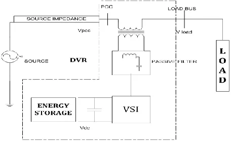
Dynamic voltage restorer (DVR) can provide the lucrative solution to mitigate voltage sag by establishing the appropriate voltage quality level, necessary. It is recently being used as the active solution for mitigation of power quality problems. Fig. I. shows basic structure of a DVR
Fig. I. Basic Structure of A DVR
The basic parts of a DVR are as under. (i) Energy Storage Unit:
This unit is responsible for energy storage in DC form. Flywheels, Batteries, superconducting magnetic energy storage (SMES) and super capacitors can be used as energy storage devices. It is supplies the real power requirements of the system when DVR is used for compensation.
(ii) Capacitor:
DVR has a large DC capacitor to ensure a proper DC voltage input to Inverter.
(iii) Inverter:
Inverter system is used to convert dc storage into ac. Voltage source inverter (VSI) of low voltage and high current with step up injection transformer is used for this purpose in the DVR Compensation technique. (iv) Passive Filters:
Filters convert the inverted PWM waveform into a sinusoidal waveform easily. This is achieved by eliminating the unwanted harmonic components generated VSI action. Higher orders harmonic components distort the compensated output voltage. (v) By-Pass Switch:
It is used to protect the inverter from high current in the presence of unwanted conditions. During the occurrence of a fault or a short circuit, DVR changes it into the bypass condition where the VSI inverter is protected against over current flowing through the power semiconductor switches. The rating of the DVR inverters is a limiting factor for normal load current
seen in the primary winding and reflected to the secondary winding of the series insertion transformer. (vi) Voltage Injection Transformers:
In a three-phase system, either three single-phase transformer units or one three phase transformer unit can be used for voltage injection purpose [15].
Basic principal of DVR is to transfer the voltage sag compensation value from DC side of the inverter to the injected transformer after filter. The compensation capacity of a particular DVR depends on the maximum voltage injection capability and the active power that can be supplied by the DVR. When DVR’s voltage disturbance occurs, active power or energy should be injected from DVR to the distribution system A DC system, which is connected to the inverter input, contains a large capacitor for storage energy. It provides reactive power to the load during faulty conditions. When the energy is drawn from the energy storage capacitors, the capacitor terminal voltage decrease. Therefore, there is a minimum voltage required below which the inverter of the DVR cannot generate the require voltage thus, size and rating of capacitor is very important for DVR power circuit[14].
VI DVR OPERATING STATES
1. During a voltage sag/swell on the line: The DVR injects the difference between the pre-sag and the sag voltage, by supplying the real power requirement from the energy storage device together with the reactive power. The maximum injection capability of the DVR is limited by the ratings of the DC energy storage and the voltage injection transformer ratio. In the case of three single-phase DVRs the magnitude of the injected voltage can be controlled individually. The injected voltages are made synchronized (i.e. same frequency and the phase angle) with the network voltages.
2. During the normal operation: As the network is working under normal condition the DVR is not injecting any voltages to the system. In that case, if the energy storage device is fully charged then the DVR operates in the standby mode or otherwise it operates in the self-charging mode. The energy storage device can be charged either from the power supply itself or from a different source.
flow of high fault current through it, which can damage the sensitive power electronic components[15].
Fig II. Simple Power System Using a DVR
During the voltage sag, magnitude and the phase angle of the supply voltage can be altered and it is denoted by Vsag. The DVR is in functioning state in this case and the voltage injected will be VDVR. If the voltage sag is fully compensated by the DVR, the load voltage during the voltage sag will be Vpre-sag.
A) Pre-sag compensation:
This compensation approach is suggested for the non-linear loads (e.g.: thyristor controlled drives) which requires both the voltage magnitude as well as the phase angle to be compensated. In this technique the DVR supplies the difference between the pre-sag and the sag voltage, thus restore the voltage magnitude and the phase angle to that of the pre-sag value. Figure IV below describes the pre-sag compensation technique. However this technique needs a higher rated energy storage device and voltage injection transformers.
Fig. III. Pre Sag Compensation
B) In-phase compensation:
The DVR compensates only for the voltage magnitude in this particular compensation method, i.e. the compensated voltage is in-phase with the sagged
voltage and only compensating for the voltage magnitude. Therefore this technique minimizes the voltage injected by the DVR. Hence it is recommended for the linear loads, which need not to be compensated for the phase angle. This particular compensation technique is shown in Figure V. It is clear from the Figure V. that there is a phase shift between the voltages before the sag and after the sag.
Fig IV. In Phase Compensation
C) Energy optimization technique
In this particular control technique the use of real power is minimized (or made equal to zero) by injecting the required voltage by the DVR at a 90° phase angle to the load current. Figure VI depicts the energy optimization technique. However in this technique the injected voltage will become higher than that of the in-phase compensation technique[14].
Fig V. Energy Optimization Technique
VIII. REFERENCES
[1] Delgado, J., “Gestão da Qualidade Total Aplicada ao Sector do Fornecimento da Energia Eléctrica”, Thesis submitted to fulfilment of the requirements for the degree of PhD. In Electrotechnical Engineering, Coimbra, September 2002.
[2] Ferracci, P., “Power Quality”, Schneider Electric Cahier Technique no. 199, September 2000.
[3] Ribeiro, P. , Johnson, B., Crow, M., Arsoy, A., Liu, Y., “Energy
Storage Systems for Advanced Power Applications”, Proceedings of the IEEE, vol. 89, pp.12, 2001.
[4] http://www.learnemc.com/tutorials/Transient_Protection/t-protect.html.
[5] Styvaktakis, M., Bollen, H.J. , Gu, I.Y.H. , “Classification of power system events: Voltage dips,” 9th International IEEE Conference on Harmonics and Quality of Power, Orlando, Florida USA, Vol. 2, pp. 745- 750, 2000.
[7] http://www.power-solutions.com/power-quality.
[8] Shailesh M. Deshmukh1, Bharti Dewani, S. P. Gawande, A review of Power Quality Problems-Voltage Sags for Different Faults,International Journal of Scientific Engineering and Technology, Volume No.2, Issue No.5, pp. 392-3971, 2013. [9]
Steven Warren Blume, Electric power system basics: for the nonelectrical professional. John Wiley & Sons, pp. 199, 2007. [10]
[10] Bollen, M. , “Understanding Power Quality Problems – Voltage Sags and Interruptions”, IEEE Press Series on Power Engineering – John Wiley and Sons, Piscataway, USA (2000).
[11] Marty Martin, “Common power quality problems and best practice solutions,” Shangri-la Kuala Lumpur, Malaysia 14. 1997.
[12] Sabin D.D., Sundaram, A.,“Quality enhances reliability”. IEEE Spectrum, Feb. 1996. 34-41.
[13] Kim, H.J. , Seong, K.C., Cho, J.W., Bae, J.H., Sim, K.D. , Kim, S., Lee, E.Y., Ryu K., Kim, S.H. , “3 MJ/750 kVA SMES System for Improving Power Quality,” IEEE Trans. on Superconductivity, Vol. 16(2), pp. 574- 577, 2006.
[14] A.K. Damor, Prof. V. B. Babaria, ― Voltage Sag Control Using DVR‖, National Conference on Recent Trends in Engineering & Technology‖ B. V. M. Engineering College, Gujrat, India, 13-14 may 2011.
[15] M. Arun Bhaskar, Dr. S.S. Dash ―Voltage Quality Improvement Using DVR 2010 International Conference on Resent Trends in Information, Telecommunication and computing,2010