ISSN (Print) : 2320 – 3765 ISSN (Online): 2278 – 8875
I
nternational
J
ournal of
A
dvanced
R
esearch in
E
lectrical,
E
lectronics and
I
nstrumentation
E
ngineering
(An ISO 3297: 2007 Certified Organization)
Vol. 5, Issue 2, February 2016
A Review of Vibrational Micro-Generators
and Their Power Processing Circuits
Harshita Bajpai1, Preyas Sharma2, A. K. Sharma3
M. Tech .Student, Dept. of Electrical Engineering, Rajasthan Technical University, Kota, Rajasthan, India1
B. Tech. Student, Dept. of ECE, Jaypee University of Engineering and Technology, Guna, M.P., India2
Associate Professor, Dept. of Electrical Engineering, Rajasthan Technical University, Kota, Rajasthan, India3
ABSTRACT: The paper presents a review of the vibrational energy harvesting micro-generators and their respective power processing circuits. The power requirements for the electronic devices has dropped to low values as such it is now possible to power the devices of our day to day use by using energy from the surroundings. The vibrational micro-generators process the energy from ambient background and convert it into electrical form. The paper analyses that the energy given by the micro-generators is very low and there is a need to develop such power processing circuits that utilize this energy and convert it into useable form to be fed to the load.The various power converter topologies for the efficient conversion of micro-generator output voltage into voltage that can be fed to the electronic load is also described.
KEYWORDS:MEMS, micro-generator, low voltage, power processing, boost converter, energy harvesting. I.INTRODUCTION
With rapid development in power semiconductor devices, the use of power electronic systems has expanded to new and wide application range that includes residential, commercial, aerospace, and industrial and many others. The power requirements for the electronic devices has dropped to low values as such it is now possible to power the devices of our day to day use by using energy from the surrounding. The ambient energy us in the form of light, air, wind, heat, vibration etc. are extracted by devices such as micro-generators that convert the given surrounding energy to electrical form to be fed to the power converter. Hence, there is a need to develop such power processing circuits that utilize the energies from micro generators and convert that energy into useable form.
II. LITERATURE SURVEY
ISSN (Print) : 2320 – 3765 ISSN (Online): 2278 – 8875
I
nternational
J
ournal of
A
dvanced
R
esearch in
E
lectrical,
E
lectronics and
I
nstrumentation
E
ngineering
(An ISO 3297: 2007 Certified Organization)
Vol. 5, Issue 2, February 2016
Most of the reported generators are based around resonant mass spring systems, although for some applications (particularly generators designed to power medical devices) non-resonant systems can achieve higher power densities. The majority of reported work to date has concentrated on the design and fabrication of the mass-spring system micro-generator, with many groups using MEMS technology for fabrication. Testing has normally been achieved by measuring dissipated power in a resistor. Little work has been reported on the power processing electronics, one of the functions of which is to form the interface between the micro-generator and the load; load circuitry requires a steady DC voltage rail and the micro-generator of an inertial generator does not produce a stable voltage.
The paper is divided into four sections. The first section gives a brief introduction of the work presented in the paper. The second sections discusses the MEMS technology briefly and a detailed analysis of all the vibrational micro-generators is presented in the third section. The fourth section deals with the description of the power processing circuits for the respective vibrational micro-generators. Eventually the paper is summarized in the conclusion with references to the text given in the end.
III. MICRO ELECTRO MECHANICAL SYSTEMS OR MEMS TECHNOLOGY
Micro-Electro-Mechanical Systems, or MEMS, is a technology that in its most general form can be defined as miniaturized mechanical and electro-mechanical elements (i.e., devices and structures) that are made using the techniques of micro fabrication [2], [4], [89], [107] and [112]. The critical physical dimensions of MEMS devices can vary from well below one micron on the lower end of the dimensional spectrum, all the way to several millimeters. Likewise, the types of MEMS devices can vary from relatively simple structures having no moving elements, to extremely complex electromechanical systems with multiple moving elements under the control of integrated microelectronics. The one main criterion of MEMS is that there are at least some elements having some sort of mechanical functionality whether or not these elements can move. The term used to define MEMS varies in differentparts of the world. In the United States they are predominantly called MEMS, while in some other parts of the world they are called “Microsystems Technology” or “micromachined devices”.While the functional elements of MEMS are miniaturized structures, sensors, actuators, and microelectronics, the most notable (and perhaps most interesting) elements are the microsensors and microactuators. Microsensors andmicroactuators are appropriately categorized as “micro-generators”,which are defined as devices that convert energy from one form to another. In the case of microsensors, the device typically converts a measured mechanical signal into an electrical signal.A micro-generator is defined as a device that is actuated by power from one systemand supplies power usually in another form to a second
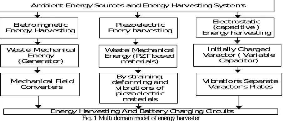
Ambient Energy Sources and Energy Harv esting S ystems
Eletromgnetic Energy Harv esting
Piezoelectric Enery harvesting
Electrostatic (capacitive ) Energy harvesting
Waste Mechanical Energy
(Generator)
Waste Mechanical Energy (PZT based
materials)
Initially Charged Varactor ( Variable
Capacitor)
Mechanical Field Converters
By straining, deforming and
vibrations of piezoelectric
materials
Vibrations S eparate Varactor’s Plates
Energy Harvesting And Battery Charging Circuits Fig. 1 Multi domain model of energy harvester
ISSN (Print) : 2320 – 3765 ISSN (Online): 2278 – 8875
I
nternational
J
ournal of
A
dvanced
R
esearch in
E
lectrical,
E
lectronics and
I
nstrumentation
E
ngineering
(An ISO 3297: 2007 Certified Organization)
Vol. 5, Issue 2, February 2016
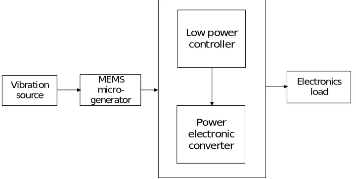
world tothe electronic, it is referred to as a sensor. The accelerometer that is used in gamingcontrollers is an example of such a MEMS sensor. The physical kinetic energy thatis used to maneuver the controller is transduced to an electrical signal that can bepassed to the gaming console.The system is depicted in Fig. 2 is a mechanical system is modeled as a vibration source which couples into the electrical system through the MEMS micro-generator. A low-power controller directs energy conversion and supplies power to the load. The controller consists of a power electronics subsystem which is responsible for exciting the micro-generator through its energy conversion cycle, and has been optimized to minimize losses, and a digital control core which generates the timing pulses which drive the gates of the power FETS or MOSFETS in the power electronics subsystem.
IV. ENERGY SCAVENGING FROM VIBRATIONAL MICRO-GENERATORS
Inertial micro-generators produce electrical energy when subjected to acceleration. Three architectures of inertial micro-generator were identified as suitable for implementation using MEMS technology. All three of these architectures, two of them which are resonant in nature, have been reported in the existing literature. In a study conducted to test the feasibilityand reliability of the different ambient vibrationenergy sources by Marzencki (2005), three differentvibration energy sources (electrostatic,electromagnetic, and piezoelectric) were investigatedand compared according to their complexity,energy density, size, and encountered problems.The study is summarized in Table 1.
The inertial micro-generators have different energy conversion principles and hence they can be classified into three major types that are [3], [25]:
Electromagnetic
Electrostatic
Piezoelectric
3.1 Electromagnetic Micro-Generator
In the electromagnetic micro-generator, mechanical energy is converted into electrical energy by electromagnetic coupling [30]. The conversion technique by which an electromagnetic generator produces electricity is called as the process of electromagnetic induction. A magnet induces current in a coil when it is in motion and the filed lines of the magnet cross the coil. These electromagnetic generators are resonating spring mass damper based systems where the small amplitude surrounding mechanical vibrations are amplified into translational movements larger in amplitude. The mechanical energy of the motion is converted to electrical energy by the process of electromagnetic coupling.
Low power controller
Power electronic converter
Electronics load MEMS
micro-generator Vibration
source
ISSN (Print) : 2320 – 3765 ISSN (Online): 2278 – 8875
I
nternational
J
ournal of
A
dvanced
R
esearch in
E
lectrical,
E
lectronics and
I
nstrumentation
E
ngineering
(An ISO 3297: 2007 Certified Organization)
Vol. 5, Issue 2, February 2016
Table 1: Comparison of Vibrational Energy Sources
Micro-generator type Electro- magnetic Electro-static Piezoelectric
Complexity of process
flow
Very high Low High
Energy density 24.8 mJ cm3 4 mJ cm3 35.4 mJ cm3
Current size Macro Integrated Macro
Problems Very low output
voltages
Very high voltage and need of adding charge source
Low output voltages
Electromagnetic generator uses the permanent magnet and coil arrangement for damping purpose. It can also be called as the VDRG or the velocity damping resonant generator since, the damping force is opposing the proof mass integral velocity and it is best suited for sources that have high frequency and low amplitude [3], [15], [18], [29].
The optimal damping factor ζ is given by ζ =
Where, Yo = source vibration amplitude
= 25 m
And Zl = 1mm
In this case, ζ = 0.0125
The power extracted is hence given by:
P = = ( ) ( )
Where v = proof mass velocity D = damping coefficient
ωn = resonating frequency, where frequency f in Hz is 322Hz
m = proof mass = 0.5 g
The power obtained from the above damper based system is 52mW.
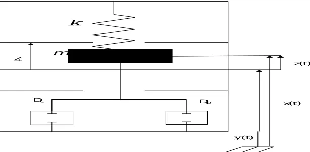
The Fig. 3 depicts the circuitry of a typical inertial electromagnetic micro-generator. A key design choice to process this power circuit is the current and the corresponding voltage at which the power has to be extracted for rectification.To minimize the conduction power loss occurring in the diode in the conventionalswitch diode circuits to the smallest value they must work at voltage above 1V.Even if the synchronous rectification is carried outwith a MOSFET switch, then tooit must bekept in mind that the current value should be minimum and the voltage should have a sufficiently
k
m Zl
Dc Dp
y(t)
x(t) z(t)
ISSN (Print) : 2320 – 3765 ISSN (Online): 2278 – 8875
I
nternational
J
ournal of
A
dvanced
R
esearch in
E
lectrical,
E
lectronics and
I
nstrumentation
E
ngineering
(An ISO 3297: 2007 Certified Organization)
Vol. 5, Issue 2, February 2016
high voltage. To meet this requirement the size of the coil may exceed the available space or it may be difficult to fabricate. Also, if a large size of the coil is utilized then it may increase the number of turns which increases the self-inductance of the coil close to the square of the total number of turns and the induced voltage may increase proportionately. To counteract this, if more conductor material is added to the coil or more turns with the same area of cross section or same turns at greater area of cross section will increase the area over which the flux will be supported in the air gap between the two magnetic materials resulting in greater volume of permanent magnet.
The voltage induced in the generator is
=
Where Ia= active length of coil (length cutting the magnetic field during vibration)
N = number of turns
B = maximum flux density (approx. 1.2 tesla)
For a VDRG micro engineered generator the active length can be taken as 20mm. This will give an induced voltage per turn to be 48mV. Hence, if a single turn is used then the power that may be extracted will be sound 48mV and the impedance of the turn will be very low. Now, if six turns are used instead then too the voltage will be about 300mV, which is very low for the conventional diode rectifiers. The voltage will have to be stepped up by 10 times for use in standard electronics.The literature indicates that often such high voltages are quite difficult to achieve even if the flux gradient, active length and operating frequency are lower.Hence, low voltage rectification and stepping up of the voltage are the basic requirements of inertial micro-generator systems.
3.2 Electrostatic Micro-Generators
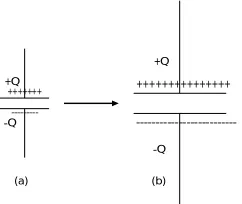
The basic principle outlining the operation of these generators is that a varactor or a variable capacitor can be charged to a low value of voltage at a relatively high capacitance [3], [10], and [25]. But the major disadvantage of working with the electrostatic micro-generators is that at very high voltages they carry very small amount of charge. When the plates of the capacitor are accelerated the capacitance falls down to a low value and this increases the order of voltage to a few hundred volts. The charge must be converter to low voltages for powering the loads. The energy generated is given by:
E = ( − )
By the above equation it is clear that to achieve maximum energy the ratio between maximum and minimum values of the capacitor should be kept high. The main challenge to design such a generator and power converter is the development of parasitic capacitance connected to the generator. There are two types of electrostatic generators:
+++++++++++++++
---+Q
-Q
+++++++
---+Q
-Q
(a) (b)
Fig. 4 Operation of an electrostatic generator in constant charge, (a) and (b) depict the two conditions of the capacitor.
ISSN (Print) : 2320 – 3765 ISSN (Online): 2278 – 8875
I
nternational
J
ournal of
A
dvanced
R
esearch in
E
lectrical,
E
lectronics and
I
nstrumentation
E
ngineering
(An ISO 3297: 2007 Certified Organization)
Vol. 5, Issue 2, February 2016
charge during the generating phase of the cycle (2-3). The capacitor is finally discharged in the third phase (3-1) and the capacitance is again increased to restart the operation. They are traced out by the QV diagram is the electrical energy generated.
Q
V 1
Pre-charge
2 Generate
3
Discharge
(c)
Fig. 5 QV diagram of the constant charge cycle
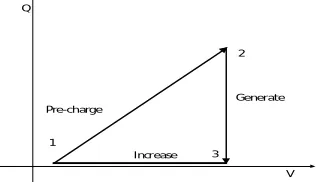
Constant voltage generators:If the capacitor is pre charged, while the capacitor is connected to constant source of voltage, which is usually provided by a battery, motion between the two plates or electrodes would result in charge being transferred to the voltage source and being removed from the capacitor electrodes.The plates are transitioned by a sliding movement.This sliding movement of the capacitor platesmakes the force between the plates in the direction of relative motion almost constant (as shown in Fig. 6).
+++++++
---++++++++
---+Q
-Q
+Q
-Q
(a) (b)
Fig. 6 Operation of an electrostatic micro-generator in constant voltage, (a) and (b) depict the two conditions of capacitor
The Fig. 7 shows QV diagram demonstrating this approach. The previously charged capacitor is set to a voltage when the capacitance is high (1-2). Being connected to the voltage source, which is a battery, the capacitance is decreased forcing the charge back to the source (2-3). This constitutes the generation phase of the cycle. Capacitor is then disconnected from the voltage source by switches before the capacitance value is increased again and (3-1) ready to restart. Area enclosed by the diagram is the energy generated.
Q
V 1
Pre-charge
2
Generate
3 Increase
ISSN (Print) : 2320 – 3765 ISSN (Online): 2278 – 8875
I
nternational
J
ournal of
A
dvanced
R
esearch in
E
lectrical,
E
lectronics and
I
nstrumentation
E
ngineering
(An ISO 3297: 2007 Certified Organization)
Vol. 5, Issue 2, February 2016
3.3 Piezoelectric Micro generator
A piezoelectric material has the ability to convert electrical energy into mechanical energy of deformation (inverse piezoelectric effect-actuator), and also to transform mechanical strain energy into electrical charge (direct piezoelectric effect [1, 2, 3].
Fig. 8 General schematic diagram of a piezoelectric energy harvester
Piezoelectric transducers are a promising choice for microfabricated electric microgenerators, scavenging ambient mechanical energy, are potential power sources for autonomous systems [6, 7]. These devices use bimorph cantilevers because obtaining a damping force is difficult in these devices and they have a low frequency. There are a number of power processingcircuits that convert the piezoelectric energy into usable form [26], [40].Also the piezoelectric devices can produce voltages that can be processed with semiconductor devices directly as shown in Fig. 8. The electrical circuit block diagram of the piezoelectric material is shown in Fig. 9.
Cb
C
E
Vp Vc
Piezoelectric converter
Rectifier and storage capacitor
Sensing and
switching regultorVoltage Transmitter Reciever
Sensor
Oscillator Excitation
Vl+
Vl
-Vosc
Vr+
Vr
-Fig. 9 Block diagram of the developed autonomous piezoelectric system
V. CONVERTER TOPOLOGIES FOR MICRO-GENERATORS
For the micro-generator systems of all the three kinds, electrostatic, electromagnetic or piezo electric, there are certain topologies for the power processing circuits that have been presented previously. Some of those topologies have been briefed here for every micro-generator [3], [10], [12].
ISSN (Print) : 2320 – 3765 ISSN (Online): 2278 – 8875
I
nternational
J
ournal of
A
dvanced
R
esearch in
E
lectrical,
E
lectronics and
I
nstrumentation
E
ngineering
(An ISO 3297: 2007 Certified Organization)
Vol. 5, Issue 2, February 2016
Pulse modulator
Polarity detector
AC
Gate Drive
Gate Drive
Vo Vo
(ref)
Fig. 10 Dual polarity boost converter for electromagnetic energy scavenging micro-generators
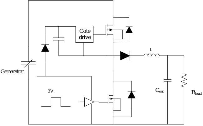
Converters for electrostatic micro-generator energy scavenging: Modified buck circuit was simulated for electrostatic scavenging of micro-generators. They have high voltage blocking capability, around 250V, low junction temperature and low off-state leakage. This was believed to be the simplest method to convert the high voltage on the generator to low voltages [3], [17] and [42].
Gate drive
Cout Rload
3V Generator
L
Fig. 11 A modified buck converter for electrostatic energy scavenging.
The efficiency of the generator can be expressed as a product of two main efficiencies, they are generation efficiency and the conversion efficiencies. For the constant charge mode in electrostatic case it can be expressed as:
ISSN (Print) : 2320 – 3765 ISSN (Online): 2278 – 8875
I
nternational
J
ournal of
A
dvanced
R
esearch in
E
lectrical,
E
lectronics and
I
nstrumentation
E
ngineering
(An ISO 3297: 2007 Certified Organization)
Vol. 5, Issue 2, February 2016
ηconv =
where
Eopen = energy stored in the moving plate capacitor at minimum capacitance
Eclosed = energy of capacitor at maximum capacitance
Wfield = amount of work done against the electric field as the plates separate
Eout = energy available after processing by the converter
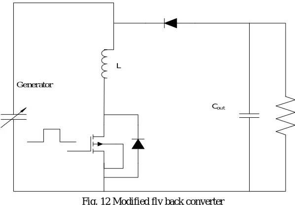
The parasitic capacitance that develops in parallel reduces efficiency of the generation and the conversion efficiency is reduced by switching and conduction losses. Hence, the overall generation efficiency is affected. A buck converter was proposed for the electrostatic energy harvesting to eliminate the short comings of the conventional methods ofbridgeless rectification as shown in Fig. 11.A modified fly back converter was also proposed to scavenge energy from electrostatic micro-generator [39]. The overall effectiveness of a micro-generator is more complex than the efficiency of these power processing circuit. Fig. 12 depicts the modified fly back converter.
Generator
Cou t
L
Fig. 12 Modified fly back converter
ISSN (Print) : 2320 – 3765 ISSN (Online): 2278 – 8875
I
nternational
J
ournal of
A
dvanced
R
esearch in
E
lectrical,
E
lectronics and
I
nstrumentation
E
ngineering
(An ISO 3297: 2007 Certified Organization)
Vol. 5, Issue 2, February 2016
AC
Gate Drive
L
D5 Cout
Battery
1 3 D2 D4
D1 D3 C Res
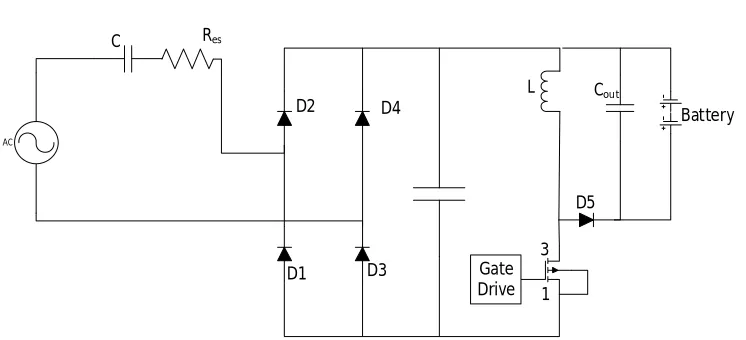
Fig. 13 Buck Boost Converter for Piezoelectric Micro-Generator
converters effectively work at input voltages above or below its output voltage (Vbat). Both these converters must
operate in discontinuous conduction mode (DCM) for higher efficiency [7,8]. Rin =
where:
L= inductance, fSW = switching frequency, and D = duty cycle. Therefore, for a given fSW and D, Rin scales linearly
with L. For large values of Rin, a larger L is necessary. However, this is not desirable since the losses due to the
inductor ESR increase significantly as its value increases. Condition for DCM operation is given by
Vrect< Vbat
Note that if this condition is not adhered to, the converterenters continuous conduction mode (CCM) with
Rin= ( )2
Here, Rin is no longer constant, and the converter will require feedback for adjusting D to obtain constant Rin. This is a serious overhead resulting in lower efficiency, and therefore, must be avoided.
VI. CONCLUSIONS
The paper presented a review of the three basic types of vibrational micro-generators and their respective power processing circuits. The micro-generators that form the basis of the low voltage energy harvesting technique are explained, the broad classification of the microgeneration has been considered with citations from the literary papers. The power converter topologies for the three basic kinds of micro-generators and the previous work done on their respective converter circuits has been discussed. The MEMS technology has been described briefly and the vibrational energy harvesting micro-generators have been discussed and analyzed in detail. Thereafter the power processing circuits for the electromagnetic, electrostatic and piezoelectric micro-generator have been studied.
REFERENCES
[1] W. G. Cady, Piezoelectricity. An introduction to the theory and applications of electromechanical phenomena in crystals, I, II, Dover Publications, New York 1964.
[2] T. R. Hsu, MEMS and Microsystems. Design, Manufacture and Nanoscale Engineering, John Wiley & Sons, Inc., New York, 2008. [3] S. Fatikow, U. Rembold, Microsystem Technology and Micro robotics, Springer Verlag, Berlin, Heidelberg, 1997.
[4] J. Pelesko, Modeling MEMS and NEMS, Chapmann Hall/CRC Press Company, London, New York, 2003. [5] J. Twiefeld, B. Richter, Th. Sattel, J. Wallaschek, J. Electroceram 20, 203 (2008).
ISSN (Print) : 2320 – 3765 ISSN (Online): 2278 – 8875
I
nternational
J
ournal of
A
dvanced
R
esearch in
E
lectrical,
E
lectronics and
I
nstrumentation
E
ngineering
(An ISO 3297: 2007 Certified Organization)
Vol. 5, Issue 2, February 2016
[8] J. A. Paradiso and T. Starner, “Energy scavenging for mobile and wireless electronics,” IEEE Pervasive Comput., vol. 4, no. 1, pp. 18–27, Jan. /Mar. 2005.
[9] S. Dwari, R. Dayal, and L. Parsa, “A novel direct AC/DC converter for efficient low voltage energy harvesting,” in Proc. IEEE Ind. Electron. Soc. Annu. Conf., Nov. 2008, pp. 484–488.
[10] P. D. Mitcheson, T. C. Green, E. M. Yeatman, and A. S. Holmes, “Power processing circuits for electromagnetic, electrostatic and piezoelectric inertial energy scavengers,” Microsyst. Technol., vol. 13, pp. 1629–1635, May 2007.
[11] S. Dwari, R. D. and L. Parsa, “An efficient AC DC step up converter for low voltage energy harvesting,” in Proc. Center Power Electron. Syst. (CPES) Semin. Apr. 2007, pp. 452–456.
[12] M. El-Hami, P. Glynne-Jones, N. M. White, M. Hill, S. Beeby, E. James, A. D. Brown, and J. N. Ross, “Design and fabrication of a new vibration based electromechanical power generator,” Sens. Actuators A: Phys., vol. 92, pp. 335–342, 2001.
[13] T. M. Thul, S. Dwari, R. D. Lorenz, and L. Parsa, “Energy harvesting and efficient power generation from human activities,” in Proc. Center Power Electron. Syst. (CPES) Semin. Apr. 2007, pp. 452–456.
[14] N. G. Stephen, “On energy harvesting from ambient vibration,” J. Sound Vibrations, vol. 293, pp. 409–425, 2006.
[15] J. R. Amirtharajah and A. P. Chandrakasan, “Self-powered signal processing using vibration-based power generation,” IEEE J. Solid-State Circuits, vol. 33, no. 5, pp. 687–695, May 1998.
[16] H. Stark, P. D. Mitcheson, M. Peng, T. C. Green, E. Yeatman, and A. S. Holmes, “Converter circuit design, semiconductor device selection and analysis of parasitics for micro power electrostatic generators,” IEEE Trans. Power Electron., vol. 21, no. 1, pp. 27–37, Jan. 2006.
[17] S. Xu, K. D. T. Ngo, T. Nishida, G. B. Chung, and A. Sharma, “Low frequency pulsed resonant converter for energy harvesting,” IEEE Trans. Power Electron., vol. 22, no. 1, pp. 63–68, Jan. 2007.
[18] J. Elmes, V. Gaydarzhiev, A.Mensah, K. Rustom, J. Shen, and I. Batarseh, “Maximum energy harvesting control for oscillating energy harvesting systems,” in Proc. IEEE Power Electron. Spec. Conf., Jun. 2007, pp. 2792– 2798.
[19] S. P. Beeby, R. N. Torah, M. J. Tudor, P. Glynne-Jones, T. O’Donnell, C. R. Saha, and S. Roy, “Micro electromagnetic generator for vibration energy harvesting,” J. Micromech. Microeng., vol. 17, pp. 1257–1265, 2007
[20] T. Paing, J. Shin, R. Zane, and Z. Popovic, “Resistor emulation approach to low-power RF energy harvesting,” IEEE Trans. Power Electron., vol. 23, no. 3, pp. 1494–1501, May 2008.
[21] Lefeuvre, D. Audigier, C. Richard, and D. Guyomar, “Buck-boost converter for sensorless power optimization of piezoelectric energy harvester,” IEEE Trans. Power Electron., vol. 22, no. 5, pp. 2018–2025, Sep. 2007.
[22] X. Cao,W.J. Chiang,Y.C.King, and Y.K. Lee, “Electromagnetic energy harvesting circuit with feedforward and feedback DC–DC PWM boost converter for vibration power generator system,” IEEE Trans. Power Electron., vol. 22, no. 2, pp. 679–685, Mar. 2007.
[23] G. K. Ottman, H. F. Hofmann, and G. A. Lesieutre, “Optimized piezoelectric energy harvesting circuit using step-down converter in discontinuous conduction mode,” IEEE Trans. Power Electron., vol. 18, no. 2, pp. 696– 703, Mar. 2003.
[24] G. K. Ottman, H. F. Hofmann, A. C. Bhatt, and G. A. Lesieutre, “Adaptive piezoelectric energy harvesting circuit for wireless remote power supply,” IEEE Trans. Power Electron., vol. 17, no. 5, pp. 669–676, Sep. 2002.
[25] M. Ferrari, V. Ferrari, D. Marioli, and A. Taroni, “Modeling, fabrication and performance measurements of a piezoelectric energy converter for power harvesting in autonomous microsystems,” IEEE Trans. Instrum. Meas., vol. 55, no. 6, pp. 2096–2101, Dec. 2006.
[26] Richelli, L. Colalongo, S. Tonoli, and Z.M. Kov´acs-Vajna, “A 0.2−1.2 VDC/DC boost converter for power harvesting applications,” IEEE
Trans. Power Electron., vol. 24, no. 6, pp. 1541–1546, Jun. 2009.
[27] J. C. Salmon, “Circuit topologies for single-phase voltage-doubler boost rectifiers,” IEEE Trans. Power Electron., vol. 8, no. 4, pp. 521–529, Oct. 1993.
[28] HaslinahBintiMohd. Nasir, Mai Mariam Binti Mohamed Aminuddin, “Efficient low voltage amplification using self-starting voltage regulator for storage system,” in International journal of engineering and technology, vol. 6, no. 5, ISSN 0975-4024, Oct-Nov 2014.
[29] P. D. Mitcheson, T. Sterken, C. He, M. Kiziroglou, E. M. Yeatman and R. Puers, “Electrostatic micro-generators.”
[30] M. Ignat, G. Zarnescu, A. L. Catanescu, “Piezoelectric micro-generators for body energy harvesting,” in journal of optoelectronics and advanced materials, vol. 13, May 2011
[31] Y. Rao and D. P. Arnold, Dec.2011 “An input-powered vibrational energy harvesting interface circuit with zero standby power,” IEEE Trans.Power Electron. Vol. 26, no. 12, pp. 3524–3533.
[32] M. R. Sahid, A. H. M. Yatim, TaufikTaufik, 2010, “A New AC-DC Converter Using Bridgeless SEPIC”, IEEE, pp.286-290.
[33] C.B.Williams, C. Shearwood, M. A. Harradine, P. H.Mellor, T. S. Birch, and R. B. Yates,Jun.2001 “Development of an electromagnetic micro-generator,” IEE Proc. Circuits Devices Syst., vol. 148, no. 6, pp. 337–342.
[34] Anoop D Nath, K. Radhakrishnan, Eldhose. K. A, “Low –voltage direct ac-dc boost converter for micro generator based energy harvesting,” International Journal of Advanced Research in Electrical , Electronics and Instrumentation Engineering, vol. 2 issue.3,pp. 1045-1052, Mar.2013. [35] C. Peters, J. Handwerker, D. Maurath, and Y. Manoli, “A sub-500 mV highly efficient active rectifier for energy harvesting applications,”
IEEE Trans. Circuits Syst. I: Reg
[36] S. Cheng, R. Sathe, R. D. Natarajan, and D. P. Arnold,“A voltage multiplying self-powered AC/DC converter with 0.35-V minimum input voltage for energy harvesting applications,” IEEE Trans. Power Electron.,vol. 26, no. 9, pp. 2542– 2549, Sep. 2011.
[37] Y.P. Hsieh, J.F. Chen, T.J. Liang, and L. S. Yang, “A novel high step-up dc–dc converter for a micro grid system,” IEEE Trans. Power Electron., vol. 26, no. 4,pp. 1127–1136, Apr. 2011.
[38] S. Park, Y. Park, S. Choi, W. Choi, and K.-B. Lee, “Soft-switched interleaved boost converters for high step-up and high power applications,” IEEE Trans.Power Electron., vol. 26, no. 10, pp. 2906–2914, Oct.2011.
[39] Haoyu Wang, Yichao Tang, Alirezakhaligh, “A bridgeless boost rectifier for low voltage boost rectifier for low voltage energy harvesting applications,” IEEE Trans. on Power Electron., vol. 28, no. 11, pp. 5206-5214,Nov 2013.
[40] B. Yuan, X. Yang, D. Li, Y. Pei, J. Duan, and J. Zhai,“A current-fed multi resonant converter with low circulating energy and zero-current switching for high step-up power conversion,” IEEE Trans. Power Electron., vol. 26, no. 6, pp. 1613–1619, Jun. 2011.
[41] S. Dwari and L. Parsa, “An efficient high-step interleaved dc–dc converter with a common active clamp,” IEEE Trans.Power Electron., vol. 26, no. 1, pp. 66–78, Jan. 2011.
ISSN (Print) : 2320 – 3765 ISSN (Online): 2278 – 8875
I
nternational
J
ournal of
A
dvanced
R
esearch in
E
lectrical,
E
lectronics and
I
nstrumentation
E
ngineering
(An ISO 3297: 2007 Certified Organization)
Vol. 5, Issue 2, February 2016
[43] Brigttehauke, “basic calculation of a boost converter’s power stage,” application report, SLVA372C, November 2009-revised January 2014 [44] UC Berkeley, “Boost converters,” EECS lab, B. boser
[45] Steven trigno, satyanimmala, romeenrao, “buck-boost converter analysis,” power electronic system design I, winter 2010
[46] R. C. Johnson, \Energy harvesting matures with growth of wireless sensor net-works," Electronic Engineering Times, p. 17, December 3 2007. [47] S. Rodgers and J. Sniegowski, \New ¯ve-level layering process pioneered by sandia promises more reliable, complex micro machines." Sandia
National Laboratories, September 1999. Available at http://www.sandia.gov/media/NewsRel/NR1999/layer.htm. [48] G. T. A. Kovaks, Micro machined Transducers Sourcebook. WCB/McGraw-Hill, 1998.
[49] K. Fu, A. J. Knobloch, F. C. Martinez, D. C. Walther, C. Fernandz-Pello, A. P. Pisano, D. Liepmann, K. Miyaska, and K. Maurta, \Design and experimental results of small-scale rotary engines," in Proceedings of 2001 ASME International Mechanical Engineering Congress and Exposition, November 2001.
[50] A. J. Sprecher, \Microfluidic power generation," Master's thesis, Air Force Institute of Technology, 2008. [51] I. Buchmann, \Battery university," February 2007. Available at http://www.batteryuniversity.com.
[52] Anonymous, \The reality behind Moore's law," Cyber Aspect, January 2008. Available at http://www.cyber-aspect.com/features/feature article.asp?art=104.
[53] Anonymous, \In search of the perfect battery," The Economist, March 6 2008. Available at http://www.economist.com/displaystory.cfm?story id=10789409.
[54] B. S. Lee, P. J. Shih, J. J. He, W. P. Shih, and W. J. Wu, “A study of implantable power harvesting transducers," in Proceedings of SPIE - The International Society for Optical Engineering, Sensor Systems and Networks: Phenomena, Technology, and Applications for NDE and Health Monitoring, vol. 6530, 2007.
[55] O. Cugat, \Magnetic micro-actuators and systems (MAGMAS)," IEEE Transactions on Magnetics, vol. 39, no. 6, pp. 3607{3612, 2003. [56] D. P. Arnold, \Review of microscale magnetic power generation," IEEE Transactions on Magnetics, vol. 43, no. 11, p. 3940(12), 2007.
[57] E. Lefeuvre, A. Badel, C. Richard, L. Petit, and D. Guyomar, \Optimization of piezoelectric electrical generators powered by random vibrations," in Dans Symposium on Design, Test, Integration and Packaging (DTIP) of MEMS/MOEMS, 2006. 98
[58] G. L. Pollack and D. R. Stump, Electromagnetism. Addison Wesley, 2002. [59] P. Kiameh, Electrical Equipment Handbook. McGraw-Hill Higher Education, 2003. [60] P. S. Neelakanta, Handbook of Electromagnetic Materials. CRC Press, 1995. [61] W. Brown, Handbook of Chemistry and Physics. McGraw-Hill, 1958.
[62] T. C. Leichle, M. V. Arx, and M. G. Allen, \A micro machined resonant magnetic field sensor," 14th IEEE International Conference on Micro Electro Mechanical Systems, pp. 274{277, 2001.
[63] G. D. Bari, \Nickel plating," ASM Handbook, vol. 5, 1994.
[64] D. R. Lide, ed., CRC Handbook of Chemistry and Physics. CRC Press, 2003. [65] J. Dean, ed., Lange's Handbook of Chemistry (15th Edition). McGraw-Hill, 1999.
[66] G. S. May and S. M. Sze, Fundamentals of Semiconductor Fabrication. John Wiley and Sons, Inc, 2004.
[67] \AZ P4000 Thick Film Photoresist Datasheet." AZ Electronic Materials, 2005. Available at http://www.az-em.com/PDFs/p4000/az p4000.pdf. [68] A. Ciszewski, S. Posluszny, G. Milczarek, and M. Baraniak, \Effects of saccharin and quaternary ammonium chlorides on the electrodeposition
of nickel from a watts-type electrolyte," Surface and Coatings Technology, vol. 183, pp. 127{133, May 2004. [69] M. Williams, \Electroplating lab notebook." AFRL/RY Devices Cleanroom, 2004.
[70] \LOR and PMGI Resist Datasheet." MicroChem, 2008. Available at http://www.microchem.com.
[71] A. Fitzgerald, C. Kingsley, and S. D. Umans, Electric Machinery - Sixth Edition. McGraw-Hill Handbooks, 2003.
[72] Z. Turgut, \Electromagnetics discussion," January 2007. Air Force Research Lab/Propulsion Directorate, Wright-Patterson Air Force Base. [73] Adler, R., Desmares, P., &Spracklen, J. (1982). Ultrasonic remote control for home receivers, IEEE Trans. Consumer Electronics, 28 (1), 123–
128.
[74] Amirtharajah, R., &Chandrakasan, A. P. (1998). Self-powered signal processing using vibration based power generation. IEEE Journal of Solid-State Circuits, 33 (5), 687-695.
[75] DiSalvo, F. J. (1999). Thermoelectric cooling and power generation. Science, 285, 703-706. [76] Free Play energy, (2007). Retrieved October 5, 2009, from http://www.freeplayenergy.com/products.
[77] Holmes, A. S. (2004). “Axial-flow micro turbine with electromagnetic generator: Design, CFD simulation, and prototype demonstration.” Proceedings of 17th IEEE International Micro Electro Mechanical Systems Conf. (MEMS 04), IEEE Press, 568–571.
[78] Horowitz, S., Kasyap, A., Liu, F., Johnson, D., Nishida, T., Ngo, K., Sheplak, M., &Cattafesta, L. (2002). Technology development for self-powered sensors. Proceedings of 1st Flow Control Conference, St Louis.
[79] Kasap, S.O. (2001). Optoelectronics and photonics: Principles and practices, New Jersey: Prentice-Hall.
[80] Kasyap, A., Lim, J. S., Johnson, D., Horowitz, S., Nishida, T., Ngo, K., Sheplak, M., &Cattafesta, L. (2002). Energy reclamation from a vibrating piezoceramic composite beam. Proceedings of 9th Int. Conference on Sound and Vibration, Orlando.
[81] Kulah, H., &Najafi, K. (2004). An electromagnetic micro power generator for low-frequency environmental vibrations. 17th IEEE International Conference on Micro Eletro Mechanical Systems (MEMS), 237-240.
[82] Lang, S. B. (2005). Pyro electricity: From ancient curiosity to modern imaging tool. Changes in the net dipole moment of certain materials form the basis for a broad range of IR detectors. Retrieved October 5, 2009, from http://www.physicstoday.org/vol-58/iss-8/p31.html
[83] Marzencki, M. (2005). Vibration energy scavenging. European Commission research Project VIBES (IST-1-507911) of the 6th STREP Framework Program.
[84] Mitcheson, P. D., Green, T. C., Yeatman, E. M., & Holmes, A. S. (2004). Analysis of optimized micro generator architectures for self-powered ubiquitous computers. Imperial College of Science Technology and Medicine. Exhibition Road, London, SW7 2BT.
[85] Mikami, S., Tetsuro, M., Masahiko, Y., & Hiroko, O. (2005). A wireless-Interface SoC powered by energy harvesting for short-range data communication. IEEE 0-7803-9162-4/05 2005.
[86] Paradiso, J., &Feldmeier, M. (2001). “A compact, wireless, self-powered pushbutton controller.” ubicomp: Ubiquitous Computing.
ISSN (Print) : 2320 – 3765 ISSN (Online): 2278 – 8875
I
nternational
J
ournal of
A
dvanced
R
esearch in
E
lectrical,
E
lectronics and
I
nstrumentation
E
ngineering
(An ISO 3297: 2007 Certified Organization)
Vol. 5, Issue 2, February 2016
[89] Rabaey, J. M., Ammer, M. J., Da Silva Jr, J. L., Patel, D., & Roundy, S. (2000). Picoradio supports ad hoc “ultra-low power wireless networking.” IEEE Computer, pp. 42–48.
[90] Raffaelle, R., Underwood, J., Scheiman, D., Cowen, J., Jenkins, P., Hepp, A. F., Harris J., & Wilt, D. M. (2000). Integrated solar power systems. 28th IEEE Photovoltaic Specialists Conference, 1370- 1373.
[91] S.Roundy, P.K.Wright, J.Rabaey, “A Study of Low Level Vibrations as a Power Source for Wireless Sensor Nodes”, Computer Communications 26 (2003) 1131-1144
[92] J.L. Gonzàlez, A. Rubio, F. Moll., “Human powered piezoelectric batteries to supply power to wearable electronic devices”, International Journal of the Society of Materials Engineering for Resources A 10 (2000), 34-40.
[93] J. Kymissis, C.J. Kendall, J. Paradiso, N. Gershenfeld. “Parasitic power harvesting in shoes.” Proc. of 2nd IEEE Int. Conference on Wearable Computers (ISWC), October 1998, pp. 132-139.
[94] T. Sterken, K. Baert, C. VanHoof, R. Puers, G. Borghs, P. Fiorini, “Comparative Modelling for Vibration Scavengers”, Proc. of IEEE Sensors 2004, 24-27 October, Vienna, 1249-1252.
[95] P.Glynne-Jones, M.J.Tudor, S.P.Beeby, N.M.White, “An electromagnetic, vibration-powered generator for intelligent sensor systems”, Sensors and Actuators A 110 (2004) 344–349.
[96] Despesse G, Jager T, Basrour S, Chaillout JJ, Charlot B, Leger JM, Vassilvev A (2005) “High damping electrostatic micro devices for vibration scavenging.” In: DTIP of MEMS/ MOEMS, Montreux, June 1–3, 2005, pp 386–390
[97] Guyomar D, Badel A, Lefeuvre E, Richard C (2005) “Toward energy harvesting using active materials and conversion improvement by nonlinear processing.” IEEE Trans UltrasonFerroelectrFreq Control 52:584–595
[98] Meninger S, Mur-Miranda JO, Amirtharajah R, Chandrakasan A, Lang JH (2001) “Vibration-to-electric energy conversion.” IEEE Trans Very Large Scale Integration (VLSI) Syst 9:64– 76
[99] Mitcheson PD, Miao P, Stark BH, Yeatman EM, Holmes AS, Green TC (2004b) “MEMS electrostatic micropower generator for low frequency operation.” Sens Actuators 115:523–529
[100] Roundy S, Wright PK, Rabaey JM (2003) “Energy scavenging for wireless sensor networks.” Kluwer, Boston
[101] Stark BH, Mitcheson PD, Miao P, Green TC, Yeatman EM, Holmes AS (2006) “Converter circuit design, semiconductor device selection and analysis of parasitics for micropower electrostatic generators.” IEEE Trans Power Electron 21:27–37
[102] P. D. Michelson, T.C. Green, E. M. Yeatman, and A. S. Holmes, “Architecture for vibration-driven Micropower generators, ”Microelectromech. Syst., vol. 13, no. 3, pp. 429–440, Jun. 2004
[103] Rohan Dayal, Suman Dwari, Leila Parsa, ”A New Design for Vibration-Based Electromagnetic Energy Harvesting Systems Using Coil Inductance of Micro generator”, IEEE Transactions on Industry Applications. Vol.47, No.2, March/April 2011.
[104] Enrico Dallago, MarcoMarchesi, and Giuseppe Venchi, “Analytical Model of a Vibrating Electromagnetic Harvester Considering Non- linear Effects”,IEEE Transactions On Power Electronics’ Vol.25, No. 8,August 2010
[105] Staley M E and Flatau A B, Characterization of energy harvesting potential of Terfenol-D and Galfenol,” Proceedings of SPIE, 2005, pp 630-640.
[106] Tashiro R, Kabei N, Katayama K, Tsuboi F and Tsuchiya K, “Development of an electrostatic generator for a cardiac pacemaker that harnesses the ventricular wall motion,” Journal on Artifcial Organs, 2002, pp 239–245.
[107] Tashiro R, Kabai N, Katayama K, Ishizuka Y, Tsuboi F and Tsuchiya K, “Development of an electrostatic generator that harnesses the motion of a living body,” JSME International Journal Series C, 2000, c 43, pp 916–922.
[108] Umeda M, Nakamura K and Ueha S, “Analysis of the transformation of mechanical impact energy to electric energy using piezoelectric vibrator,” Japan, Journal of Applied Physics, 1996, v 35, pp 3267–3273.
[109] Umeda M, Nakamura K, and Ueha, S, “Energy Storage characteristics of a piezo-generator using impact induced vibration”, Journal of Applied Physics, 1997, v 36, pp 3146- 3151.
[110] Wang L and Yuan F G, “Energy harvesting by magnetostrictive material (MsM) for powering wireless sensors in SHM,” SPIE Smart Structures and Materials & NDE and Health Monitoring, 14th International Symposium (SSN07), 18-22 March, 2007.
[111] Warneke B, Last M, Liebowitz B and Pister K S J, “Smart Dust: communicating with a cubic- millimeter,” Journal of Computer, January 2001, v 34, pp 44-51.
[112] White N M, Glynne-Jones P and Beeby S, “A novel thickfilm piezoelectric micro-generator,” Smart Material Structures, August 2001, v 10, pp 850–852.
[113] Williams C B and Yates R B, “Analysis of a micro-electric generator for microsystems,” in proceedings of Solid-State Sensors and Actuator and in Eurosensors IX. Transducers, 1995, v 1, pp 369–372.
[114] Williams C B, Pavic A, Crouch R S, and Wood R C, “Feasibility study of vibration-electric generator for bridge vibration sensors,” IMAC-Proceedings 16th International Modal Analysis Conference, 1998, v 32, pp 1111-1117.
[115] Snarski S R, Kasper R G and Bruno A B, “ Device for electro-magnetohydrodynamic (EMHD) energy harvesting,” Proceedings of the SPIE, 2004, v 5417, pp 147-161.
[116] Sodano H A, Dereux R, Simmers G E, and Inman D J, “Power Harvesting Using Thermal Gradients for Recharging Batteries,” Proceedings of 15th International Conference on Adaptive Structures and Technologies, Bar Harbor, ME, October 25–27 2004
[117] Sodano H A, Inman D J, and Park G., “A Review of Power Harvesting from Vibration Using Piezoelectric Materials,” The Shock and Vibration Digest, 2004, v 36, pp. 197–205.
[118] Sodano H A, Inman D J and Park G, “Comparison of Piezoelectric Energy Harvesting Devices for Recharging Batteries,” Journal of Intelligent Material Systems and Structures. 2005, v 16, pp 799-807.
[119] Sodano H A, Simmers G E, Dereux R, and Inman D J, “Recharging Batteries using Energy Harvested from Thermal Gradients,” Journal of Intelligent Material Systems and Structures, January 1, 2007, v 18, pp 3 - 10.