Performance Comparison of Energy
Efficiency of Transmitter in MIMO
Decode-and-Forward Relay Channels
Anunchitha
PG Student [Communication Engg.], Dept. of ECE, Vedavyasa Institute of Technology, Malappuram, Kerala, India
ABSTRACT: Cooperative communication has achieved major research concern due to its ability to enlarge system coverage and improve spectrum efficiency. Consider, a transmit cooperative beamforming design, for the scenario with multiple-input-multiple-output (MIMO) decode-and-forward (DF) relay channel with a direct source to destination link. The achievable information rate (bits/s) for a given transmit signal-to-noise ratio (SNR) for a particular beamforming scenario is calculated based on the optimal beamforming vectors obtained. Results show that when multiple numbers of antennas are deployed at all the nodes the achievable information rate is higher. Also, the energy efficiency of the transmitter is improved when the destination is equipped with multiple number of antennas.
KEYWORDS: Beamforming, Decode-and-forward, Energy efficiency, MIMO and SNR
.
I. INTRODUCTION
Relay plays an imperative and vital role in the field of communication by improving the coverage extension and providing efficient signal transmission particularly in the case of wireless systems by achieving spectral efficiency. There are two types of relay strategies: Amplify and forward (AF) and Decode and forward (DF). In case of amplify and forward (AF), the relay simply amplifies its received signals and then forwards them to the destination, and in case of decode and forward (DF), the relay decodes the received signals and then again forwards the re-encoded information to the destination. In condition, when the source-relay channel is statistically better than the source-destination and relay-destination channels the DF relay is much better than the AF relay[1].
MIMO systems have huge potential for getting better system throughputs. The use of antenna arrays at both ends of the communications link can make use of the spatial dimension, which is an additional system resource [2]. Multiple antennas may be used to perform smart antenna functions such as spreading the total transmit power over the antennas to achieve an array gain that incrementally improves the spectral efficiency and/or achieving a diversity gain that improves the link reliability (reduces fading). Thus, by deploying multiple numbers of antennas at wireless terminals or nodes in a scenario can prove beneficial to the system by improving various dominant factors like the channel capacity, reliable transmission and effective diversity combining.
II. RELATED WORK
Most of the earlier works on MIMO relay channels mainly focused on the network capacity from the information theoretic perspective. More recently only the MIMO relay beamforming design has started to receive growing interest. Most work on the DF MIMO relay beamforming assumed that no direct link exists between the source and the destination [3]. However, so far, little research has addressed the combination of MIMO beamforming and power control for both interference management and energy utilization of MIMO network model.
MIMO DF Relay communication system as in [4] is considered. It is found that when transmitter of the communication system with MIMO DF relay scenario where the destination is also equipped with multiple numbers of antennas is compared with the existing MIMO DF relay scenario with single antenna at destination and the energy efficiency of the former is found to be better in most of the scenarios.
The rest of the paper is organized as follows. Section III describes the system model and the mathematical formulation of the beamforming scenario. Section IV describes about the energy efficiency of the transmitter. Section V includes simulation results and discussion and the paper ends with few concluding remarks in Section VI.
III. SYSTEM MODEL
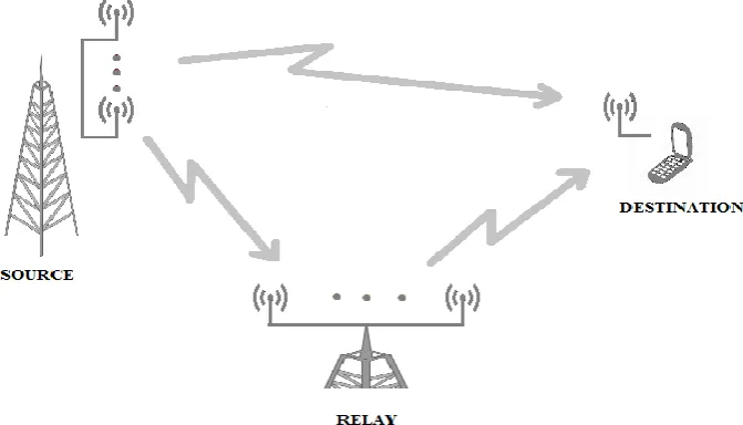
Consider a communication system model consisting of source S, a relay R and a destination D as shown in Fig. 1. It is assumed that direct link exist between S – R and relay R helps in retransmitting the information to the destination D. Consider two phases, first phase the source transmits information to relay and destination, and in second phase relay re-transmits the information received from source to the destination. Thus, destination obtains the desired information by decoding the combined signals received over the abovementioned two phases. In first phase, let the information symbol
xs be multiplied with beamforming vector wsbefore being transmitted. Let Ns be the number of antennas at the source
node. Assume that the average power at the source node be Ps and the ws is a unit-norm vector.
Fig. 1 System model of the three-node MIMO DF relay channel
The received information at D in the first phase is given by
y
D S,
h
TD S,w x
s s
n
D S, (1) where hD,S denotes the channel gain vector from S to D and nD,S is scalar additive Gaussian noise with unit variance. It follows that the received signal to noise ratio (SNR) at D during this first phase is given by* ,
2 ,
(
)
D S|
|
T s
D S S
SNR
h
w
P
(2) Similarly, the information received at R is given as
y
R S,
H
R S,w x
s s
n
R S. (3) where HD,R denotes the channel gain matrix from S to R and nD,R is scalar additive Gaussian noise with unit variance. Thus, the received SNR at R is
(
SNR
)
*R S,
||
H
R S,w
s||
2P
s (4) So, the achievable information rate from S to R isIn the second phase, the relay re-transmits the information received from the source to the destination, xr, with average
power Pr with the beamforming vector wr as given
y
D R,
h
D RT,w x
r r
n
D R, (6) where hD,R denotes the channel gain vector from S to D and nD,R is scalar additive Gaussian noise with unit variance. It follows that the received SNR at D in second phase is
(
SNR
)
*D R,
|
h
D RT,w
r|
2P
r (7) Later, D combines the signal received from R and S using Maximum Ratio Combining (MRC). The achievable information rate at D in second phase is given by
I
D
log (1 (
2
SNR
)
*D S,
(
SNR
)
*D R,)
(8)Thus, its well known that the maximum information rate is bounded by ID and IR in [4]. Therefore, the total achievable information transmission rate at D from S over the MIMO DF relay channel is given by
2 *, 2 *,
* ,
1
min{ , }
2
1
min{log (1 (
)
), log (1 (
)
2
(
)
)}
DF R D
DF R S D S
D R
I
I I
I
SNR
SNR
SNR
(9)Thus, the optimisation to be done in the following equation to get the optimal beamforming vectors
* * *
2 , , ,
,
2 2
1
max
log (1 min((
)
, (
)
(
)
))
2
. ||
||
1,||
||
1
s r R S D S D R
w w
s r
SNR
SNR
SNR
s t w
w
(10)
Thus, according to the optimisation in [4] for getting the optimal beamforming vectors so as to maximise the achievable information rate can be obtained by solving (10).
IV. ENERGY EFFICIENCY OF TRANSMITTER
By incorporating multiple numbers of antennas at the destination the energy efficiency of the transmitter can be improved further. The system model of MIMO DF relay channel is improvised with multiple number of antennas at all the nodes. As far as energy efficiency of transmitter is concerned the total power consumption along the signal path of a link can be divided into two main parts: the power consumption of the power amplifiers (PPA), and the power consumption of all other circuit blocks (PC). The power consumed by the power amplifiers PPA , can be modelled as
P
PA
.
P
T (11) the reciprocal of the power amplifier efficiency (β), which is assumed to be a constant, PT is the total transmit power.The circuit power PC includes the power consumed by the digital signal processor (DSP), frequency synthesizer, mixer, etc. The power consumption of the DSP should be the dominant component and mainly depends on the number of computations required for a given algorithm. There are several different ways to evaluate this circuit power. In [6] and [9] the circuit power is the sum of the power consumed in the circuit blocks (not including the DSP). Since accurately quantifying PCis still an open issue, here, as in [10], assume that PCis fixed and consider different values for PCin the simulations.Thus, as in [11] the energy efficiency (in bits/Joule) of the kth link can be written as
.
.
k DF
Tr
K C
B I
P
P
(12) where, B is the bandwidth. The numerator in (12) is the rate (in bits/sec) achieved according to the MIMO DF relay cooperative beamforming design, and the denominator is the total power consumption during transmission over the kthThus, with the fixed circuit power and also based on the achievable information rate obtained in the scenario i.e. MIMO DF relay and proposed MIMO DF relay with multiple number of antennas in the destination as per the beamforming design in [4] and the energy efficiency of transmitter based on the aforementioned situation is calculated.
V. RESULTS AND DISCUSSION
The effectiveness of proposed optimal beamforming design for MIMO DF relay channels is showed through numerical examples with the assumption that the power Ps = Pr = P in all simulations. Rayleigh fading channel model is adopted in simulations, where it generate all the elements of channel gain matrix from complex Gaussian distribution with zero mean and unit variance.
The cooperative beamforming communication network model consists of source, relay and destination. The number of antenna equipped at source, relay and destination is Ns, Nr and Nd respectively. The simulation results for energy efficiency of transmitter is shown for various scenarios represented as Ns : Nr : Nd. Also in the simulation, the power amplifier efficiency is assumed to be 38%.
Fig. 2 Comparison of achievable information rate in optimal beamforming in scenario 4:4:2 vs. 4:4:1
In Fig. 2 the comparison between the two scenarios 4:4:2 and 4:4:1 is shown for the achievable information for 100 to 1000 sample channel realization where k represents the index of samples. It is seen that the scenario with destination equipped with multiple number of antennas outperforms the destination with single antenna.
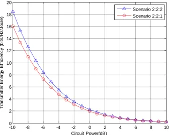
In Fig 3 the comparison between the two scenarios 2:2:2 and 2:2:1 in the energy efficiency of transmitter for circuit power consumed is plotted and it’s shown that 2:2:2 scenario perform better when compared to the 2:2:1. The circuit power is kept fixed and the efficiency is calculated for the information rate achieved in the given scenarios.
100 200 300 400 500 600 700 800 900 1000
-2 -1 0 1 2 3 4 5 6 7 8
k-channel realization
A
c
h
ie
v
a
b
le
I
n
fo
rm
a
ti
o
n
r
a
te
(b
it
s
/s
)
Fig. 3 Comparison of energy efficiency of transmitter in scenario 2:2:1 vs. 2:2:2
Fig. 4 Comparison of energy efficiency of transmitter in scenario 4:2:1 vs. 4:2:2
-10 -8 -6 -4 -2 0 2 4 6 8 10
0 2 4 6 8 10 12 14 16 18 20 Circuit Power(dB) T ra n s m it te r E n e rg y E ff ic ie n c y ( b it s /H z /J o u le ) Scenario 2:2:2 Scenario 2:2:1
-10 -8 -6 -4 -2 0 2 4 6 8 10
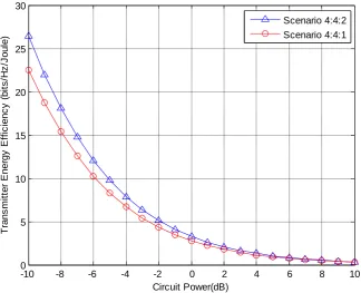
Fig. 5 Comparison of energy efficiency of transmitter in scenario 4:4:1 vs. 4:4:2
Similarly, in the Fig 4 the comparison between the two scenarios 4:2:2 and 4:2:1 in the energy efficiency of transmitter for circuit power consumed is plotted and it’s shown that 4:2:2 scenario perform better than 4:2:1. It can be noticed that as the number of antennas deployed at the nodes are increasing the efficiency of the transmitter is also increasing accordingly.In Fig. 5 the comparison between the two scenarios 4:4:2 and 4:4:1 in the energy efficiency of transmitter for circuit power consumed is plotted and it’s shown that 4:4:2 scenario perform better when compared to the 4:4:1. Thus, it’s noticeable that in all the scenarios the energy efficiency of the transmitter in MIMO DF relay is found to be better when the destination is equipped with multiple number of antennas. Also, as the number of antenna at each node is increasing the energy efficiency also increases.
VI. CONCLUSION
In this work, the beamforming design for MIMO DF relay channels, where the source node, relay node and destination node are equipped with multiple antennas with an assumption that a direct link exist between source and destination is considered. The capacity formulation is done based on the optimal beamforming vectors obtained for maximising the achievable information rate for given transmit SNR value. Also, the use of multiple number of antennas at the destination increases the performance. The results also show that the energy efficiency of the source i.e. the transmitter is better when the destination is also equipped with multiple number of antennas.
REFERENCES
[1] R. U. Nabar, H. Boölcskei, and F.W. Kneubühler, “Fading relay channels: Performance limits and space-time signal design,” IEEE J. Sel. Areas Commun., vol. 22, no. 6, pp. 1099–1109, Aug. 2004.
[2] A. Goldsmith, Wireless Communications. Cambridge University Press, 2005.
[3] T. C. Y. Ng and W. Yu, “Joint optimization of relay strategies and resource allocations in cooperative cellular networks,” IEEE J. Sel. Areas Commun., vol. 25, no. 2, pp. 328–339, Feb. 2007.
[4] Ke Xiong, Pingyi Fan, Zhengfeng Xu, Hong-Chuan Yang, and Khaled Ben Letaief, “Optimal Cooperative Beamforming Design for MIMO Decode-and-Forward Relay Channels” IEEE Trans. Signal Processing, Vol. 62, No. 6, March 15, 2014
[5] G. Miao, N. Himayat, G. Y. Li, and A. Swami, “Cross-layer optimization for energy-efficient wireless communications: a survey,” Wiley J. Wireless Commun. Mobile Comp., vol. 9, no. 4, pp. 529–542, Apr. 2009.
-10 -8 -6 -4 -2 0 2 4 6 8 10
0 5 10 15 20 25 30
Circuit Power(dB)
T
ra
n
s
m
it
te
r
E
n
e
rg
y
E
ff
ic
ie
n
c
y
(
b
it
s
/H
z
/J
o
u
le
)
[6] S. Cui, A. J. Goldsmith, and A. Bahai, “Energy-efficiency of MIMO and cooperative MIMO techniques in sensor networks,” IEEE J. Sel. Areas Commun., vol. 22, no. 6, pp. 1089–1098, Aug. 2004.
[7] E. V. Belmega and S. Lasaulce, “Energy-efficient precoding for multipleantenna terminals,” IEEE Trans. Signal Process., vol. 59, no. 1, pp. 329–340, Jan. 2011.
[8] Z. Chong and E. A. Jorswieck, “Energy efficiency in random opportunistic beamforming,” in Proc. 2011 IEEE VTC – Spring.
[9] A. Wang, S. Chao, C. Sodini, and A. Chandrakasan, “Energy efficient modulation and MAC for asymmetric RF microsensor system,” in Proc.2001 Int’l Symp. Low Power Electron. Design, pp. 106–111.
[10] G. Miao, N. Himayat, G. Y. Li, and D. Bormann, “Energy-efficient design in wireless OFDMA,” in Proc. 2008 IEEE ICC, pp. 3307–3312. [11] Chenzi Jiang and Leonard J. Cimini, Jr. “Energy-Efficient Transmission for MIMO Interference Channels”, IEEE Trans. Wireless
Communications, Vol. 12, No. 6, June 2013