Study on Irregularly Shaped Shotcrete
Shells in Tunnel-A Case Study
KANDRAKOTA SRI ANANDHINI PG Student
Dept. of Civil Engineering BVC ENGINEERING COLLEGE ODALAREVU
email:[email protected]
Dr. D S V PRASAD Professor & Principal Dept. of Civil Engineering BVC ENGINEERING COLLEGE ODALAREVU
email:[email protected]
ABSTRACT: In most large infrastructure projects where the tunnels yesterday's shotcrete part of rock reinforcement. Shotcrete is admixture of concrete, total, water and different added substances, for example, quickening agents that showered on such a stone surface. It is additionally conceivable to utilize steel strands in this blend, which go at a considerably greater tensile strength. In this case, usually rock reinforcement also consistsof rock bolts, which bolts are different in length among others can be embedded in the rock. These can then be with washers on the outside of the concrete surface to prevent excessive tension will occur at the bolts. Regularly, experimental techniques or suspicion that the shower solid goes about as a solid chunk to decide how shake support ought to be designed Normally, observational strategies or supposition that the splash solid goes about as a solid section to decide how shake fortification ought to be planned. This provides a rock reinforcement that can probably be oversized, which means that there is a need of design methods that provide an accurate picture of how the shotcrete work. Previously numerical models used to investigate a sprayed concrete reinforcement. This work is a preliminary study to a larger research project on shotcrete. The report reviewing the existing literature on the fields, trying to describe the practical problems occurs during construction, and using a development of the numerical model previously used to analyze the same problem in 3D. The outcomes demonstrate that the conclusions made before are moderately well in 3D and that few of the finishes of the prior review likewise predictable with this model. This review closes with proposals for further research and stresses the need to utilize the stone mass as a major aspect of rock support in future models, where particularly the bond that happens amongst shotcrete and rock is an imperative parameter in light of the fact that the quantity of violations in the shotcrete appears cooperate with this parameter.
KEYWORDS: Shotcrete, Accelerators, Steel Fibers, Tensile Strength, Reinforcement.
I.INTRODUCTION
II.PREVIOUSWORK
The model developed by Nilsson (2003), is the basis of the numerical modelling presented in this report, which depends on the same geometrical and material properties. The numerical reproductions of enthusiasm for this report comprise of a parameter investigation of a sporadic shotcrete slab. The parameters examined were the inconsistency of the slab, the thickness of the slab, the position of the rock jolts and the limit conditions utilized as a part of the recreations. The solidness of the slab was in a roundabout way changed as the thickness and shape was changed.
Two diverse sporadic slabs were utilized. The first was quadratic and 4 x 4 m2, with a rock jolt set amidst the slab. The other was 6 x 6 m2, with rock jolts set either at the pinnacles of the slab or at the discouragements of the slab. Comparative reproductions were additionally performed on a level slab to think about the impacts of the anomaly. Two different thicknesses on the shotcrete slab were used, 40 mm and 80 mm, both for the irregular slabs and the flat slabs. The heap from the rock mass was reproduced by a consistently conveyed stack on the surface of the slab. Two diverse limit conditions were used, simply supported ends and fixed ends.
I.DESIGN ANDCONSTRUCTION
A. DESIGN
The design is usually based on empirical methods, which means that the experience from earlier projects is used to give an estimation of what will be a reasonable rock support. For any run of the mill Q-esteem or RMR Q-esteems (rock mass rating) or some other experimental parameter (clarified underneath) will give a "run of the mill rock support",based onexperience. The design work will give the construction firm three design values can be changed contingent upon the states of the rock surface after the boring and impacting. The Q-esteem or RMR-values rely on upon the measuring strategy. They development firm will be given very nitty gritty direction for each piece of the passage. The predefined configuration elements thatare:
Shotcrete lining thickness Shotcrete liningstrength Rock boltdistance
B. CONSTRUCTION
The shotcrete lining is just one part of the construction phase which consists of a large organization with many people with different knowledge of the different parameters that affect the
ground. They workplace tends be limited in volume and communication is very difficult, according to Nord and Stille. Because of all these factors it is very important to have simple blueprint and construction directions. The time is also very important since the opening date for the tunnel is usually decided, and the whole project will be influenced by this. Time is often more important than cost when the economic benefits will be quite small.
The construction firm will start spraying the shotcrete lining after the drill and blast has been done. The drill and blast procedure includes:
Pre-grouting
Drilling
Charging
Blasting
Scaling
Mucking
II.ASSUMPTIONS AND SIMPLIFICATIONS USED IN THEANALYSIS
MODELANALYZED
A heap that reenacts the drive from a solitary rock is connected on top of the shotcrete lining. The heap comprises of uniform weight. The position of the load is shown in Figure.
Figure shows the load from a single rock on the shotcrete lining. In this case, the cracks in the rock mass cannot restrain the rock, which instead will be carried by the shotcrete lining.
The load will consist only of pressure, and hence will not have any stiffness. This is fairly implausible, since a genuine rock has solidness and could redistribute the heap when the rock support is changed, for instance if there is a disappointment in some piece of the rock bolster that is subjected to the heap from the rock. The heaps are once in a while conveyed by the shotcrete lining, and in different situations where the rock arrangements are huge, at least one rock screws will be connected at the surface of the single rock to secure it against whatever remains of the rock mass. Three distinct varieties of the model will be utilized: the standard model, the sporadic one with the rock jolts at the pinnacles and the unpredictable one with the rock jolts at the dejections. The thickness of the shotcrete coating is changed from 25 mm to 125 mm for the three unique models however is uniform for every one of the three models, with a specific end goal to concentrate the impact of the shotcrete thickness. The rock jolt that will be subjected to the most astounding burdens will speak to the covering when the greatest foremost compressive and tractable anxieties and the impact length are figured. The underlying recreations demonstrated that the most extreme ductile and compressive important anxieties dependably showed up at the edges of the washers appended to the rock jolts. In the principal case where the heap impact was mimicked by a uniform weight on the passage roof, the rock jolt washers nearest to the zone subjected to the heapwere obliviously most affected.The maximumprincipalstress has been defined as the highest stress that converges along the edge of the rock bolts washers. Since the washers are simulated by quadratic elements there is a theoretical divergence at the edge of the rock bolt. Instead the
highest value that converges by the edge of the rock bolt washer has been used.
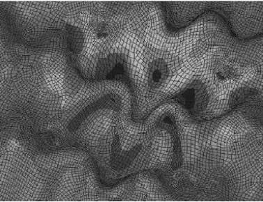
The deflection of the tunnel ceiling in the middle of the area that is subjected to the load will also be collected from the model. The influence of the high tensile principal stresses along the edges of the rock bolts have been estimated by using the “influence length” of the stress distribution. This has been estimated as the multiple of the rock bolt length that
has been subjected to more than 80 % of the maximum tensile stress. An example is shown in Figure, where the influence length is1.2.
Fig 1: Influence Length of The Maximum Tensile Principal Stress Along the Edge of The Bolt
Washer Where the Influence Length Is 1.2 The following results will be collected from the numerical simulations:
Maximum principal tensile stress at the rock bolt subjected to the largest load.
Maximum principal compressive stress at rock bolt subjected to the largest load.
Influence length at rock bolt subjected to the largest load.
Deflection of the tunnel ceiling relative to the vertical axes.
The aims are to:
Identify the differences between the stress distributions of the models.
Estimate the possible damage of the models depending on the shotcrete thickness.
Estimate the stiffness of the different models depending on the shotcrete thickness.
Assess the difference between the rock bolt placement patterns
V.RESULTS
The results for the above model shows that the shape of the shotcrete lining influences the stresses in the lining significantly. The numerical investigation demonstrated that both the most extreme elastic anxieties and the greatest compressive burdens were situated at the jolt washers.
contrasted with the customary coating. It likewise affirms the outcome that the rock jolt design where the jolts were set at the pinnacles of the surface abnormalities had a higher load bearing limit contrasted with the example where the rock jolts were put at the sorrows of the surface inconsistencies. The distinction between the sporadic and the general shotcrete linings appears to increment when the thickness expands, which implies that the outcomes are fairly extraordinary.
The burdens were situated along the edges of the jolt washers, yet the correct area along the jolt washer depended incredibly on the shotcrete thickness. The circulation of the greatest principals worries along the edge of the jolt
washers, where the anxiety focalizes to the edge nearest to the heap as the shotcrete thickness increments. The dim regions symbolize roughly 80 % of the greatest burdens. In-situ, the jolt washer could likely move and turn to some degree contrasted with the model where no development or pivot was permitted along the surface of the jolt washer. This could lessen the most extreme important worries at the washer.
The base key worries along the edge of the jolt washer will carry on in an unexpected way. This example has perceptible higher compressive worries at the rock jolts, particularly when the shotcrete covering is thin, yet the distinction diminishes as the shotcrete lining thickness increment. As the thickness of the coating expands, it appears that the general shotcrete covering will have higher compressive anxieties contrasted with the unpredictable fixing with any of the blasting example. This may propose that the anxiety is re-dispersed distinctively in the general covering when the thickness increments than for the unpredictable fixing with either catapulting design.
As already expressed, the impact of the weights on the heap bearing limit of the coating was additionally explored by
utilizing an estimation of the burdens that can be known as the impact length. This is the proportion between the
lengths of the anxiety that outperform 80 % of the greatest central worries along the jolt washer, contrasted with the
length of the jolt washer. This ought to be a to some degree precise estimation of the harm perpetrated by the heap.
Fig. 2: Minimum Principal Stress Along the Bolt Washer
It affirms the outcomes from which demonstrates that when the rock jolts are put at the sorrows of the surface, in can diminish the heap bearing limit contrasted with the general coating. This sporadic model with the blasting example at the pinnacles of the abnormalities is ideal contrasted with both the customary covering and the rock jolt design where the rock jolts are put at the sorrows of the anomalies.
The distinction in stress circulation around various jolts if the rock jolts are set discretionarily along the shotcrete lining. Clearly the rock jolts that are set on the dejections of the shotcrete lining offer ascend to higher most extreme foremost worries than the rock jolts put at the pinnacles of the shotcrete lining. This likewise affirms the conclusions advanced that the shotcrete around rock jolts put at the pinnacles are overwhelmed by compressive worry rather than tractable anxiety. For the rock jolts set at the sorrows of the shotcrete covering, the circumstance is switched, and they are encompassed by high pliable anxieties.
Fig.3. shows the deflection in the lining ceiling for different shotcrete thicknesses. It is obvious that the regular shotcrete lining has a much higher flexibility compared to the irregular lining with any rock bolt pattern. The outcomes likewise demonstrate that the rock jolt design with the rock jolts put at the despondencies brings about a coating that has a higher solidness than the rock jolt design with the rock jolts set at the pinnacles of the inconsistencies. This impact likewise increments when the thickness of the shotcrete liningdecreases.
Fig 3. Stress Distribution for A Shotcrete Lining with Rock Bolts Placed Arbitrarily Along the
V. CONCLUSION
The state of a passage divider after the assignment of impacting and boring is ordinarily unpredictable. After the passage divider is splashed with shotcrete, the subsequent shotcrete surface will also be irregular and have a big variation in thickness due to uneven shotcrete coverage. Today, most design models assume that the shotcrete surface behaves as a concrete slab. The existing literature on the subject is reviewed to gain an understanding of the important parameters that affect the shotcrete shell. In addition to the theoretical research the relevant parameters that influence the behavior of a tunnel lining are discussed and the quantitative and qualitative importance of each parameter is estimated. Someof the practical problems that arise when a shotcrete lining is constructed are discussed. These problems complicate the design in many ways, and makes shotcrete design very different from ordinary structural design. The behavior of a shotcrete rock support system subjected to several load combinations using different models that simulate irregularity and variation in thickness is analyzed. The results show that the influence of the irregularity is highly dependent on the shotcrete thickness and shape and that the placement of the rock bolts is very important. Several other aspects are discussed aswell.
REFERENCES
1. Borio L, Peila D, 2009. “Influence of tunnel shape on lining stresses”, ITA–AITES world tunnel congress 2009 and the 35th ITA–AITES general assembly, Budapest, May 23–28, 2009.
2. Oreste P, 2003. “A procedure for determining the reaction curve of shotcrete lining considering transient conditions”, Rock mechanics and rock engineering. Vol. 36, No. 3, pp. 209-236.
3. Peck R.B, Hendron A.J, Mohraz B, 1972. “State of the art of soft-ground tunnelling”, Proceedings of the North American rapid excavation and tunnelling conference, Chicago, pp. 259-286.
4. Son M, Cording E.J, 2006. “Ground-liner interaction in rock tunnelling”, Tunnelling and underground space technology. Vol. 22, No. 1, pp. 1- 9.
5. Malmgren L, Nordlund E, 2008. “Interaction of shotcrete with rock and rock bolts – a numerical study”, International journal of rock mechanics and mining sciences. Vol. 45, No. 4, pp. 538- 553.
6. Bryne E L, Ansell A, Holmgren J. Laboratory testing of early age bond strength of shotcrete on hard rock. Tunnelling and Underground Space Technology. 2014 mar; 41:113–119.
7. Oliver J, Cervera M, Oller S, Lubliner J. Oliver-1990- Isotropic damage models and smeare.pdf. Computer Adided Analysis and Design of Concrete Strucutres. 1990; p. 945–957.
8. Bazant P Z, Najjar J L. Nonlinear water ˇ diffusion in nonsaturated concrete. Matriaux et Construction. 1972;(1):3–20.
9. Lagerblad B, Fjallberg L, Vogt C. ¨ Shrinkage and durability of shotcrete. In: Shotcrete: Elements of a system. TSE Pty. Ltd. Sydney Australia: CRC Press/Balkema; 2010. p. 173–180.
10. Malmgren L, Nordlund E. Interaction of shotcrete with rock and rock boltsA numerical study. International Journal of Rock Mechanics and Mining Sciences. 2008 jun;45(4):538–553.
11. Bazant P Z, Prasannan S. Solidifica- ˇ tion theory for concrete creep. I: Formulation. Journal of Engineering Mechanics. 1989;115(8):1691– 1703. 12. Bazant Z, Hauggaard A, Baweja S, Ulm F. Microprestress-solidification theory for concrete creep 1: Aging and drying effects. Journal Of Engineering Mechanics. 1997;123(11):1188–1194.