MMF Control Algorithm for Torque and
Speed Ripple Reduction in Bldc Motor
Sajeev Stanley1, Surasmi N L2
PG Scholar, Dept. of EEE, Mar Baselios College of Engineering and Technology, Trivandrum, Kerala, India1.
Assistant Professor, Dept. of EEE, Mar Baselios College of Engineering and Technology, Trivandrum, Kerala, India2.
ABSTRACT:In open-loop starting process of Brushless DC motor without position sensors, pulsations of torque and speed are large and motor cannot even start successfully. In order to solve those problems, Space Vector Pulse Width Modulation control schema of three-phase inverter employing 180° switch-on mode is analyzed. Moreover, relationship between the composed stator magnetomotive force and current maximum phase’s magnetomotive force is derived with windings in Y connection. Hence, this paper proposes a new starting control strategy combining stator magnetomotive force regulation with SVPWM. The proposed starting algorithm is independent of saliency or initial position of rotor. It can also effectively suppress ripples of speed and torque, so its starting performance is greatly improved . Finally, validity of the presented algorithm is verified by simulation results.
KEYWORDS: Pulse Width Modulation, Space Vector Pulse Width Modulation, Brushless DC motor, Voltage Source Inverter, MMF Regulation.
I.INTRODUCTION
Permanent magnet brushless DC Motor (PMBLDC motor) has a series of advantages such as simple structure, no commutation spark, good speed regulation performance, reliable operation, no excitation loss, maintenance convenience and energy efficiency. It has been widely used in the many fields[1]. A PMSM classified into two types based on the back electro-motive force (BEMF) waveform shape. One variety with sinusoidal BEMF is known as a brushless AC (BLAC) motor and the other with trapezoidal BEMF is a brushless DC (BLDC) motor[3]. A BLDC motor which is typically excited by a sinusoidal current requires continuous rotor position, thus a position sensor with high resolution such as an encoder or a resolver is used. One the other hand BLDC motor which is powered by a rectangular current requires only six discrete rotor position , thus low-cost hall sensors are usually used. There are several drawbacks when such types of position sensors are used. These sensors increase the cost of the motor and reduce simplicity and reliability of the system due to the extra components and wiring. Especially, hall sensors increase the size of the motor and they are temperature sensitive since they are mounted inside. So size become large.
The method of open-loop start has no special requirements on structure of the motor, therefore it has wider applicability. Hence, many researchers focus on improving the performance of open-loop start to make it closer and closer to the performance of position closed-loop start. Reference [15-21] adopts SVPWM to control six power transistors with two phases conducted once. It chooses the proper duration of voltage vectors to make the flux continuously move in circular trajectory, and adopts a two-point current comparator in order to ensure stabile and reliable starting performance. However, distributing the duration of the two basic voltage vectors generated by conducting two certain phases in a control cycle is hard to realize and not necessary. Moreover, the current comparator jumps sharply and overshoots seriously, resulting in serious ripple of speed which reaches 27% and it does not make full use of the advantages of SVPWM method.
This paper will further analyze the application of SVPWM to the start of BLDC motor. It generates a continuously rotating space voltage vector with three phased conducted at one time. What’s more, a new control strategy of stator magnetomotive force combined with SVPWM schema is proposed to enhance starting performance. And through derivation, the relationship between magnetomotive force of stator and rotor is utilized to simplify calculating process of magnetomotive force feedback. Simulation results verify that
II
.
BLOCK DIAGRAM OF PROPOSED SYSTEMBL
Fig 1:- Block Diagram of Proposed System
The block diagram consist of DC supply, Inverter, BLDC Motor, SVPWM and starting algorithm based on Stator MMF regulation. The DC supply is given as the input of Inverter. BLDC Motor is fed from three phase Inverter , ie output of Inverter is connected to BLDC Motor. The stator currents (Ia,Ib,Ic) are taken from the stator side of motor by the help of current sensor and given to the stator mmf algorithm . In starting algorithm the MMF is regulated to provide input to the SVPWM . SVPWM is used to generate six pulses to trigger the switches of Inverter.
III. SVPWM INVERTER
BLDC motor is usually operated under 120° switch-on mode by conducting any two phases at the same time. In order to start the motor, the rotating stator magnetic potential is required, which can also be generated by conducting any three phases simultaneously. A continuously rotating voltage vector can drag the rotor via composing two adjacent basic vectors of the inverter under 180° switch-on operating mode.
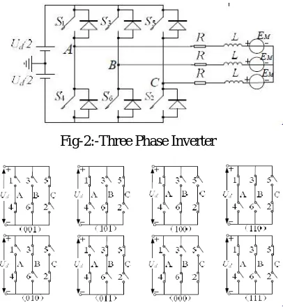
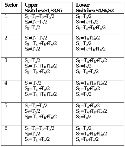
The conventional three-phase inverter is shown in Fig.2, which has eight different operating modes as shown in Fig. 3. Inverter is operated under complementary control. Define the state that upper arm is switch-on while lower arm is switch-off as “1”, otherwise “0”.
Fig-2:-Three Phase Inverter
Fig-3:-Switching states of Three Phase Inverter
SUPPL
DC supply3 Phase Inverter SVPWM
Starting Algorithm based
on stator MMF Regulation
Fundamental voltage space vectors can be expressed as follows:
= (
+
+
) (1)
By substituting corresponding terminal voltage potential under different operating states into (1), eight fundamental vectors can be got, including six non-zero vectors which are U1~6 and two zero vectors which are U0 and U7. The amplitude of six non-zero vectors is 2/3Ud and that of two zero vectors is zero.
A-B-C axis aligns with three-phase stator axis of BLDC motor and the region is divided into six sectors by non-zero voltage space vectors as shown in Fig. 4.
Fig-4:-Switching Vectors and Sectors Switching Time Duration in any Sector,
T =√ . . sin πcosα −cos πsinα (2)
=√ −cosα. sin π+ sinα. cos π (3) T = T−T−T (4)
Table 1:- Times Ta, Tb and T0 for all sectors
Sector Ta Tb To
I Tz.a.sin( − ) Tz.a.sin( ) Tz - Ta - Tb
II Tz.a.sin( − ) Tz.a.sin( − ) Tz - Ta - Tb
III Tz.a.sin( − ) Tz.a.sin( − ) Tz - Ta - Tb
IV Tz.a.sin( − ) Tz.a.sin( − ) Tz - Ta - Tb
V Tz.a.sin( − ) Tz.a.sin( − ) Tz - Ta - Tb
VI Tz.a.sin( 2 − ) Tz.a.sin( − ) Tz - Ta - Tb
The SVPWM is realized based on the following steps:
Step1. Determine Vd, Vq, Vref, and angle (α).
Step2. Determine time duration Ta, Tb, T0.
Table 2:- Switching sequence table for each switch in each leg
Sector Upper
Switches:S1,S3,S5
Lower
Switches:S4,S6,S2
1 S1=Ta+Tb+To/2
S3=Tb+To/2
S5=To/2
S4=To/2
S6=Ta+To/2
S2=Ta+Tb+To/2
2 S1=Ta+To/2
S3= Ta +Tb+To/2
S5=To/2
S4= Tb+To/2
S6=To/2
S2=Ta+Tb+To/2
3 S1=To/2
S3= Ta +Tb+To/2
S5= Tb +To/2
S4= Ta+Tb+To/2
S6=To/2
S2=Ta+To/2
4 S1= To/2
S3= Ta +To/2
S5= Ta +Tb+To/2
S4= Ta+Tb+To/2
S6= Tb+To/2
S2=To/2
5 S1=Tb+To/2
S3=To/2
S5= Ta +Tb+To/2
S4= Ta+To/2
S6= Ta+Tb+To/2
S2=To/2
6 S1=Ta+Tb+To/2
S3=To/2
S5= Ta +To/2
S4=To/2
S6= Ta+Tb+To/2
S2=Tb+To/2
. IV. MODELING OF BLDC MOTOR
A general BLDC motor has three phase stator windings and is driven by an inverter which constitutes of six switches. Fig. 1 shows the equivalent circuit of a Y connection BLDC motor and the inverter topology. Assuming that the stator resistance and inductance of all the windings are equal, the voltage equation of a BLDC motor can be expressed as
=
+
+
+
(5)
where , Vx, ix, and ex(x=a, b, c) denote the terminal voltage, the phase current, and the phase BEMF respectively. R is a stator resistance and L is a stator inductance. Vnis the neutral voltage of a Y connection motor.
The electromagnetic torque equation is given by,
=
(6)
where Tedenotes the torque and ωmis the rotor speed. The equation of motor is
= (Te
−
Tl
−
Bwr) (7)
where B is the damping constant, J is the moment of inertia and Tl is the load torque.
e = sin
θ
rkbwm (8)
e = sin
θ
r
−
kbwm (9)
e = sin
(
θ
r +
)kbwm (10)
wm is the rotor mechanical speed and θr is the rotor electrical position.
Back emf is generated as a function of rotor position by above equations. Table 3 shows the function of rotor position of three phases for different sectors of angles from 0- 360°.
Table 3:-Functions of rotor position based on angle
Theta-elect
Ө(o)
Fa (ө) Fb(ө) Fc(ө)
0-60 1 -1 1- Ө
60-120 1 -3+ Ө -1
120-180 5 - Ө 1 -1
180-240 -1 1 -7+ Ө
240-300 -1 9- Ө 1
300-360 -11+ Ө -1 1
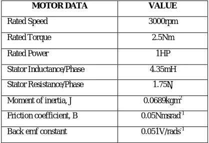
Table 4:- Machine specifications
MOTOR DATA VALUE
Rated Speed 3000rpm
Rated Torque 2.5Nm
Rated Power 1HP
Stator Inductance/Phase 4.35mH
Stator Resistance/Phase 1.75Ω
Moment of inertia, J 0.0689kgm2 Friction coefficient, B 0.05Nmsrad-1
Back emf constant 0.051V/rads-1
V. STATOR MAGNETOMOTIVE FORCE CONTROL
The electromagnetic torque Te is related to stator magnetomotive force Fs, this paper proposes a new strategy to ensure that motor start smoothly by means of regulating stator magnetomotive force before SVPWM algorithm. Detailed analysis on controller of stator magnetomotive force is performed below. As is known that electromagnetic torque of PM motor is proportional to some variables, such as stator magnetomotive force Fs, rotor magnetomotive force Fr and angle between them ψ, which can be expressed as follows:
Tem ᾱ FS . Fr .sinψ (11)
Given that Fr is approximately constant for a PM motor and ψ is supposed to remain unchanged if rotor is synchronous with rotating magnetic field generated by stator windings, we can consider that Tem is directly proportional only to ψ. Hence, employing a closed-loop controller of stator magnetomotive force can reduce torque ripple by controlling electromagnetic torque directly. Combined with SVPWM method, a PI controller of stator magnetomotive force is applied. The PI output is proportional to voltage vector amplitude, which can be input for SVPWM module as reference DC bus voltage Ud.
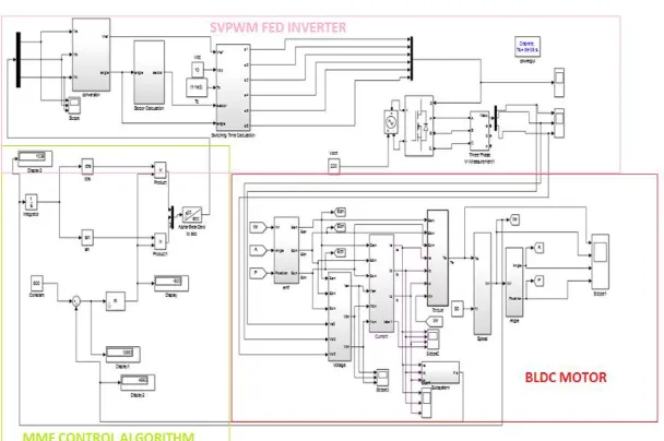
VI. SIMULATION DIAGRAMS & RESULTS
Fig 5:-Simulation diagram of Proposed system.
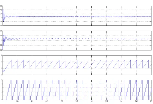
Fig 7:-Torque , Speed ,Angle, Position of BLDC Motor in Open Loop
Fig 8:-Torque , Speed ,Angle, Position of BLDC Motor in Closed Loop
Our main aim of this paper is to reduce the torque ripple and speed ripple in the starting of BLDC Motor . In open-loop control of BLDC Motor Torque ripple is 64% and in closed open-loop control of BLDC Motor Torque ripple is 13% . In open-loop control of BLDC Motor Speed ripple is 50% and in closed loop control of BLDC Motor Speed ripple is 1.7% . So we can conclude that by using closed-loop control we can reduce the torque ripple effectively.
VI.CONCLUSION
A new control strategy combining stator Magnetomotive force control with SVPWM for BLDC motor is done. In Open Loop starting process of BLDC motor pulsation of speed and torque are large. The Torque and Speed ripples for new control strategy is found to be less when compare to Open Loop Control. New control strategy effectively suppress ripples of speed and torque, so its starting performance is greatly improved.
REFERENCES
[1] Sajeev Stanley and Surasmi N L, “Open Loop Control of BLDC Motor Using SVPWM Inverter” in IJAREEIE, Volume 6, Issue 3, March 2017. [2]T.S. Kim, B. G. Park, D. M. Lee, J. S. Ryu, and D. S. Hyun, "A New Approach to Sensorless Control Method for Brushless DC Motors,"International Journal of Control, Automation, and Systems, vol. 6, no. 4, pp. 477-487, August 2008.
[4] Y. S. Lai and Y. K. Lin, “Novel back-EMF detection technique of brushless DC motor drives for wide range control without using current and position sensors,” IEEE Trans. Power Electron., vol. 23, no. 2, pp. 934-940, March 2008.
[5] J. Shao, D. Nolan, and T. Hopkins, “Improved direct back EMF detection for sensorless brushless DC (BLDC) motor drives,” Proc.IEEE APEC, pp. 300-305, 2003.
[6] W. J. Lee and S. Ki Sul, “A new starting method of BLDC Motors without position sensor,” IEEE Trans. Ind. Applicat., vol. 42, no. 6, pp. 1532-1538, Nov./Dec. 2006.
[7] Y.C. Chang and Y.Y. Tzou, “A New Sensorless Starting Method for Brushless DC Motors without Reversing Rotation,” IEEE Trans. . 2007. [8] Z. Anping and W. Jian, “Compare the starting methods of the positino – sensorless BLDC motor,” CCIE Conf., pp. 175-177, June 2010. [9] D. K. Kim, K. W. Lee, B. T. Kim, and B. I. Kwon, “Advanced brushless DC motor drive without position snesor for home appliances,” ICEMS Conf., pp. 707-713, Oct. 2007.
[10] N. Matsui, “Sensorless PM brushless dc motor drives,” IEEE Trans. Ind. Electron., vol.43, no. 2, pp.300-308, Apr.1996.
[11] K S. Ogasawara and H. Akagi, “An approach to position sensorless drive for brushless DC motors,” IEEE Trans. Ind. Appl., vol.27, pp. 8-933, Sept.-Oct. 1991.
[12] A. Dekka, B. Wu, N. R. Zargari, and R. L. Fuentes, "A Space-Vector PWM-Based Voltage-Balancing Approach With Reduced Current Sensors for Modular Multilevel Converter," IEEE Transactions onIndustrial Electronics, vol. 63, pp. 2734-2745, 2016.
[13] A. M. A. S, A. Gopinath, and M. R. Baiju, "A Simple Space Vector PWM Generation Scheme for Any General n-Level Inverter," IEEE Transactions on Industrial Electronics, vol. 56, pp. 1649-1656, 2009.
[14] Soumitra Das and G. Narayanan, Space-Vector-Based Hybrid Pulse width Modulation Techniques for a Three-Level Inverter, IEEE transactions on power electronics, vol. 29, no. 9, september 2014.
[15] Kim Tae-Yeon Y., Chungil Kim and Lyou Joon, “A new sensorless drive scheme for a BLDC motor based on the terminal voltage difference,”