A Review on Current Mirror Circuits
Neha Shukla1, Karan Chandel2
PG Student [VLSI], Dept. of ECE, P.E.C University of Technology, Chandigarh, India1 B. Tech, Dept. of ECE, NIT Hamirpur, Himachal Pradesh, India2
ABSTRACT:. The current Mirror circuits are the most important configuration in field of electronics industry . Mirrors produces the reflection of the object which are placed in fron of them . Similarly the current mirror circuits works in the same way as mirror do . These circuits reflects the currents so that those can be supplied to other sub circuits instead of using more current sources . Constant current source is the heart of the differential amplifiers , hence these circuits are very important in analog VLSI design. These have many more advantages which are highly useful in designing circuits.
KEYWORDS: Cascodes , Wilson , Mirror , high swing
I.INTRODUCTION
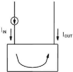
Since the Mirrors are the most important components in our daily life . Inspired form that , a new concept has arisen which produces reflection of current to provide that current as a constant current source to other circuit associated . These circuits have large output impedance and low input resistance which keeps the input & output current source constant in any circuit . These circuit can be split into current – to- voltage and voltage – to-current connected back to back as shown in figure 1.
Figure 1 : Basic Principle of Current Mirror Circuits
There are five main types of current mirror circuits
1. Simplest Current Mirror
2. Cascoded Current Mirror
3. Wilson Current Mirror
4. High Swing Cascode Current Mirror
5. Active Current Mirror
II.VARIOUS CURRENT MIRRORS
If ideal current mirror circuit is to be considered, the it must have gain of -1 but practically there is no such circuit with gain -1. So here is brief description about above mentioned categories of current mirror circuits
Introduction to BGR
has a great advantage of providing constant current source to the circuit . The working of BGR is described below with the help of figure 2 . There are some variations in voltage and current due to temperature variation which is also compensated with BGR.
Figure 2 : Working Principle of BGR
Simplest Current Mirrors
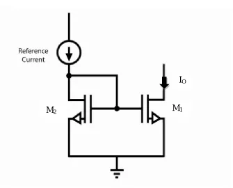
Since current mirrors are used to provide reflection of current in whatever for like scaled or multiplies , to other subcircuits . A typical Simple current cascade is shown below in figure3
Let Ireff is the reference current provide bi reference source. Similarly , IO is the current flowing from M1 . Three cases
arises:
1. I0 > Ireff
2. I0 < Ireff
3. I0 =Ireff
Vgs1 = Vgs2 , the body of the transistor is grounded Then a equation arises;
Ireff=K/2(W/L)2(Vgs2-Vth2)(1+ᴧVds2)...1
Ireff=K/2(W/L)1(Vgs1-Vth1)(1+ᴧVds1)...2
Vth1=Vth2 and ᴧ approaches to 0
Dividing eq1 & eq 2 [IO/Ireff ] = (w/l)2
(w/l)1
1. If W2> W1 , then I0 > Ireff
2. If W2 < W1 , then I0 < Ireff
3. If W2 = W1 , then I0 = Ireff
Figure 3 : Simplest Cascode Circuit
If the current variations are to be observed then it is shown below in figure 4 & 5. The curve is drawn from Ireff =0 to some value , it is assumed that Vds1=Vds2 .
1. For M 2 When Ireff=0 , Vgs1=0 and Vds1 =0=Vds2 , all the transistors are in saturation , current will move till
triode point , after that Vds1 will not be equal to Vds2 shown in figure4.
2. For M1 , When when Ireff=0 , the voltage drop across M1 will be VDD , so the curve will start from vdd as
shown in figure 5
1. FOR M2 TRANSISTORS
Figure 4 : Current Variations M2
I
OM
1M
2Triode point
Safe current cascading
action can take place
Triode
regi
I
0V
ds2Cascode region
2. FOR M1 TRANSISTORS
Figure 5: Current Variations for M1
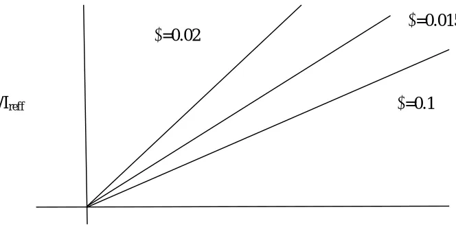
Drawback of Simplest Cascode Current Mirror :
1. If Vds1 is not equal to Vds2 then it is not obvious that IREFF & IO will be defined by ‘W’ and error will
increase as shown in figure 6.
2. Second problems mismatch in Vth due to mismatch in the transistors characteristics.
Figure 6 : Error Variations
Safe current cascading
action can take place
I
0V
ddI
O/I
reffVds2-Vds1
ᴧ
=0.1
ᴧ
=0.015
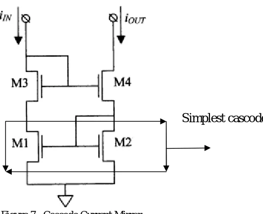
Cascode Current Mirror
Figure 7 : Cascode Current Mirror
To overcome the drawback of simplest diode M3 & M4 transistors are used
Here Vgs2=Ngs4 While Vgs1 = Vgs3. Similar graphs are drawn for M1 , M2 ,M3 & M4.
The transistors M1 & M3 will be in saturation and these both will conduct from zero if Ireff is zero as shown below;
Figure 8 : Current Variations for M1 & M3 Transistors
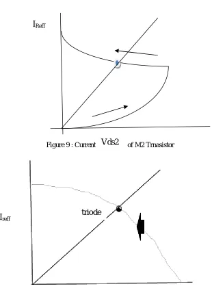
Situation will be different for M2 & M4. , The curve will start from (Vds2-Vds4) and M2 & M4 need not to be in saturation , the current variation is shown in figure 9;
Simplest cascode
I
ReffI
ReffVds1
Vds3
Figure 9 : Current Variations of M2 Trnasistor
Figure 9 : Current variation for M2 & M4
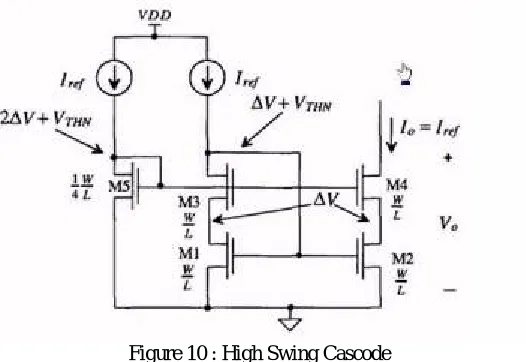
The basic draw back of Cascode morror circuit is that it decreases the output swing , for that high swing cascade are used .
I
ReffVds2
Vds4
I
reffHigh Swing Cascode
Figure 10 : High Swing Cascode Wilson Current Mirror
Because of negative feedback , the drain current is stabilized and series sampling is used for increasing high output impedance.
Active Current Mirrors
III.CONCLUSION
1. From above discussion it is clear that if comparision is made between Cascode mirror circuit & Simplest mirror circuit , minimum voltage required to make cascade action is more in cascode current mirror than in simplest current mirror
2. There is no variations at transistor level in Cascode mirror circuit while there are variations in simplest due to which Vds1 is not equal to Vds2
REFERENCES
[1] S. S. Rajput and S. S. lamar, “A high performance current mirror for low voltage designs”, Proc. APCCASIIEEE, Tiwjin, China, pp. 170-173, Dec2000.
[2] Byung-moo Min and Soo-won Kim, “High performance CMOS current comparator using resistive feedback network”, IEEE Proceedings - Electronic Letters, Pages. 2074-2076, vol.34, Issue.22, 1998.
[3] D.Banks, and C.Toumazou, “Low-power high-speed current comparator design”, IEEE Proceedings - Electronic Letters, vol.44, No.3, 2008 [4] Chun Wei Lin,and Sheng Feng Lin, “ Low Input Impedance Current Comparator Using in Pulse-Width Modulation ”, IEEE Proceedings –
ICCE-2010,Pages.127-130
[5] MULDER,J., WOERD,A.C.; SERDIJN,W.A., and ROERMUND,A.H.M., “High swing cascode MOS current mirror”, Ekec-Iron. Lett., 1996, 32, pp. 1251-1252
[6] Paul.R.Gray, Paul.J.Hurst, Stephen.H.Lewis and Robert.G.Meyer, “Analysis and Design of Analog Integrated Circuits”, by John Wiley & sons, Inc 1984
[7] Voo, T., & Toumazou, C. (1996). Precision temperature stabilised tunable CMOS current-mirror for filter applications. Electronics Letters, 32(2), 105–106
[8] Gupta, M., Aggarwal, P., Singh, P., & Jindal, N. K. (2009). Low voltage current mirrors with enhanced bandwidth. Analog Integrated Circuits and Signal Processing, 59(1), 97–103
[9] Ramirez-Angulo, J., Carvajal, R. G., & Torralba, A. (2004). Low supply voltage high-performance CMOS current mirror with low input and output voltage requirements’. IEEE Transactions on Circuits and Systems II: Express Briefs, 51(3), 124–129
[10] Mulder, J., Van der Woerd, A. C., Serdijn, W. A., & Van Roermund, A. H. M. (1996). High-swing cascode MOS current mirror. Electronics Letters, 32(14), 1251–1252.
BIOGRAPHY
NEHA SHUKLA She is pursuing her MTECH from P.E.C University of Technology and she has also published her papers in ICMTES 2017 , IJARCCE , IJEDR