* Corresponding author: [email protected]
Structure of U-Zr-Mo alloy shell after explosive loading
Dmitry Belyaev*, Alexey Aleksandrov, Yuri Zuyev, Eugene Kozlov*, Igor Svyatov, and Catherine Levi Russian Federal Nuclear Center – Zababakhin All-Russia Research Institute of Technical Physics (RFNC-VNIITF), 456770, Snezhinsk, Chelyabinsk region, RussiaAbstract. This presentation describes investigation of a thick-wall spherical shell 48 mm in diameter from the alloy of uranium with molybdenum and zirconium, which survived after high-intensity explo-sive loading. Investigation was performed in the meridional section of the shell to obtain qualitative da-ta on hardness and microhardness, meda-tallurgical inclusions, damage, and also material microstruc-ture.Structural changes are observed to widely present in the shell material. The localized damage ob-served both at R ≈ 12-14 mm and R ≈ 16-18 mm are the first and second converged spalls, respectively. What is more, in the southern sector the first spall was recompacted with the remelting of a large region of the material in the adjacent layers (region with the enhanced hardness for the first spall). Cracks of the second spall in the northern sector were also recompacted almost completely.
1 Introduction
Investigations into physical properties of a material sub-jected to high-speed intensive loading is of great interest, as far as in addition to fast compression of a material up to high pressures and its adiabatic heating-up, there are extremely high-speed processes of elastic-viscous-plastic deformation, polymorphous and phase transitions, and also shear and spall fractures [1]. Very important sup-plements to techniques that are capable of providing time-resolved data are methods that recover samples for their comprehensive material-science investigation. Spherical explosive recovery experiments have cer-tain advantages compared to the experiments in the plane and cylindrical geometries [2]: (i) the level of created short-term high pressures and temperatures and (ii) min-imal secondary impacts during deceleration and trapping of the recovered samples.
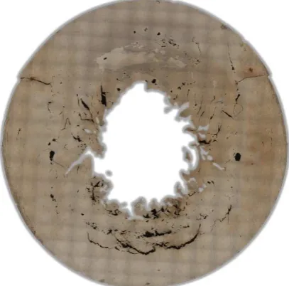
This presentation describes investigation of a thick-wall spherical shell from the alloy of uranium with mo-lybdenum and zirconium, which survived after high-intensity explosive loading. Investigation was performed in the meridional section of the shell (Figure 1) to obtain qualitative data on hardness and microhardness, metal-lurgical inclusions, damage, and also material micro-structure.
The initial shell geometry and the loading mode were similar to those used for the shells described in [3-4]. Systematic comparative study of similar-geometry but different-composition samples allows knowledge on materials properties under high-intensity loading to be increased. The obtained experimental data will be used to verify the models how shear and spall fractures nucle-ate, develop, and recompact in the unalloyed uranium and alloys on its basis.
Fig. 1. Meridional section of the shell. Panoramic picture of the polished section surface used to study the damaged state. Initial diameter was 48 mm.
The stress-deformed state of the shell material was studied through color mapping [5] of measured values of hardness and microhardness, i.e. the method previously used to study similar shells [3-4].
2 Initial state of the shell material
close-to-cubic shape and the size up to 10-12 µm and small ones having the round shape with uneven rugged boundaries and the size of 1-4 µm (Figure 3). Inclusions are ar-ranged mainly along the high-temperature grain bounda-ries. In one section, they are arranged in lines that coin-cide with the axis of the as-received rod blank (Figure 4).
Fig. 2. Microstructure of uranium alloyed with as-received molybdenum and zirconium. Coarse γ-grain with plates having different orientation.
Fig. 3. Nonmetallic inclusions of two types in the material.
Fig. 4. Lined-up inclusions. Orientation of lines coincides with the axis of the as-received rod blank
Initial microhardness of the material measured by the Vickers method under the loading of 100 gram-force was 355-365 kg/mm2.
3 Damage in the meridional section of
the shell
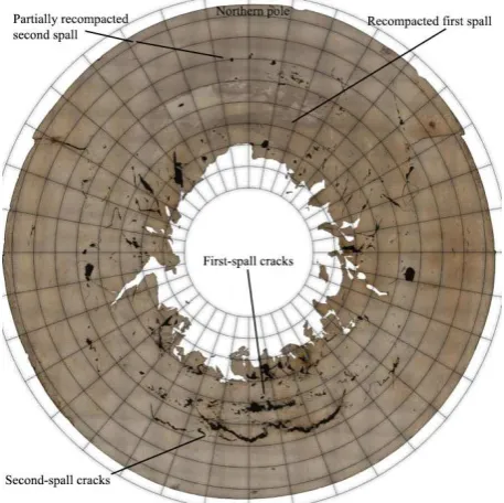
The panoramic picture shows that large cracks localized into spalls of two levels in the southern sector are ob-served at R ≈ 14 mm and R ≈ 16-18 mm (Figure 5). Ap-pearance and shape of spall cracks suggest a relatively high plasticity of the material. At the same radii, the northern sector has a zone with the changed structure of the material and the loading-induced spall cracks arising therein are fully recompacted for the first spall and prac-tically fully recompacted for the second one.
The shear-type cracks are observed to begin at the radius of ~14 mm and terminate in the central cavity and the number of these cracks is observed to be slightly less in the southern sector. These slightly and smoothly curved cracks suggest heavy plastic nonhomogeneous deformation to take place in the materials after cracks formation in the process of loading.
Fig. 5. Panoramic picture of the shell’s meridional section, which is obtained at the polished surface to study damage. Grid has 2 mm×10°cells.
Figure 6 shows the map how damage density ρ is distributed over the surface of the meridional section. This density can be expresses as ρi = 100%×Si/∑Si (where i — is the ordinal number of a crack, Si — is the area of the crack numbered as i). For this map genera-tion, we used no data on macrocracks of the section (sta-tistics excludes cracks with the sectional area exceeding 0.1 mm2). It is obvious from the map that the distribution
Fig. 6. Density of cracks area distribution over the meridional section surface. Dark blue dots show location of cracks centers. Map generation used data on cracks whose sectional area is no more than 0.1 mm2. Grid has 2 mm×10°cells
Figure 7 shows the map how cracks orientation is distributed relative to the radius-vector that goes from the shell center. Red tone color denotes cracks with the spall orientation (angle ψ between the radius-vector and the long axis of cracks is close to 90°). Yellow and green colors show shear-induced cracks for which ψ≈ 45°. Spall-orientation cracks are observed to present in the southern sector at radii that correspond to the first and second spalls (compare to figure 5). Moreover, spall cracks are observed to present at deeper radii of the shell in any direction from the center.
Fig. 7. Map of cracks orientation distribution relative to the radius-vector that goes from the center.
Statistical description of the damage is given in table 1 and graphically given in figure 8. Distribution of the cracks length demonstrates that the share of microcracks is seriously larger compared to that of the large-sized
cracks. The cracks distribution by the orientation angle is observed to have its maximum at the angles wider than 45° and this indicates that among cracks revealed in the shell section the amount of spall cracks is larger com-pared to that of the shear and radial ones. This fact sug-gests a preferred spall mechanism of damaging in the volume of the studied sample.
Fig. 8. Statistical distribution of cracks by length a, and orien-tation angle ψ.
Table 1. Statistical distribution of cracks by area S, length a, and orientation angle ψ (amount 1146 pcs.)
Avg sd Min Median Max S, mm2 0.02 0.18 6.3×10⁻⁴ 1.8×10⁻⁴ 5.01
a, mm 0.26 0.64 0.04 0.11 15.97
ψ, ° 49.62 25.53 0.06 52.04 89.95
4 Structural state of the shell in the
me-ridional section
The structural state of the meridional section has approx-imately annular symmetry (figure 9). Figures 10 — 12 give characteristic microstructure types revealed to pre-sent at different radii and in different zones of the merid-ional section.
a serious plastic deformation and this is confirmed by curved textured bands available in the material.
Large open cracks in the southern sector observed at R ≈ 16-18 mm are interpreted as the second-spall cracks. At the same radii, the northern sector is observed to have multiple cracks recompacted during shell compaction (figure 11). Bands are slightly curved and sometimes their continuation contains discontinuities that indicate incomplete recompaction of spalls during plastic defor-mation of the material. Many bands have local widen-ings filled with the crystallized melt.
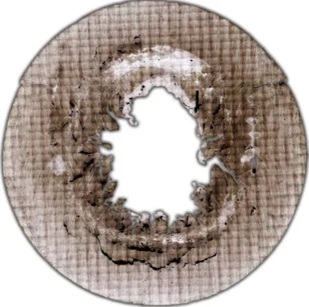
Fig. 9. Panorama of the shell surface after ion-plasma etching was used for microstructure contrast-enhancement.
Fig. 10. Shell material structure that is similar to that in the as-received state. Outer layers of the shell.
Note the zone in the southern sector at radii R ≈ 12-14 mm. This zone contains great many thin practically completely recompacted cracks of spall orientation. This zone shape forms an annular segment and is equidistant to the first spall (figure 9). The above zone and mac-rocracks of the first spall in the southern sector jointly form the first multi-level spall with the inner layers thereof being almost completely recompacted and outer layers – only partially.
The region of the remelted material is observed in the northern sector at the same radii. Energy deposit in this sector, compared to the southern one, was so high that it was sufficient to remelt a large volume of the material and to recompact all formed first-spall cracks.
Shell layers adjacent to the central cavity are ob-served to have a region wherein the material underwent melting and crystallization in the process of explosive loading (figure 12). Throughout the area of the sample section, the structure of melting regions contains colum-nar grains with the growth direction being normal to the region boundary. The size of blocks in this region is less than the size of the grain in the as-received state. In the northern sector, this region has the largest extension.
Fig. 11. Recompaction of cracks with melting traces along edges.
Fig. 12. Melting in shell layers adjacent to the central cavity.
5 Hardness and microhardness
distri-bution
The average value of microhardness increased by ~100 kg/mm2 compared to the initial state.
• Maximum-values zone in the northern sector falls within the region of recompacted first-spall cracks. This zone with the changed material structure in the form of a mushroom having a stipe goes from radii, corresponding to the spall, depthward right down to the central cavity. In both distributions, the zone of maximum values has approximately the same shape;
• Minimum-values zone corresponds to spalls in the southern sector. In the hardness map, this zone is more obvious than in the microhardness map;
• Hardness reduction in layers adjacent to the central cavity along the perimeter, but for the northern sec-tor, falls within the zone of the remelted material close to the central cavity;
• Increase both in hardness and microhardness in the zone of threaded connection sections from the eastern and western sides.
Fig. 13. Map of microhardness distribution on the meridional section of the shell.
Fig. 14. Map of hardness distribution on the meridional section of the shell.
6 Conclusion
Summation of our experimental results draws to several conclusions on the reasons of the observed structural state of the shell.
By analogy with the results obtained when RFNC-VNIITF studied shells from uranium and alloys on its basis [3, 4, 6, 7], this shell demonstrates a similar situa-tion as for the damage formasitua-tion and structural changes. In order to correctly interpret the observed physical changes in the material, it is necessary to know what happened in the shell body under its short-term high-intensity loading. Sequence of events under explosive loading is adequately described in [8].
The first spall is formed in the shell when the con-verging shock wave is first-time reflected from its inter-nal boundary. Then the spall layer begins to move to-wards the center practically by inertia thus spending its kinetic energy for the plastic deformation work and its own heat-up. Attained high temperatures and pressures can lead to the allotropic and phase (melting, evapora-tion) transitions in the shell material.
In shells of brittle materials, while converging the spall layer can be fractured into fragments but according to the shear mechanism. Explosion products have no impact on the separated layer as it is shielded by an un-destroyed part the shell. If thickness of the spherical HE layer used for the shell compaction is rather small, then explosion products quickly release due to free scatter. In this case, impact of explosion products on the re-mainder part of the shell can be rather insufficient and this part would stop in the process of convergence at a certain radius and would fail to “catch up” with the sepa-rated spall layer. If a heavy housing is placed above the HE layer with the gap there between in order to confine scatter of HE layer explosion products then we can en-sure that the main part of the shell would overtake the spall layer and we can trace the character and specifics in the compaction of the material of the shell fractured at the high radius during its convergence to the smaller radius. If the amplitude of the shock-wave arriving at the internal surface of the shell is rather large, then one or even more spalls can be formed in the remainder part of the shell according to the above scheme. Though, blurred fronts of stress-waves, anisotropy, and material damage lead to the situation when spalls coming after the first spall have no distinct localization along the radius [9]. At last stages of the shock-wave loading, the shell gets compacted thus spending its kinetic energy and fi-nally completely stops. From loading till complete cool-down, there is enough time for the low-velocity process-es of heat conductivity, diffusion, recrystallization, and defect annealing to take place.
In the southern sector, only partial recompaction of the first spall is observed in inner layers. Outer layers of the first spall involve different-size cracks. The second spall in the southern sector failed to recompact.
The shell material bears marks of plastic deformation throughout the test meridional section.
Appearance and shape of cracks attest to the fact that the material underwent brittle ductile fracture, i.e. rela-tively short length and round shape of cracks compared to the shape of cracks revealed, say, in the section of a similar shell made from uranium alloyed with iron and germanium [4].
Local reduction of hardness and microhardness is observed in annular zones of the southern and northern sectors at the second-spall radius and distribution maps confirm this.
Multiple cracks going to the internal cavity of the shell are oriented at the angle of ~45° to the radius and this suggests the shear mechanism of the first-spall-layer fragmentation during convergence.
At the microstructural level, changes involve plastic deformation and local remelting when edges of shock-induced discontinuities are welded.
References
1. T. Antoun, L. Seaman, D.R. Curran, G.I. Kanel, S.V. Razorenov, A.V. Utkin, Spall Fracture (New York: Springer-Verlag Inc. 2003)
2. Е.А. Kozlov, B.V. Litvinov, V.К. Orlov, et al.,
Structural and Phase Transformation, as well as Microhardness vs Radius for Spheres of Uranium and two its Alloys after Spherical Explosive Load-ing. Int. Conf. Shock Waves in Condensed Matter, p.31. (July 18 — 22, St.-Petersburg, RUSSIA, Abst. 18-6 1994)
3. D.A. Belyaev, Yu.N. Zouev, E.A. Kozlov, I.V. Podgornova, I.L. Svyatov. Metallographic studies of uranium shells after shock-wave loading using color mapping method, Book of Abstracts for IX International Ural Workshop «Radiation Damage Physics», p.53. (Kyshtym, February 20 — 26 2011)
4. D.A. Belyaev, A.S. Aleksandrov, Yu.N. Zouev, E.A. Kozlov, S.A. Lekomtsev, A.S. Nedosvity, I.L. Svyatov, E.A. Levi. Metallographic examina-tion of meridional secexamina-tion of a shell made from uranium alloyed with iron and germanium after ex-plosive loading. Book of Abstracts for XI Interna-tional Ural Workshop «Radiation Damage Phys-ics», pp. 33 — 34. (Kyshtym, February 23 — March 1, 2015)
5. D.A. Belyaev, Yu.N. Zouev, A.V. Lukin, I.L. Svyatov. Application of the color mapping method in metallographic study of samples after dynamic loading. Factory laboratory. Diagnostics of materials. V. 82, No. 6. pp. 40 — 43 (2016) 6. D.A. Belyaev, Yu.N. Zouev, E.A. Kozlov,
I.L. Svyatov. Spall and shear damages of a shell of U—1.5% Mo alloy under explosive loading. De-formation and fracture of materials. No.2. pp. 26 — 30 (2012)
7. D.A. Belyaev, A.S. Aleksandrov, E.A. Kozlov, Yu.N. Zouev, I.L. Svyatov, E.A. Levi. Structure of thick-walled spherical shell of U-1.5% Mo alloy af-ter explosive loading. In: Proc. 11th International Conference on the Mechanical and Physical Behav-iour of Materials under Dynamic Loading (DYMAT-2015, Lugano, Switzerland, September 7th — 11th 2015)
8. E.A. Kozlov et al., Spall and shear destruction in spherically converging shells out of iron and steel. Measurement of Energy and Residual Defor-mations, J. Deformation and destruction of materi-als (Deformatsiya i razrusheniye materialov), 11, 2 (2008)