* Corresponding author: [email protected]
FPGA-based protein sequence alignment : A review
Mohd. Nazrin Md. Isa 1*, Ku Noor Dhaniah Ku Muhsen1, Dayana Saiful Nurdin1,, Muhammad Imran Ahmad2,, Sohiful Anuar Zainol Murad1, Shaiful Nizam Mohyar1, Azizi Harun1 and Razaidi Hussin1
1School of Microelectronic Engineering, Universiti Malaysia Perlis, Pauh Putra Campus, Perlis, Malaysia
2School of Computer and Communication Engineering, Universiti Malaysia Perlis, Pauh Putra Campus, Perlis, Malaysia
Abstract. Sequence alignment have been optimized using several techniques in order to accelerate the computation time to obtain the optimal score by implementing DP-based algorithm into hardware such as FPGA-based platform. During hardware implementation, there will be performance challenges such as the frequent memory access and highly data dependent in computation process. Therefore, investigation in processing element (PE) configuration where involves more on memory access in load or access the data (substitution matrix, query sequence character) and the PE configuration time will be the main focus in this paper. There are various approaches to enhance the PE configuration performance that have been done in previous works such as by using serial configuration chain and parallel configuration chain i.e. the configuration data will be loaded into each PEs sequentially and simultaneously respectively. Some researchers have proven that the performance using parallel configuration chain has optimized both the configuration time and area.
1. Background
Protein sequence alignment searches for sequence homology between query (unknown sequence) and subject sequence. For the case of pairwise sequence alignment, a query sequence of length n with sequence characters of (
x
1x
2
x
n) and a subject sequence characters of (y
1y
2
y
m)of length m, is The Smith-Waterman algorithm shown in (1), using dynamic programming (DP) to solve the sequence alignment problems in finding the best score as shown in Fig. 1.Fig. 1. The DP illustrate how SW algorithm obtain the final output which is the best score of F(i,j) and form a matrix F of scores [17].
Based on (1), F(i,j) is the similarity score of node at the (i,j) position. The best score is the maximum value among the four possible values based on (1).
0 ) 1 , (
) ,1 (
) , ( ) 1 ,1 ( max ) , (
d j i F
d j i F
y x s j i F
j i F
j i
(1)
Here s(xi,yj) represents the similarity score by residue comparison of x and y sequence which can be obtained from the substitution matrix.
A. Protein Sequence Alignment
In protein sequence alignment, substitution matrix score has been substitute into the equation of DP algorithm for computation process in finding the optimal alignment between two sequences. Substitution matrix is a two dimensional matrix which shows the relationship between each protein residues since the penalty score of substituting a character with another character is different for each residue due to the biology meaning. There are several examples of substitution matrices for protein residue such as the BLOck SUbstitution Matrix (BLOSUM) e.g. BLOSUM50 and BLOSUM62 and Point Accepted Mutation (PAM) e.g. PAM160. The BLOSUM50 substitution matrix is illustrated as in Fig. 2. It has been widely used in aligning biological sequence.
Fig. 2. BLOSUM50 substitution matrix [12].
Commonly, alignment matrix computation involves two stages; the configuration stage and the computation stage. Flow chart in Fig. 3 describes the process flow of filling in an alignment matrix for protein pairwise
* Corresponding author: [email protected]
sequence alignment. The configuration stage involves with access or load data into the PE. One query residue xi will be preloaded into each PE and then the substitution matrix’s column corresponding to the query residue will be loaded in the form of a Look-Up Table (LUT). This initial stage relates mostly with memory accesses. The next stage dealing with arithmetic instructions which is the computation of best match score. There are several challenges on filling in an alignment matrix which consists of frequent memory access and high data dependency during PE configuration. The next section discussed on related works that have been done in order to optimized both configuration time and PE area complexities.
Fig. 3. The flow that shows steps involved in calculating the optimal alignment score by using DP algorithm. The curved edge rectangle represents process involving memory access [23].
2 A Survey of Hardware Implementation and Several Approach of PE Configuration
Reference [10] was among the first in 1990s that used FPGA to accelerate DP algorithm with systolic array. It was reported that they proposed the implementation on SPLASH reconfigurable array which is among the earliest off-the-shelf FPGA-based sequence-edit distance accelerators. In early 2000s, FPGAs has become more favored platform especially for acceleration hardware since the size are become larger and the performance is also almost proportional to the size of the FPGA. Moreover, FPGAs is capable of reprogrammable and consequently leads to implementable of DP algorithms on FPGAs. However, the FPGAs suffering with not have enough hardware resources especially memory bandwidth which is constrain on the memory storage for PE configuration. Thus, configuring the memory access need to be enhanced to achieve faster performance in homology search especially during the initial PE configuration stage.
In 2004, another method that have been considered in FPGA implementation is the modification of the basic
DP algorithm into more simplify algorithm as presented by Dydel and Bala [11] and Gok and Yilmaz [12]. Dydel and Bala claimed that large scale of protein sequence alignment can be done with some modification to the SW algorithm with used the only one row version of an alignment matrix named ‘one row c’ as reference for the next computation during pipelined operation in alignment matrix computation process. This leads to performance speed-up especially when dealing with long sequence length. Commonly systolic array is used as accelerator but this work used different parallelism scheme with 88 copies of PE in one chip. Thus, it can execute the algorithm by processing one fixed query sequence against many different subject sequence in parallel. It leads to better PEs utilization since number of PEs utilized is independent to the sequence length unlike in systolic array. It used five BlockRAMs for each algorithm copy during alignment matrix computation and a full substitution matrix scores were uploaded in one of it. Thus, is used the dedicated limited memory in FPGA which become a bottleneck in hardware implementation using FPGA.
Reference [13] and [14] claimed that they improved the performance of aligning a query sequence with longer length against a database sequence by the used of folded systolic array approach. The alignment matrix computation processed sequentially by multiple passes over the same size of systolic array. The multiple passes concept partitioning the recursive algorithm into smaller alignment due to long length sequence thus the computation can be done without having difficulties in limited hardware resources. This architecture need first-in-first-out (FIFO) to hold the subject sequence and temporarily store the results of each pass during computation stage before fed back into the array for next pass usage as shown in Fig. 4. During configuration stage, each PE is preload with one query sequence and its corresponding substitution matrix column in LUT form. However, this technique suffers with increasing of configuration time and number of LUTs since the alignment process is performed in multiple passes over the linear array i.e. the PE requires different column of substitution matrix for each pass computation.
Fig. 4. The PE loader loads configuring data for each PE with different substitution matrix column corresponding to the query residue, through the serial configuration chain during configuration state [14].
* Corresponding author: [email protected]
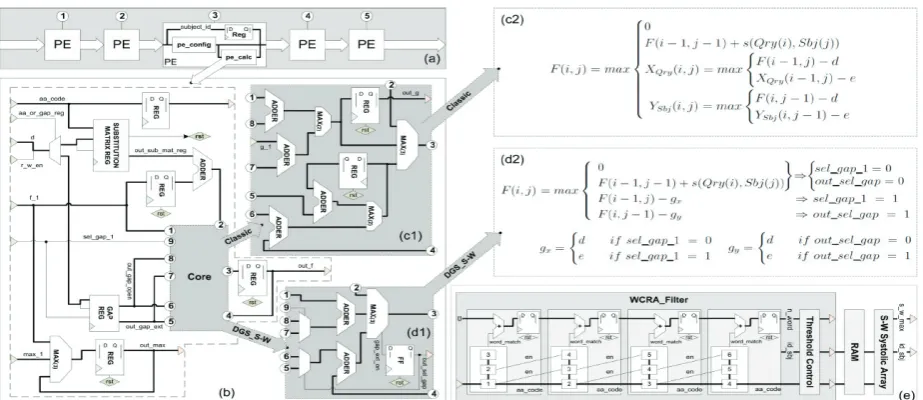
In 2012, Urgese et al. [15] proposed enhanced hardware acceleration by the used of filtering effect and a flexible gap selector which also claimed to be the first to implement. The hardware consists of a Dynamic Gap Selector Smith-Waterman (DGS_S-W) which reduced the computation time compared to the classical solution of SW algorithm, and also a Word Counter Reduced Alphabet Filter (WCRA_Filter) which be able to remove the insignificant residue hence reduced the amino acids residue for repetitive computation of SW in the huge reference database as illustrated in Fig. 5. It stored a column of substitution matrix corresponded to the query sequence in a register in each PE sequentially thus, the PE configuration time is increasing with the number of PEs. Even though the filter managed to reduce the sequence length, it faces the same challenge as sequence alignment using heuristic approach endure. The result showed that it has increasing error which proportionally to the query sequence length due to low sensitivity issue of alphabet filtering approach.
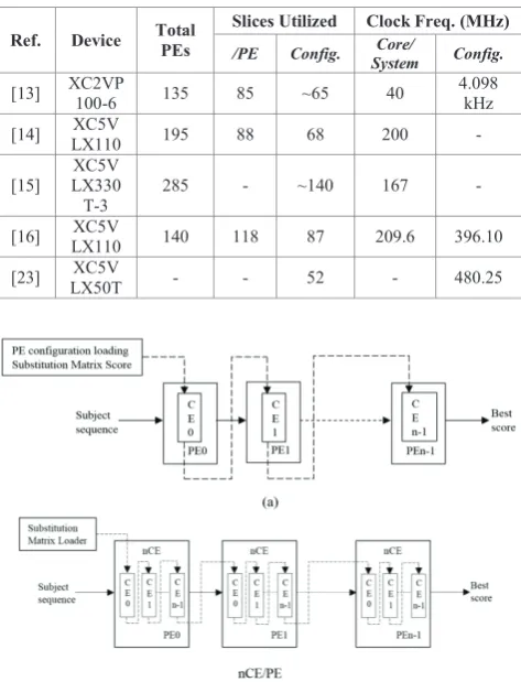
In 2011, Isa et al. [14] proposed the PE design with multiple number of configuration element (CE) holding the desired column of substitution matrix. This architecture allows alignment matrix computation using folded systolic array which is suitable in computation for longer length of query sequence. Thus, number of CEs (nCEs) in each PE depends on the total number of passes (n-pass) or folding factor as shown in Fig. 6. During configuration stage, the CEs is preloaded with the substitution matrix column related to its query residues held by each PEs as shown in Fig.6 by the dotted line. It will be loaded in the form of LUTs. Thus, the alignment computation process can be progressed without the need of reconfiguring the PE with new LUT for the next fold of computation process since the PE loader can update the PE with coefficient needed for each passes in simultaneously. This PE stored the substitution matrix columns using the abundant CLB logic slices, therefore the dependency of the design with the limited memory resources was reduced.
Fig. 6. The PE design consists of multiple configuration elements (nCEs) [14].
Besides, it also allows PE scalability due to the nCEs required in each PE but it suffers with nCE area overheads per PE. However, the CEs is being updated in serially, thus it increases the PE configuration time since it required n-pass in initial configuration stage due to the long sequence length. Consequently, in order to achieve better PE configuration design, the new PE architecture with fixed number of CEs are proposed in 2014 as reported in [16]. It is called the overlap computation and configuration (OCC). This architecture had optimized the logic resources by having only two CEs instead of having nCEs in each PEs. Each PE is used for supplying the substitution matrix for alignment matrix computation by one after another.
Regarding to have folded or n-pass computation with only two CEs, this approach used a well-organized scheduling strategy based on double buffering technique which efficiently organized the CEs to operate one after another through a controller. Both CE works with overlapping operation where one CE will be preloaded with the coefficients needed for the next computation pass while another CE is being used for the current pass of computation. Both of these processes occurred at the same time. The overlapping operation have proven that this architecture have used parallel configuration chain where it updates all the PEs with the desired column of Fig. 5. (a) SW systolic array. (b) PE architecture of SW. (c1) Classic SW core implementation. (c2) Classic SW algorithm.
(d1) DGS_SW core (optimized). (d2) DGS_SW SW algorithm. (e) Complete connection between WCRA_Filter architecture and SW systolic array [15].
* Corresponding author: [email protected]
substitution matrix in simultaneously during the current subsequence pass computation occurs. However, the CEs is being updated in serially during PE configuration thus the configuration time is still independent to the number of CE.
In 2015, a new approach of PE parallel loader have been proposed by the used of parallel configuration chain technique. The parallel loader comprises of several circular buffers (CBs) using shift registers (SRL32). The total number of columns, ncol and rows, nrow of the substitution matrix represents the total number of shift registers within each CBs and the total number of CB respectively as shown in Fig. 7. The ncol and nrow is parameterizable for this loader. The substitution matrix scores are loaded column by column into the circular buffers. After the configuration data completely loaded into the buffers, it keeps on shifting within the buffers to avoid data loses. When the probability scores are ready as an output by the circular buffers, then it is all set to be transmitted to the PEs through a large data bus. The data bus connected to all circular buffers output and broadcast the requested substitution matrix column corresponding to the query sequence resides in each PEs. The loader can be connected to each PEs in parallel and allows the configuration elements to be transferred simultaneously into all the PEs. Hence, the configuration time for this parallel loader is independent to the number of PEs. In PE architecture with folded systolic array which have multiple passes for long length query sequence alignment, this parallel loader can supply the substitution matrix columns required for one fold simultaneously for each PEs without any delay. The configuration elements can be selected by a multiplexer during PE configuration in order to select the required substitution matrix columns corresponding to the query residues within the PEs for a particular fold. Thus, all the PEs can be updated concurrently for each pass of computation during PE configuration stage. Consequently, the parallel loader can reduce the configuration time from tconfig. x (nCE x nPE) to tconfig./(nCEx nPE) due to it is independent to both the number of CE and PE. Moreover, this loader used the FPGA’s LUT instead of using the limited dedicated memory in FPGA. Hence, the parallel loader managed to avoid the bottleneck of using FPGA.
Fig. 7. The PE parallel loader with circular buffers [23].
3 Results and Discussion
This section discusses the FPGA-based implementation performance with varies methods used of PE loader which had been reviewed in previous section. The results from proposed PE architecture which used between serial configuration chain [13]-[15] and parallel configuration chain [16], [23] is summarized in Table 1. Some researchers include the total number of slices utilized for PE configuration in the performance result and some of them only consider the total slice utilization for the core architecture of the PE. Slices is actually the elementary programmable logic block in Xilinx FPGAs. Thus, an estimation results in terms of configuration area has been made for [13] and [15] due to lack of information on the initial configuration performance. A conclusion has been made that most of designs have the same number of slice utilization with ~77% of the total number slices utilized per PE just for the PE configuration elements. Hence, it gives the estimation slices utilized on the PE configuration for [13] is ~65 slices while [15] utilized about ~140 slices. However, the new approach of PE parallel loader from [23] has the least slice utilization.
In terms of the clock frequency or speed performance of the PE configuration, the results from prior works which used the parallel configuration chain technique shown to be faster than the works that used serial configuration chain. Typical core system operating between 100 to 200 MHz. Thus, both [16] and [23] shows that they achieved by ~4 times faster.
Table 1. Performance Comparison Against various FPGA implementation
Ref. Device Total PEs Slices Utilized /PE Config. Clock Freq. (MHz) Core/
System Config.
[13] XC2VP 100-6 135 85 ~65 40 4.098 kHz
[14] LX110 XC5V 195 88 68 200 -
[15] LX330XC5V
T-3 285 - ~140 167 -
[16] LX110 XC5V 140 118 87 209.6 396.10
[23] LX50T XC5V - - 52 - 480.25
* Corresponding author: [email protected] (d)
Fig. 8. Various approach of substitution matrix loader; by serial
configuration chain approach (a) with one CE per PE [15], (b) with multiple CEs per PE [14], and by parallel configuration chain approach (c) with two fixed CEs per PE [16], and (d) single CE per PE whereby all the PE connected in parallel with the loader [23].
Based on PE configuration architecture for the substitution matrix storage during the configuration stage as illustrated in Fig.8, some researcher proposed to store only a column of substitution matrix in a register such as in [15] as shown in Fig.8 (a). Nevertheless, other PE architecture literally that had reported stored the entire substitution matrix score in the restricted memory resources to enable rapid access of the scores as in [13]. On the other hand, work by Isa et al. in [14] and [16] used PE loader by storing a column of substitution matrix in each CE. Though it updates the PEs with required substitution matrix column even for each passes in folded systolic array concurrently, the CEs still updates by serially as shown in Fig.8 (b) and (c). Consequently, it yet takes higher PE configuration time. Hence, another approach of PE loader used parallel configuration chain technique as in [23] is an efficient way to update each PE with a desired column of substitution matrix simultaneously as shown in Fig.8 (d).
4 Conclusion
This paper reviewed PE configuration methods for various pairwise protein sequence alignment architectures. There are two widely used techniques for PE configuration; serial and parallel configurations. Results have shown that, parallel configuration chain technique achieved better configuration speed i.e. ~4 times faster than the PE systolic array core frequency. However, not all PE configuration with parallel configuration technique be able to optimize in terms of area due to design optimization and tradeoff. Nevertheless, the new approach of PE parallel loader has proven that it can be optimized in terms of both area and speed complexities. It managed to perform at 480.25 MHz of clock frequency due to its ability to update all the PEs with the configuration elements simultaneously. Moreover, it also achieved least slice utilization of only 52 slices, which is almost ~2 to 3 times smaller than reported work in literature.
This work was supported by the FRGS under Grant 900300480. Modelling of an Efficient DNA/Protein Sequencer using Hardware Description Language (HDL) for Biomedical Applications.
References
1. D. Lavenier and M. Giraud, Reconfigurable Computing, pp. 157-182 (2005)
2. T. F. Smith and M. S.Waterman, J. Molec. Biol., 147, no. 1, pp. 195–197 (1981)
3. S. B. Needleman and C. D. Wunsch, Journal of Molecular Biology, 48, pp. 443–453 (1970)
4. J. Xianyang, et al., IEEE Transactions on Circuits and Systems II, 54, no. 12, pp. 1077-1081 (2007)
5. K. Dohi, K. Benkrid, C. Ling, T. Hamada, and Y. Shibata, 21st IEEE International Conference on Application-specific Systems Architectures and Processors (ASAP), pp. 29-36 (2010) 6. Y. Munekawa, F. Ino, and K. Hagihara, 8th IEEE International
Conference on BioInformatics and BioEngineering, pp. 1-6, (2008)
7. X. Feng, H. Jin, R. Zheng, L. Zhu, and W. Dai, International Journal of Parallel Programming, pp. 1-22 (2013)
8. W. Liu, B. Schmidt, G. Voss, A. Schroder, and W. Muller-Wittig, 20th IEEE International Parallel and Distributed Processing Symposium, pp. 8, April (2006)
9. L. Hasan, M. Kentie, and Z. Al-Ars, IEEE Annual International Conference, Engineering in Medicine and Biology Society, EMBC, pp. 2442-2446, August (2011)
10. D. T. Hoang, International Workshop on Field Programmable Logic and Applications, Vienna, Austria (1992)
11. S. Dydel and P. Bała, Field Programmable Logic and Application, pp. 23-32 (2004)
12. M. Gök and C. Yılmaz, Computer and Information Sciences– ISCIS pp. 277-285 (2006)
13. K. Benkrid, Y. Liu, and A. S. Benkrid, IEEE Transactions on Very Large Scale Integration (VLSI) Systems, 17, pp. 561-570 (2009)
14. M. N. Isa, K. Benkrid, T. Clayton, C. Ling, and A. T. Erdogan,
NASA/ESA Conference on Adaptive Hardware and Systems (AHS), pp. 344-351 (2011)
15. G. Urgese, M. Graziano, M. Vacca, M. Awais, S. Frache and M. Zamboni, 19th IEEE International Conference, in Electronics, Circuits and Systems (ICECS), pp. 145-148, December (2012) 16. M. N. Isa, M. I. Ahmad, S. A. Z. Murad, R. C. Ismail & K.
Benkrid, Region 10 Symposium, 2014 IEEE, pp. 39-44, April (2014)
17. H. T. Kung, International conference on Management of data (SIGMOD '80), New York, USA (1980)
18. R. J. Lipton and D. Lopresti, Proc. of the Chapel Hill Conference on VLSI,H Fuchs, Ed. Rockville, pp. 363-376 (1985)
19. J. M. Marmolejo-Tejada, V. Trujillo-Olaya, C. P. Renteria-Mejia, and J. Velasco-Medina, 2014 IEEE 5th Latin American Symposium on Circuits and Systems, Santiago, pp. 1-4, February (2014)
20. L. Hasan and Z. Al-Ars, Annual International Conference of the IEEE, Engineering in Medicine and Biology Society, EMBC 2009. pp. 3845–3848 (2009)
21. Z. Nawaz, M. Nadeem, H. van Someren, and K. Bertels,
International Conference on Field-Programmable Technology (FPT), 2010, pp. 454–459 (2010)
A. Pulka and A. Milik, Proceedings of the 18th International Conference, Mixed Design of Integrated Circuits and Systems (MIXDES) 2011, pp. 283–288 (2011)
22. K.N.D. Muhsen, “Design and analysis of an efficient repository system for protein coefficients in systolic array-based architecture by using Xilinx Virtex-5 FPGA,” M.S. thesis, Dept. Microelectronic Eng., Univ. Malaysia Perlis, Perlis, Malaysia, (2015)
![Fig. 1. The DP illustrate how SW algorithm obtain the final output which is the best score of F(i,j) and form a matrix F of scores [17]](https://thumb-us.123doks.com/thumbv2/123dok_us/8125360.1353918/1.595.96.282.473.581/illustrate-algorithm-obtain-final-output-score-matrix-scores.webp)
![Fig. 4. The PE loader loads configuring data for each PE with different substitution matrix column corresponding to the query residue, through the serial configuration chain during configuration state [14]](https://thumb-us.123doks.com/thumbv2/123dok_us/8125360.1353918/2.595.96.265.241.386/configuring-different-substitution-column-corresponding-residue-configuration-configuration.webp)
![Fig. 8. Various approach of substitution matrix loader; by serial configuration chain approach (a) with one CE per PE [15], (b) with multiple CEs per PE [14], and by parallel configuration chain approach (c) with two fixed CEs per PE [16], and (d) single C](https://thumb-us.123doks.com/thumbv2/123dok_us/8125360.1353918/5.595.55.290.64.258/various-substitution-configuration-approach-multiple-parallel-configuration-approach.webp)
