Numerical simulation of gas flow and droplet
motion in a wave-plate eliminator of the
separator-steam-generator system in the
waste-heat-utilisation complex
Valerij Artemov1, Konstantin Minko1,*, Georgij Yankov1, Anton Ptakhin2, Anton Kondratev2 and Oleg Milman2
1National Research University “Moscow Power Engineering Institute”, 111250, Moscow, ul. Krasnokazarmennaya 14
2Scientific Production Company “Turbocon”, 248010, Kaluga, ul. Komsomol’skaya Roshcha 43
Abstract. This paper studied the droplet transport and deposition in the turbulent flow inside a wave-plate eliminator of the waste-heat utilisation complex (WHUC). The Lagrangian discrete particle approach was used to simulate the process of liquid separation from wet steam flow. Two different models for droplet-eddy interaction were tested using data from the available literature. The tested numerical model was used to predict the WHUC performance.
1 Introduction
The droplet transport and deposition in the turbulent flow inside a wave-plate eliminator of the WHUC (Fig. 1) [1] were studied using an Eulerian-Lagrangian computational approach. Flash boiling occurs in the nozzle because of a sharp pressure drop which results in a metastable liquid state. The steam-liquid mixture is sent to the expansion unit and then to the wave-plate eliminator. The temperature and pressure of the water entering the nozzle are tin = 257°C and pin = 10 MPa. The pressure of the steam-liquid mixture leaving the
expansion unit is approximately pout = 1 MPa. This paper presents the result of numerical
simulation of liquid droplet behaviour in the separator. The information about processes in the nozzle and the operating condition at the inlet of the wave-plate eliminator were obtained using the model presented in [2].
2 Mathematical model
There is presently significant number of works devoted to the theoretical and experimental study of two-phase dispersed flow [3]. The Lagrangian discrete particle approach (LDP-approach) was used in this paper to simulate the process of liquid separation from wet- steam flow in the wave-plate eliminator of the WHUC.
Fig. 1. The separator-steam-generator system of a prototype WHUC (sizes in mm): (1) nozzle; (2) expansion unit; (3) wave-plate eliminator.
In the LDP-approach, the continuous-phase flow field is computed using the Reynolds averaged Navier-Stokes equations and discrete-phase droplet motion is obtained from the time integration of Newton’s law. Different modifications of the LDP-approach are available in commercial CFD codes. In this work, the approach realised in the author's CFD code ANES [4] was used. The main features are as follows: droplets have no feedback effect on the carrier gas; there is no heat and mass transfer between the dispersed and continuous phases; there is no droplet-droplet interaction (and, therefore, coalescence); droplets behave as hard spheres; drag is the only force acting on the droplets; there is no droplet-film interaction at the wall; only one droplet-wall interaction is considered—the liquid droplets trapped by the wall.
The dispersion of particles due to turbulence in the continuous phase is simulated using a stochastic tracking model [5]. The instantaneous continuous phase velocity is given by
( , , , )x y z t ( , , )x y z ( )t
u u u , (1)
where u( , , )x y z – the mean fluid phase velocity which was obtained using one of the models to describe the turbulent transport of momentum (the k-ω model [6] was used in this paper), u(t) – the fluctuating continuously phase velocity. Many droplets should be injected in the domain until stationary statistics are achieved.
Components of the fluctuating velocity u(t) are step functions of time. The basic parameters of the function are amplitude ut and step width tt. Two different models were tested. In the first model, all the values calculated at the start of the droplet-eddy interaction used characteristics of the flow at the particle location and remained constant during the droplet-eddy interaction (model №1). In the second model, all the necessary parameters of the droplet-eddy interaction (amplitude of the function and the eddy interaction time) were “modified” by the local flow characteristics at the particle location (model №2).
Amplitude of the fluctuating continuous-phase velocity is calculated by the equation
t,i i *, * 23k, 1,2,3
u u u i , (2)
where k – turbulent kinetic energy, Λi – a random number drawn from a normal probability
distribution with zero mean and standard deviation equal to unit.
In the model №1, the characteristic scale of fluctuation u*and Λi was calculated at the
start of the particle-eddy interaction and remained constant. In the model №2, Λi remained
constant, but u* was updated using k at the droplet location.
The droplet is assumed to interact with the eddy over the smaller (ti) of the two
characteristic times:
1) tlife – the turbulent eddy lifetime,
2) tcross – the eddy crossing time.
The eddy lifetime is given by equation
2
eddy TEk
t С
, (3)
The different value of CTE is used in the literature. The most commonly used are the
following equations 3/4 3 2 2 TE
С С or 2 3 1/2
2
TE
С С , (4)
which correspond to CTE from 0.1 to 0.18 (C equals 0.09). In this work, constant CTE was
equal to 0.15. For the k-ω models, substitute C k is used.
In the model №1, the interaction time ti is calculated at the start of the droplet-eddy
interaction and time before the end of droplet interaction with the current eddy is set at
tend = ti. This time is reduced by time step tend = tend – t at each integration time step. At tend = 0, characteristics of the new eddy are calculated. In our model (model №2), time before the end of particle interaction with the current eddy is modified at each time step:
,
, ,
, t new end new end old
t old t t t t
, (5)
where tt new, ,tt old, – droplet-eddy interaction time, which are calculated using
characteristics of the flow at the new and old droplet locations.
3 Validation of mathematical model
The validation analyses are performed through comparison with available experimental data on removal efficiencies of the wave-plate eliminator [7]. Fig. 2 shows comparison results of calculation and experimental data [7].
Fig. 2. Comparison between the predicted droplet-removal efficiency E and the experimental data of Ghetti [7] at gas velocities equal to 3 m/s. 1 – experimental data [7], 2 – model №1, 3 – model №2, 4
– without turbulence dispersion.
The calculation results show that the experimental dependence of the efficiency of the separator (the relation of liquid weight at the outlet and at the inlet) from the particle
diameter (a particle diameter at which 95% of particles were trapped at the wall) can be determined without using a turbulent dispersion-particles model. For example, the experimental value of the cut-off diameter for the bulk velocity of continuous-phase flow equals 3 m/s is 8.5 μm, and the value of this parameter is calculated without considering the turbulent dispersion equals to 9 μm.
4 Problem statements and results
The wave-plate eliminator of the WHUC is a cylindrical channel with an inner diameter of
Dsep = 85 mm, in which several zig-zag plates are installed. At the inlet, wet steam has a flow rate of G0 = 0.317 kg/s and a vapor mass fraction of x = 0.139 at pout = 1044 kPa (it corresponds to tin = 257 °C and pin = 10 MPa at the inlet of WHUC. For details see [2]).
The geometry of the typical element is shown in Fig.3 and the dimensions of the channel are given in Table 1. Two designs are considered: a separator without hooks and a separator with hooks. The mean velocity at the inlet of the typical element of the wave-plate eliminator equals 1.5 m/s.
Fig. 3. Scheme of the typical element of a wave-plate eliminator of the WHUC.
Table 1. The dimensions of the channel.
H, mm , O , mm Hh, mm Wh, mm
9 117 19 0/4 0/4
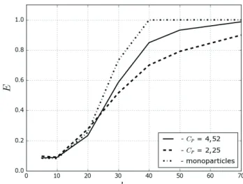
The first series of calculations has been devoted to assessing the impact of droplet-size-distribution parameters on the separation efficiency of the separator without hooks. A Rosin–Rammler model [8] for the particle-size-distribution analysis was used. Three cases were tested: the constants in the Rosi-Rammler models were equal to 2.25 and 4.52 and the case of monodisperse particles. Fig. 4 shows the calculation results. It can be noted that narrowing of the droplet-diameter-distribution function results in an increasing separation efficiency.
diameter (a particle diameter at which 95% of particles were trapped at the wall) can be determined without using a turbulent dispersion-particles model. For example, the experimental value of the cut-off diameter for the bulk velocity of continuous-phase flow equals 3 m/s is 8.5 μm, and the value of this parameter is calculated without considering the turbulent dispersion equals to 9 μm.
4 Problem statements and results
The wave-plate eliminator of the WHUC is a cylindrical channel with an inner diameter of
Dsep = 85 mm, in which several zig-zag plates are installed. At the inlet, wet steam has a flow rate of G0 = 0.317 kg/s and a vapor mass fraction of x = 0.139 at pout = 1044 kPa (it corresponds to tin = 257 °C and pin = 10 MPa at the inlet of WHUC. For details see [2]).
The geometry of the typical element is shown in Fig.3 and the dimensions of the channel are given in Table 1. Two designs are considered: a separator without hooks and a separator with hooks. The mean velocity at the inlet of the typical element of the wave-plate eliminator equals 1.5 m/s.
Fig. 3. Scheme of the typical element of a wave-plate eliminator of the WHUC.
Table 1. The dimensions of the channel.
H, mm , O , mm Hh, mm Wh, mm
9 117 19 0/4 0/4
The first series of calculations has been devoted to assessing the impact of droplet-size-distribution parameters on the separation efficiency of the separator without hooks. A Rosin–Rammler model [8] for the particle-size-distribution analysis was used. Three cases were tested: the constants in the Rosi-Rammler models were equal to 2.25 and 4.52 and the case of monodisperse particles. Fig. 4 shows the calculation results. It can be noted that narrowing of the droplet-diameter-distribution function results in an increasing separation efficiency.
Fig. 4. Effect of particle-size distribution on the separation efficiency of the separation without hooks.
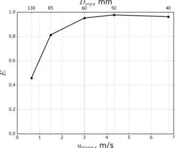
Fig. 5 shows the influence of the mean velocity on the separation efficiency at a fixed value of a mean particle diameter of d32 = 40 μm. Its value was estimated using nozzle
parameters and equations from [9]. The constant in the Rosi-Rammler model was equal to 4.52.
Fig. 5. Effect of mean velocity umean on separation efficiency.
The next series of calculations was performed for various parameters at the inlet of the WHUC nozzle. Table 2 shows the results of the calculation.
Table 2. Influence of inlet parameters of the WHUC. pin, MPa tin, OC G0, g/s x d32, μm E
10 257 317 0.139 40 0.81 10 220 372 0.034 58 0.72 10 300 214 0.259 37 0.81 15 257 442 0.059 47 0.77
For the basic WHUC parameters (pin = 10 MPa, tin = 257 OC), the effectiveness of
particle separation for a separator with hooks increases to 99.6% from 81.3%.
Financial support was provided by the Russian Ministry of Education and Science (contract 14.579.21.0031 with ZAO NPVP Turbokon, identifier RFMEFI57914X0031, 2014) and the Council for Grants of the President of the Russian Federation (MK-6236.2016.8 grant).
References
1. V. A. Fedorov, O. O. Mil’man, D. V. Fedorov, A. M. Trinoga, Energy Saving Technology of Electrical Energy Production at Natural Gas Swapping through Pipeline System (Mos. Gos. Tekhn. Univ., Moscow, 2011)
2. V. I. Artemov, K. B.Minko, G. G. Yan’kov, Therm. Eng., 62, 897 (2015)
3. E.P. Volkov, Modelling of processes of combustion and pyrolysis of solid fuel (ID MEI, Moscow, 2014)
4. URL: http://www.anes.ch12655.tmweb.ru/
5. A. D. Gosman, E. Ioannides, J. Energy, 7, 482 (1981) 6. D. C. Wilcox, AIAA J., 46, 2823 (2008)
7. S. Ghetti, Investigation of Entrainment Phenomena In Inertial Separators (University of Pisa, Pisa, Italy, 2003)
8. P. Gonzalez-Tello, F. Camacho, J. Vicaria, P. Gonzalez, Powder Technol, 186, 278 (2008)

![Fig. 2. Ghetti [7] at gas velocities equal to 3 m/s. 1 – experimental data [7], 2 – – without turbulence dispersion](https://thumb-us.123doks.com/thumbv2/123dok_us/8126667.1354185/3.482.149.322.448.581/fig-ghetti-velocities-equal-experimental-data-turbulence-dispersion.webp)