Power Factor Correction of Three Phase
Rectifier with Interleaved Boost Converter
Mukesh kumar1, Prof. Gautam Kumar Panda2, Prof. Pradip Kumar Saha3
PG Scholar, Department of EE, Jalpaiguri Government Engineering College, Jalpaiguri, West Bengal, India1
HOD and Professor, Department of EE, Jalpaiguri Government Engineering College, Jalpaiguri, West Bengal, India2
Professor, Department of EE, Jalpaiguri Government Engineering College, Jalpaiguri, West Bengal, India 3
ABSTRACT: This paper proposes a method of improving the power factor of a three phase rectifier by using a interleaved boost Converter with Power Factor Correction Controller. When compared to Power Factor Correction and THD minimizations of three phase rectifier with single phase rectifier , Power Factor Correction of three phase rectifier with interleaved boost converter Method is good because here THD is very low . Average Current Control technique has been discussed in this paper. Modelling of the PFC Controller using MATLAB/ Simulink is carried out and the results are verified..
KEYWORDS:Three phase uncontrolled rectifier , Interleaved boost converter, Power Factor Correction, Average Current
Control, MATLAB/Simulink.
I.INTRODUCTION
Single phase rectifier with Power Factor Correction (PFC) has been discussed in many papers [1-5]. But coming to the practical case three phase rectifiers are commonly used for high power applications. Power factor correction is becoming more important nowadays, as we are more concerned about the reduction of harmonic components in the supply side. Power Factor Correction can be of two types: Active or Passive [6]. Passive power factor correction involves the use of linear elements like inductors and capacitors to improve the power factor and minimize harmonic components in the power supply. Passive power factor correction for high power applications requires large inductors and capacitors. So, Active power factor correction is used in high power applications. In active power factor correction methods, the input current is forced to follow the input voltage, so the ratio between voltage and current will be maintained constant and the power factor will be unity, whole circuit emulates as a simple resistor by the power supply [7]. When the ratio between voltage and current deviates from the constant, results in phase displacement ,harmonic distortion or both in the power supply, and deteriorate the power factor [8].
Power factor is defined as the ratio of real input power to the RMS value voltage and current of the load or power factor corrector input.Phase displacement is the measure of reactance of the input impedance of the active power factor corrector. Reactance either in inductive or capacitive form will cause phase displacement of input current waveform with respect to input voltage waveform. Harmonic distortion is the measure of the non-linearity of the input impedance ofthe active power factor corrector. Distortion increases the RMS value of current without increasing total powerbeing drawn. A non-linear load has a poor power factor because the total power delivered is less compared to RMSvalue of current. When harmonic distortion alone is considered, power factor deteriorates to 0.999 for 3% of Total
Harmonic Distortion (THD) .
II. ACTIVE POWER FACTOR CORRECTION
control has a low gain and wide bandwidth. So, by using average current control technique, a better power factor can be achieved and this technique also allows a better input current waveform .
III.AVERAGE CURRENT CONTROL METHOD
.
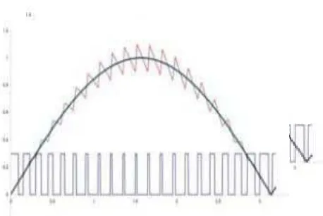
Fig. 2. Average Current Control Technique
Fig. 3. Switch waveforms ith input current waveform
IV.IINTERLEAVED BOOST CONVERTER
Fig.4 interleaved boost converter
A two-limb parallel connected conventional boost converter is shown in Fig.4 this is typically called an interleaved boost converter. This converter is used to improve power factor For a step-up application, an equivalent interleaved boost converter offers several advantages over a conventional boost converter; such as a lower current ripple on the input and output stages. Therefore, there is there is the opportunity to minimise the output capacitor filter that is often quite large in the conventional boost . In addition, it effectively increases the switching frequency without increasing the switches losses. Furthermore, it provides a fast transient response to load changes and improves power handling capabilities. A higher efficiency may be realized by splitting the input current into two paths, substantially
reducing i2R losses and inductor AC losses. This also gives lowstresses on components due to the current split which increases the power processing capability [9]. However, using an interleaved converter increases the number of power handling components and circuit complexity which may lead to an increase in cost. However, in renewable energy systems, long-term improved power generation can help to offset this disadvantage [9]. The topology of the interleaved boost converter consists of two limbs operating at 180 degrees out of phase from each other. Typically, each branch operates in the same fashion as a conventional boost converter previously described in Chapter four. When S1 turns on, the current ramps up in L1 with a slope depending on the input voltage storing energy in L1, D1 is off during this time since the output voltage is greater than the input voltage. When S2 turns off, the L2 inductor delivers part of its stored energy to output capacitor and the load, the current in L2 ramps down with a slope dependent on the difference between the input and output voltage. One half of a switching period later, S2 also turns on, completing the same cycle of events
V. RESULT AND DISCUSSION
The MATLAB Simulink model of interleaved boost PFC converter average current mode control by PI controller is
Fig;5 Simulation block diagram of three phase rectifier with interleaved boost converter
The output voltage waveform is given below as shown in fig 6
Fig;6 output wave forms of interleaved boost converter
The output current waveforms and inductor current waveforms IL1and IL2 is given below respectively as shown in fig:7
The active power and reactive power waveforms is given below as shown in figure 8
Fig;8 Active power and reactive power waveforms
Active power= 1000watt Reactive power = 130 VAR
Power factor= 0.99
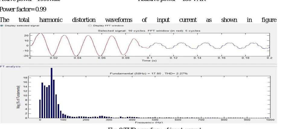
The total harmonic distortion waveforms of input current as shown in figure 9
Fig; 9 THD waveform of input current
The THD of input current is 2.37% which is very low in comparison when we use single phase rectifier [1]
VI.CONCLUSION
REFERENCES
[1]Mukesh kumar,P.k saha and G.k panda,”Comparative Study Of Power Factor Correction And THD Minimization Using Boost Converter And Interleaved Boost Converter Using PI Controller,” in IIAREEIE vol.4, issue 1 2015, pp150-158
[2]K. K. Sen and A. E. Emanuel, “Unity power factor single phase power conditioning,” in Proc. IEEE Power Electron. Spec. Conf. (PESC), 1987, pp. 516–524. [3]F. C. Lee, M. M. Jovanovic, and D. Borojevic, “Analysis and design of power factor correction circuits,” in Proc. Virginia Power Electron. Ctr.(VPEC) Sem., 1996 [4]. M. Zhang, Y. Jiang, Fred C. Lee, “Single phase three-level Boost power factor correction converter,” IEEE Applied Power Electronics Conference, 1995,
pp. 434- 439.
[5]. Milan M. Jovanovic, Fred C. Lac,”Single Phase Three Level Boost PFC Converter”, IEEE, 1995, pp434-439. [6]. Keith H. Billings, "Switch Mode Power Supply Handbook”, McGraw-Hill, New York,1999.
[7]. S. Hsu, A. Brown, L. Rensink, R.D. Middlebrook, “Modelling and Analysis of Switching DC-to-DC Converters in Constant Frequency Current Programmed Mode, “IEEE PESC Proceedings, 1979
[8]. L. H. Dixon, Average Current Mode Control of Switching Power Supplies, Unitrode PowerSupply Design Seminar Manual SEM700, 1990
[9]. L. H. Dixon,” High Power Factor Switching Preregulator Design Optimization”, UnitrodePower Supply Design Seminar Manual SEM800, 1991
[10]. L. Rossetto, G. Spiazzi, P. Tenti, “Control techniques for power factor correction converters”, Proc. of Power Electronics Motion Control (PEMC), September 1994, 1310-1318.
[11]. C. Zhou, M. Jovanovic, "Design Trade-offs in Continuous Current-mode Controlled Boost Power-Factor Correction Circuits'," HFPC conf. proc., 1992, pp. 209-220.
[12]. C. Silva, "Power Factor Correction with the UC3854", Application Note, Unitrode Integrated Circuit. [13]. Simon Ang, Alejandro Oliva, ”Power witching Converters”, Taylor and Francis, Baca Raton,2005.
[14]. P. Mattavelli, L. Rossetto, G. Spiazzi, P. Tenti, "Small-signal analysis of DC-DC converters with sliding mode control," Proc. of Applied Power Electronics Conf. (APEC), Dallas, March 1995, p.153-159. IEEE Transaction on Power Electronics, vol.12, n.1, January, 1997, pp.96-102.
[15].Middlebrook, R. D., and Slobodan Cuk, Advances in Switched-Mode Power Conversion, Volumes I and II, 2nd Edition, TESLAco, 1983.
[16]. G. Spiazzi, P. Mattavelli, L. Rossetto, L. Malesani, "Application of Sliding Mode Control to Switch-Mode Power Supplies," Journal of Circuits, Systems and Computers (JCSC), Vol. 5, No. 3, September 1995, pp.337-354
[17]. IEC 61000-3-4, “Electromagnetic Compatibility (EMC) – Part 3-4: Limitation of Emission of Harmonic Current in Low-Voltage Power Supply Systems for Equipment with Rated Current Greater Than 16A,” First Edition, 1998.
[18] IEEE Standard 519, “IEEE Recommended Practices and Requirements for Harmonic Control in Electrical Power Systems,” 1993.
[19] M. Tognoli and A. C. Rufer, “A DSP based control for a symmetrical three-phase two-switch PFC-power supply for variable output voltage,” in IEEE PESC’96.
[20] T. J. Omedi and R. Barlik, “Three-phase AC-DC unidirectional PWM rectifier topologies-selected properties and critical evaluation,” in IEEE ISIE’96, pp. 784–789.
[21] M. S. Dawande, V. R. Kanetkar, and G. K. Dubey, “Three-phase switch mode rectifier with hysteresis current control,” IEEE Trans. Power Electron., vol. 11, pp. 466–471, May 1996..
[22] J. C. Salmon, “Operating a three-phase diode rectifier with a low-input current distortion using a series connected dual boost converter,” IEEETrans. Power Electron. vol. 11, pp
BIOGRAPHY
Mukesh kumar was born in West Bengal, India on february 06,1991He received his B.Tech degree in Electrical Engineering from Gurunanak institute of technology kolkata, West Bengal in 2013,currently he is doing M.Tech degree in Power Electronics and Drives from Jalpaiguri Govt.Engineering College, Jalpaiguri, West Bengal