ISSN 2348 – 7968
Performance Analysis of Dual inverter for PMSM using
Fuzzy Logic Controller
S.JananiP
1
P
,PPR.PrakashP
2
P
1
P
PG Scholar, Department of Electrical and Electronics Engineering, Vivekanandha institute of Engineering and technology for Women, Tiruchengode, Namakkal District-637205.
Email id: [email protected]
P
2
P
Assistant Professor, Department of Electrical and Electronics Engineering,Vivekanandha institute of Engineering and technology for Women, Tiruchengode, Namakkal District-637205.
Email id: [email protected]
Abstract:
PMSM motor drives fed by dual inverter is purposely designed to reduced size and cost with respect to single motor drives fed by dual inverter. Previous researches on dual motor drives only focus on the modulation and the averaging techniques. Only a few of them, study the performance of the drives based on different speed controller other than Proportional and Integrator (PI) controller. This paper presents a detailed comparative study on fuzzy rule-base in Fuzzy Logic speed Controller (FLC) for Dual Permanent Magnet Synchronous Motor (PMSM) drives. Two fuzzy speed controllers which are standard and simplified fuzzy speed controllers are designed and the results are compared and evaluated. The standard fuzzy controller consists of 49 rules while the proposed controller consists of 9 rules determined by selecting the most dominant rules only. Both designs are compared for wide range of speed and the robustness of both controllers over load disturbance changes is tested to demonstrate the effectiveness of the simplified/reduced rule base. The developed Fuzzy Logic model has the ability to learn instantaneously and adapt its own controller parameter based on disturbances with minimum steady state error, overshoot and rise time of the output voltage.Keywords:
Dual Permanent MagnetSynchronous Motor, Dual inverter, Fuzzy Logic Controller.
I. INTRODUCTION
The Permanent Magnet Synchronous Motors are widely used in many industrial production systems and electric vehicle system due to their distinctive advantages such as compactness, high efficiency, high power density and wide constant power region. Conventionally PI (Proportional-Integral) and PID (Proportional-Integral-Derivative) speed controllers are used to attain the desired speed operation. But PI and PID controllers are very sensitive to parameter variations, thus there is a ripple in the output current. Recently, because of the environmental problem and soaring of the fuel price, electric motor systems are adopted to the many kinds of traction applications such as train and vehicle which were traditionally driven by internal combustion engine (ICE) or external combustion engine (ECE). In addition, because efficiency of the electric traction system is higher than that of ICE, electric traction vehicles have higher mileage than the ICE vehicles. It is expected that efficiency of the future hybrid electric vehicle (HEV) and electric vehicle (EV) becomes higher than the current level thanks to the Improvements of the inverter topology, switching devices, and motor design technologies. AC motors, permanent magnet synchronous motors (PMSMs), and induction motors, are generally used as traction motor for HEV due to their high efficiency although complex control technique is required. Among the ac motors,
PMSMs are mostly used in HEV because of their high efficiency and compactness. Especially, Interior Permanent Magnet Synchronous Motor 2(IPMSM) is suitable for HEV application due to its reluctance torques in field weakening region. Because the required Operating region of HEV motor is much wider than that of other applications, the reluctance torque and wide field weakening characteristic make IPMSM adopted for traction motor of EV. For the first problems although having various controller to improve the speed response but in proposed system FUZZY controller is used. The high efficiency of PMSM Mainly comes from its inherent rotor flux from permanent magnet, whereas other motors need the rotor current for generating the rotor flux. Thanks to this rotor flux, efficiency below the rated speed is higher than other motors and the power factor of the PMSM is also higher than that of other machines. However, this constant rotor flux generates high back-electro motive force (back-EMF) in the high speed region. Because output voltage of the inverter should be controlled under the available range, field weakening control is necessary for the high speed operation [1]–[8]. The negative d-axis current reduces back-EMF and lowers the required voltage. Thus, system can be maintained in the stable operation. Although IPMSM shows higher efficiency than that of other PMSMs in high speed region, it is true that field weakening current restricts output torque and drops the efficiency. By these reasons, high dc-link voltage is required to reduce the field weakening current and secure the high speed operation of HEV [2]. Recently, fuzzy inference system (FIS) is widely used because of its good performance, in cases when the system or process is complicated and classical method cannot work well. Additionally, fuzzy system formulates human knowledge in systematic manner and puts them into engineering systems. But there is a problem associated with FIS, which is the time consuming process to tune the parameters
of FIS relying on human knowledge by trial and error. So, there has been recently a surge of interest to combine neural network and FIS because of its both advantages of fuzzy inference systems and artificial neural networks [3].
II.BLOCK DIAGRAM DESCRIPTION
OF BLDC MOTOR DRIVE
Permanent Magnet Synchronous motor has become the fastest growing and most promising industrial application of a new motor. It contains simple structure, reliable, easy maintenance. It has also contains good mechanical properties and speed performance that DC motor and also having small size, speed, reliability, currently it has been used more widely in high demand in the electric drive system. A PMSM motor when fed by a diode bridge rectifier (DBR) with a high value of dc link capacitor draws peaky current which can lead to a THD of supply current of the order of 65% and power factor as low as 0.8 . Hence, a DBR followed by a power factor corrected (PFC) converter is utilized for improving the power quality at ac mains. Many topologies of the single-stage PFC converter are reported in the literature which has gained importance because of high efficiency as compared to two-stage PFC converters due to low component count and a single switch for dc link voltage control and PFC operation. The choice of mode of operation of a PFC converter is a critical issue because it directly affects the cost and rating of the components used in the PFC converter. A block diagram of Performance analysis of dual inverter for PMSM using fuzzy logic controller is shown in figure 1.
Fig.1.Block Diagram for PMSM drive speed control
Fig. 1 shows the proposed block diagram of performance analysis of dual inverter fed PMSM using FLC. The DC input supply is directly given to the inverter and its converts DC into AC power. The AC input is given to the PM Synchronous motor Then the voltage and the speed of PMSM is given to the fuzzy controller and processed. The output signal from fuzzy controller is given to selective harmonics elimination PWM block which generates gate pulses for the dual inverter. Thus by adjusting the firing angle the speed of PMSM can be controlled.
2.1 Permanent Magnet Synchronous
Motor drive
The development of high-quality permanent magnet materials into commercial production has encouraged several manufacturers to launch various permanent magnet synchronous machines (PMSM) into the market. Permanent magnet synchronous machines have been applied to servo drives for a long time already, and nowadays, there are quite large permanent magnet synchronous machines also in industrial use. In wind mill generators, the development has currently been in the direction of permanent magnet machines. In principle, vector control is required for controlling the PMSM.
The power density of permanent magnet synchronous motor is higher than one of induction motor with the same ratings due to the no stator power dedicated to the magnetic field protection. The basic
differences to the control Principles of other AC motors are due to the magnetic properties of permanent magnets, and particularly to the fact that the permanent magnet material is a part of the magnetic circuit of the machine, and therefore has a significant influence on its reluctance. The relative permeability of permanent magnet materials μr is close to one, and therefore the effective direct air gap of the PMSM often becomes very large. There by also the inductances of the machine particularly in machines in which the magnets are located on the rotor surface usually remain rather low. Another difference is that the direct synchronous inductance, when employing embedded magnets, can be less than the quadrature value, while the ratio is the opposite in a separately excited salient-pole synchronous machine.
The rotor poles are so shaped that the voltage induced in a stator phase has a sinusoidal waveform. As we know, the rotor is made up of permanent magnet. Usually ferrite magnets are employed. Rare earth (cobalt-samarium) magnets, although expensive, are sometimes used to reduce the volume and weight of the motor. Many permanent magnet synchronous motors may be physically cylindrical but electrically the permanent magnet is equivalent to a salient pole structure. Actually, the permanent magnet poles are inherently salient type. Some of the rotors of permanent magnet synchronous motor have the magnets directly facing the air gap.
The PMSM rotate because of the magnetic attraction between the rotor and the stator poles. When the rotor poles are facing stator poles of the opposite polarity, a strong magnetic attraction is set up between them. The mutual attraction locks the rotor and the stator poles together and the rotor is literally yanked into step with the revolving stator magnetic field. At no load conditions, rotor poles are directly opposite to the stator poles and their axes coincide. At load conditions the rotor poles lag behind the stator poles, but the rotor continues to turn at synchronous speed,
the mechanical angle between the poles increases progressively as we increase the load. The permanent magnet synchronous motor is a rotating electric machine in which the stator is a classic three phase stator and employing permanent magnets in rotor. In this motor, the slip ring and field windings are absent. The motor is driven by sine wave voltage coupled with the given rotor position. The stator flux together with the rotor flux which is generated by a rotor magnet defines the torque and thus speeds of the motor.
2.2 Dual Inverter
Inverter is referred as a circuit that operates from a stiff dc source and generates ac output. If the input dc is a voltage source, the inverter is called a voltage source inverter (VSI). A basic three-phase inverter consists of three single-phase inverter switches each connected to one of the three load terminals. For the most basic control scheme, the operation of the three switches is coordinated so that one switch operates at each 60 degree point of the fundamental output waveform. This creates a line-to-line output waveform that has six steps. The six-step waveform has a zero-voltage step between the positive and negative sections of the square-wave such that the harmonics that are multiples of three are eliminated. To construct inverters with higher power ratings, two six-step three-phase inverters can be connected in parallel for a higher current rating or in series for a higher voltage rating. In either case, the output waveforms are phase shifted to obtain a 12-step waveform.
If additional inverters are combined, an 18-step inverter is obtained with three inverters etc. Although inverters are usually combined for the purpose of achieving increased voltage or current ratings, the quality of the waveform is improved as well. The individual control signal for the switches needs to be provided across the gate and source terminals of the particular switch. The gate control signals are low voltage signals referred to the source terminal of the switch.
For IGBT switches, when gate to emitter voltage is more than threshold voltage for turn-on, the switch turns on and when it is less than threshold voltage the switch turns off. The threshold voltage is generally of the order of +5 volts but for quicker switching the turn-on gate voltage magnitude is kept around +15 volts where as turn-off gate voltage is zero or little negative (around –5 volts). It is to be remembered that the two switches of an inverter-leg are controlled in a complementary manner. When the upper switch of any leg is ‘on’, the corresponding lower switch remains ‘off’ and vice-versa. When a switch is ‘on’ its emitter and collector terminals are virtually shorted. Thus with upper switch ‘on’, the emitter of the upper switch is at positive dc bus potential. Similarly with lower switch ‘on’, the emitter of upper switch of that leg is virtually at the negative dc bus potential. Here the gate signals are controlled by using the FLC technique with respect to the motor.
2.3 SHEPWM
SHEPWM is nothing but Selective Harmonic Elimination Pulse Width Modulation Techniques. In this one type of Pulse Width Modulation Technique. The SHEPWM techniques offer a optimized control approach for a given converter and are therefore suitable for the low switching frequency high power applications. SHEPWM techniques are some of the control methods in voltage/current source inverters or converters. However, challenges such as the task of finding all the multiple sets of solutions of the switching angle for a given problem may be difficult to deal with. A simple harmonic distortion factor is studied for each set of solutions to assess their performance against the non-eliminated harmonics.
Pulse Width Modulation (PWM), or Pulse Duration Modulation (PDM), is a commonly used technique for controlling power to inertial electrical devices, made practical by modern electronic power switches. The average value of voltage (and current) fed to the load is controlled by turning
the switch between supply and load on and off at a fast pace. The longer the switch is on compared to the off periods, the higher and the power is supplied to the load. The term of Duty Cycle is described the proportion on ‘on’ time to the regular interval or ‘period’ of time: a low duty cycle corresponds to low power, because the power is off for the most of the time. Duty cycle is expressed in percentage, 100% being fully on. The main advantages of PWM are that power loss in the switching devices is very low. When a switch is off there is off there is practically no current, and when it is on, there is almost no voltage drop across the switch. Power loss, being the product of voltage and current, is thus in both cases close to zero. PWM also works well with digital controls, which because of their ON/OFF nature, can easily set the needed duty cycle.
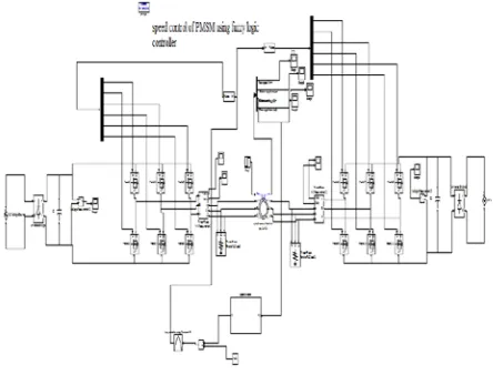
III.SIMULINK DIAGRAM
Figure 3.1 shows the simulation diagram for Performance analysis of dual inverter for PMSM using Fuzzy logic controller. In this diagram consist of two combination of inverters are connected with Permanent Magnet Synchronous motor. The fuzzy logic controller is used for proposed technique and it is used to control the speed and torque of PMSM.
Fig.2.Simulation diagram
The parameters of the BLDC motor drive like speed, voltage, current, torque and angle of response is measured through scope. Then the speed of the motor drive is taken as input for the Fuzzy control. After that the
output from two blocks is given to the input for fuzzy controller.
A fuzzy controller is change the frequency through pulse width modulation technique due to this the speed of the motor drive is controlled. The output of this controller is PWM signal which is given to the converter MOSFET’s through voltage controller. A Selective Harmonic PWM signal is given to the inverter to control the speed and torque repulsion by changing the frequency of PWM signal.
IV. FUZZY LOGIC CONTROLLER
A fuzzy control system is a control system based on 31Tfuzzy logic31T a 31Tmathematical31T
system that analyzes 31Tanalog31T input values in
terms of 31Tlogical31T variables that take on
continuous values between 0 and 1, in contrast to classical or 31Tdigital31T logic, which operates on
discrete values of either 1 or 0 (true or false respectively). Fuzzy logic has the advantage that the solution to the problem can be cast in terms that human operators can understand, so that their experience can be used in the design of the controller. This makes it easier to mechanize tasks that are already successfully performed by humans.
Fig.3.Block Diagram for Fuzzy Logic controller
Regarding a fuzzy system as either an approximate reasoned or functional approximate, it can be utilized in various ways in control systems. Instead of directly issuing the control signals, the function of fuzzy system lies in monitoring a low level direct
controller by outputting appropriate parameters to be used by the direct controller. The decision taken by the supervisor can be based on the current control performance or the operating conditions depending on the control strategies employed in the system. By treating fuzzy system as a representative model of the controller plant, third usage of the fuzzy system can be found, which is to place it into the various model based control structures found in traditional model.
V. SIMULATION RESULTS
Figure 4 shows the speed response for proposed system. The steady state is achieved at 0.1sec with less oscillation. For controlling the speed the system efficiency is improved. When compared to the existing system the speed oscillation is reduced so that the BLDC motor stability is not affected.
Figure.4. Speed Response of Proposed Method
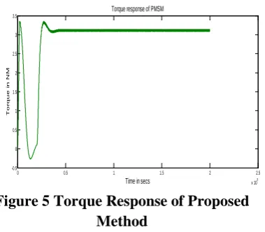
Figure 5 shows the Torque ripple of proposed system. From this system torque is improved up to 3kg. When compared to the existing system the system oscillation is improving so the system efficiency is also increased.
Figure 5 Torque Response of Proposed Method
Fig 6 shows the result Angle response for Permanent magnet Synchronous motor drive system.
Figure 6 Angle Response of proposed Method
Figure 7 shows the power factor correction proposed system. From this system oscillation is improved up to 0.1%. When compared to the existing system the system oscillation is improving so the system efficiency is also increased.
Figure 7 Current Response of Proposed Method
0 0.5 1 1.5 2 2.5
x 105 0 200 400 600 800 1000 1200 Time(ms) S peed( r pm ) Speed Response
0 0.5 1 1.5 2 2.5
x 105 -0.5 0 0.5 1 1.5 2 2.5 3 3.5
Time in secs
T
or
que i
n N
M
Torque response of PMSM
0 0.5 1 1.5 2 2.5
x 105 0 20 40 60 80 100 120
Time in secs
r ot or an gl e i n r ad ian s
Angle response for PMSM
0 0.5 1 1.5 2 2.5
x 105 -4 -3 -2 -1 0 1 2 3 4 5
Time in secs
C ur r e nt i n a m ps
Stator current response for PMSM
VI. CONCLUSION
Speed control of permanent magnet synchronous motor with fuzzy logic controller is presented in this work. This project mainly focuses on the study of Dual inverter and Fuzzy logic control method. The circuit has been designed on the Dual inverter and simulated using MATLAB. The simulation results were almost similar to the calculated values both the output voltage and voltage stress. An effective control technique is presented for the speed control of PMSM drive. The Fuzzy logic controller is used to regulate the speed of PMSM and also to reduce the torque ripples. The simulation results of both conventional and proposed technique was carried out for PMSM drive among them, proposed technique is more robust when load disturbances occurred. The simulation result shows the lower torque ripple, good speed regulator and high efficiency with proposed FLC than the conventional technique.
REFERENCE
[1] J.-K. Seok and S.-K.Sul, “Optimal flux selection of an induction machine for maximum torque operation in flux-weakening region,” IEEE
Trans. Power Electron., vol. 14, no. 4, pp.
700–708, Jul. 1999.
[2] M. Tursini, E. Chiricozzi, and R. Petrella, “Feedforward flux-weakening control of aurface-mounted permanent-magnet synchronous motors accounting for resistive voltage drop,” IEEE Trans.
Ind. Electron., vol. 57, no. 1, pp. 440–448, Jan.
2010.
[3] T.-S. Kwon and S.-K. Sul, “Novel antiwindup of a current regulator of a surface-mounted permanent-magnet motor for flux-weakening control,” IEEE Trans. Ind. Appl., vol. 42, no. 5, pp. 1293–1300, Sep./Oct. 2006.
[4] J.-M. Kim and S.-K. Sul, “Speed control of interior permanent magnet synchronous motor drive for the flux weakening operation,” IEEE
Trans. Ind. Appl., vol. 33, no. 1, pp. 43–48,
Jan./Feb. 1997.
[5] C.-H. Kim, M.-Y.Kim, H.-S. Park, and G.-W. Moon, “A modularized twostage charge equalizer with cell selection switches for series-connected lithium-ion battery string in an HEV,” IEEE Trans. Power Electron., vol. 27, no. 8, pp. 3764–3774, Aug. 2012.
[6] S. Kim and J.-K. Seok, “Maximum voltage utilization of IPMSMs using modulating voltage scalability for automotive applications,” IEEE Trans. Power Electron., vol. 28, no. 12, pp. 5639–5646, Dec. 2013.
[7] Y. Wang, D. Panda, T. A. Lipo, and D. Pan, “Open-winding power conversion systems fed by half-controlled converters,”
IEEE Trans. Power Electron., vol. 28, no. 5,
pp. 2427–2436, May 2013.
[8] H. Bai and C. Mi, “Eliminate reactive power and increase system efficiency of isolated bidirectional dual-active-bridge DC– DC converters using novel dual-phase-shift control,” IEEE Trans. Power Electron., vol. 23, no. 6, pp. 2905–2914, Nov. 2008.
VII.BIOGRAPHIES
Prakash. R was born in Tamilnadu
India, on May 19, 1986. He received his Master Degree in the application of Power electronics and drives from Anna university Chennai. His area of interest includes Power Electronics, Circuit Theory, Single phase Matrix Converter fed Induction Motor Drives. Currently he is working as a Assistant Professor in the department of Electrical and Electronics engineering at Vivekanadha Institute of Engineering and Technology for Women, Tamil Nadu, India.
Janani.S was born in Tamilnadu India, on May 27, 1993. She received her B.E degree in Electrical and Electronics Engineering from Anna University, Chennai. Currently she is pursuing M.E in Power Electronics and Drives at Vivekanadha Institute of Engineering and Technology for Women, affiliated to Anna University. Her area of Interest includes Power Electronics, DSP applications to Power Electronics and Solid State Drives, Converters, Speed control
of PMSM motor drive.