The BmnRoot framework for experimental data
processing in the BM@N experiment at NICA
Pavel Batyuk1, Konstantin Gertsenberger1,*,#, Sergey Merts1, and Oleg Rogachevsky1 1Veksler and Baldin Laboratory of High Energy Physics, JINR, 141980 Dubna, RussiaAbstract. A new generation of experiments for the relativistic nuclear physics is expected to be started up in the nearest years at the Nuclotron-based Ion Collider fAcility (NICA) under construction at the Joint Institute for Nuclear Research in Dubna. The main part of the facility is the essentially modernized accelerator Nuclotron. BM@N (Baryonic Matter at Nuclotron) is considered as a first stage towards realization of physics program available at NICA. It is a fixed target experiment aimed to work with the Nuclotron extracted beams of different species. The experiment had a set of technical runs since 2015. For a successful realization of the BM@N physics program, a well developed and tested software for simulation, digitization, reconstruction and analysis of collision events and other additional tasks is of utmost importance. The BmnRoot software developed in order to operate the mentioned tasks is described in this article. It includes modules for data digitizing obtained from BM@N detector systems, realistic simulation of signals in detectors, alignment of detectors, reconstruction of multiparticle interaction events, as well as all necessary systems for maintaining the databases of the experiment, visualization and providing information support for the experiment.
1 The BM@N experiment at NICA
Heavy-ion collisions at high energies provide a unique opportunity to study nuclear matter under extreme density and temperature. These conditions are well suited to investigate the compressibility of nuclear matter, in particular, the stiffness of the nuclear equation-of-state (EoS). Theoretical models, however, suggest different possible scenarios for these modifications, – so that new experimental data with high resolution and statistics are needed in order to disentangle the different theoretical predictions.
According to the JINR research program, the Nuclotron-based ion collider facility is being constructed as an ion accelerator complex for the range of collision energy from 4 to 11 GeV (for Au79+). BM@N [1] is the first experiment at the NICA accelerator complex to
study collisions of particles and ions with a fixed target at the energies up to 6 AGeV for different beam species (up to krypton, at the moment). It covers studies of elementary reactions (pp, pA) and cold nuclear matter, the properties of dense baryonic matter formed
*email: [email protected]
in course of heavy-ion collisions, in-medium effects, hypermatter and strangeness production, as well as hadron femtoscopy.
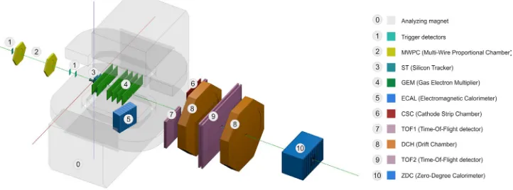
Since the proposed physics program to be performed with the experiment is wide, it requires a high precision level when extracting characteristics of particles produced in heavy-ion collisions. Due to this requirement, BM@N is constructed as a set of different sub-detector systems to combine high precision track measurements with time-of-flight information for particle identification. A target is located inside the large-acceptance dipole magnet with a magnetic field up to 1.2 T. Among the sub-detectors included in the experimental setup, the most important are inner tracker system, consisting of silicon and GEM detectors, and outer tracker, presented by Drift Chambers (DCH), Time-of-Flight detectors (TOF) and Cathode Strip Chamber (CSC) to measure “hard” and “soft” particles. A schematic view of the setup used in the last run is shown in Fig. 1.
Fig. 1. Schematic view of BM@N in the last run (March-April, 2018).
Since February 2015, a set of technical runs of the BM@N experiment has been performed with deuteron, carbon, argon and krypton beams with different targets (carbon, copper, etc.) at the beam kinetic energies of 2.3 – 5.14 AGeV. BM@N recorded a large amount of experimental data to be reconstructed and subsequently analyzed. Since the recently performed runs have been considered as technical ones, issues concerning detector performance at different energy and beam regimes played an important role and was studied extensively.
2 The BmnRoot framework
Obviously
,
the development of suitable software is a key feature in the success of the experiments. The software should allow one, at least, to perform a simulation of particles passing through detectors and to do a reconstruction of events taking into account specific features of detectors where the reconstruction is being done.The BmnRoot framework [2, 3] provides a powerful tool for detector performance studies, event simulation, and development of algorithms to be used for reconstruction and physics analysis of events recorded by the BM@N facility. The software is based on the FairRoot [4] framework originally used for the CBM experiment. The FairRoot package includes common core services to cover and simplify detector simulation, reconstruction and data analysis.
in course of heavy-ion collisions, in-medium effects, hypermatter and strangeness production, as well as hadron femtoscopy.
Since the proposed physics program to be performed with the experiment is wide, it requires a high precision level when extracting characteristics of particles produced in heavy-ion collisions. Due to this requirement, BM@N is constructed as a set of different sub-detector systems to combine high precision track measurements with time-of-flight information for particle identification. A target is located inside the large-acceptance dipole magnet with a magnetic field up to 1.2 T. Among the sub-detectors included in the experimental setup, the most important are inner tracker system, consisting of silicon and GEM detectors, and outer tracker, presented by Drift Chambers (DCH), Time-of-Flight detectors (TOF) and Cathode Strip Chamber (CSC) to measure “hard” and “soft” particles. A schematic view of the setup used in the last run is shown in Fig. 1.
Fig. 1. Schematic view of BM@N in the last run (March-April, 2018).
Since February 2015, a set of technical runs of the BM@N experiment has been performed with deuteron, carbon, argon and krypton beams with different targets (carbon, copper, etc.) at the beam kinetic energies of 2.3 – 5.14 AGeV. BM@N recorded a large amount of experimental data to be reconstructed and subsequently analyzed. Since the recently performed runs have been considered as technical ones, issues concerning detector performance at different energy and beam regimes played an important role and was studied extensively.
2 The BmnRoot framework
Obviously
,
the development of suitable software is a key feature in the success of the experiments. The software should allow one, at least, to perform a simulation of particles passing through detectors and to do a reconstruction of events taking into account specific features of detectors where the reconstruction is being done.The BmnRoot framework [2, 3] provides a powerful tool for detector performance studies, event simulation, and development of algorithms to be used for reconstruction and physics analysis of events recorded by the BM@N facility. The software is based on the FairRoot [4] framework originally used for the CBM experiment. The FairRoot package includes common core services to cover and simplify detector simulation, reconstruction and data analysis.
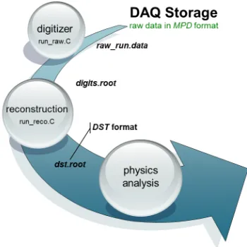
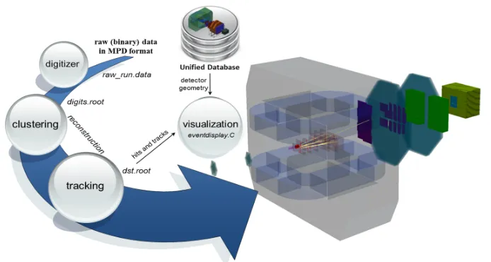
Fig. 2 shows an overview of experimental data processing available with the BmnRoot software. It is seen that the data processing has a multi-level structure. Firstly, raw data from the detectors recorded by the Data Acquisition System (DAQ) are converted into the
ROOT [5] format and digitized (see section 3). Secondly, a procedure aimed to reconstruct parameters of particles in the detectors is applied. Thirdly, as a final step of the data chain, the physics analysis is performed to investigate the physical properties of the nuclear matter produced in course of collisions.
Fig. 2. Experimental data processing chain in the BmnRoot framework.
3 Experimental data decoding procedure
An event decoding procedure has been completed and fully integrated into the BmnRoot framework. It has been tested during recent available runs of the BM@N experiment.
The decoding consists of two base procedures, converter and decoder, as a whole. The converter is used to get recorded raw data and extract information on DAQ-digits (ADC, TDC, HRB, TQDC, etc.) in accordance with the given Data Acquisition format. When the converter execution has finished, the obtained output is written to a ROOT tree. The decoder serves for tasks that are more complicated. It reads DAQ-digits from the ROOT tree, recorded at the previous step, to process them taking into account mapping (a link between channels of electronics and detector elements) for a detector to be decoded. The final output of the data decoding procedure is a file containing digits for all detectors participated in the procedure. The digits presented there are considered as “physical” ones (contrary to those obtained at the first stage of the data decoding procedure when executing the converter) and could be used, if necessary, for the reconstruction procedure aiming to produce input for any kind of physics analysis. To get more information on the data decoding procedure, one is addressed to [6].
4 Alignment of inner tracker of the BM@N experiment
do the alignment of the inner tracker of the experimental setup, thus it was tested with input acquired from the inner tracker. In the future, it should be extended to the outer tracker system of the BM@N experiment: the drift chambers (DCH) and the cathode strip chambers (CSC).
Because a typical alignment problem looks like a multivariate minimization problem, the ALCOPACK software can be used in two modes. The first one allows to start the alignment procedure aiming at obtaining rough corrections to the elements of the detectors participating in the procedure. After that, if necessary, the obtained corrections could be used as a first approximation to be passed to ALCOPACK when running the software in the second mode. The presence of two working modes gives a possibility to find a minimum that satisfies previously defined conditions of minimization.
In addition to these features, the ALCOPACK software can work effectively with a mechanism of Lagrange multipliers available within Millepede-II. It looks as a very important point, since the mechanism is used to prevent a possible undesirable total shift of a detector that could occur when finding minimum.
The developed software was tested with existing experimental data. The last test has been done using recorded experimental dataset representing interactions of an argon beam with a lead target at available kinetic energy of the beam close to 3.2 AGeV. The data used for the alignment procedure are recorded in absence of magnetic field thus being straight tracks, obviously, obtained after the tracking procedure, in the inner tracker.
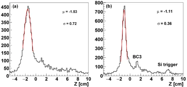
Fig. 3. Distribution of z-coordinates of reconstructed vertices before (a) and after (b) alignment.
The distributions of z-coordinates of the reconstructed vertices before (a) and after (b) alignment are presented in Fig. 3. First, the procedure increases sufficiently the number of tracks to be considered as tracks going from the primary vertex. Secondly, the value found for z-position of the primary vertex becomes closer to the value that corresponds to the position of the primary vertex according to the geometrical precise measurements performed in the beginning of the experiment. Moreover, the procedure allows one to reduce the width of the primary vertex by a factor of two. Thirdly, the distribution of z-coordinates of the primary vertex shows more clearly a set of “artificial” (in physical sense) secondary vertices produced by trigger counters.
5 Event reconstruction in BM@N (tracking)
do the alignment of the inner tracker of the experimental setup, thus it was tested with input acquired from the inner tracker. In the future, it should be extended to the outer tracker system of the BM@N experiment: the drift chambers (DCH) and the cathode strip chambers (CSC).
Because a typical alignment problem looks like a multivariate minimization problem, the ALCOPACK software can be used in two modes. The first one allows to start the alignment procedure aiming at obtaining rough corrections to the elements of the detectors participating in the procedure. After that, if necessary, the obtained corrections could be used as a first approximation to be passed to ALCOPACK when running the software in the second mode. The presence of two working modes gives a possibility to find a minimum that satisfies previously defined conditions of minimization.
In addition to these features, the ALCOPACK software can work effectively with a mechanism of Lagrange multipliers available within Millepede-II. It looks as a very important point, since the mechanism is used to prevent a possible undesirable total shift of a detector that could occur when finding minimum.
The developed software was tested with existing experimental data. The last test has been done using recorded experimental dataset representing interactions of an argon beam with a lead target at available kinetic energy of the beam close to 3.2 AGeV. The data used for the alignment procedure are recorded in absence of magnetic field thus being straight tracks, obviously, obtained after the tracking procedure, in the inner tracker.
Fig. 3. Distribution of z-coordinates of reconstructed vertices before (a) and after (b) alignment.
The distributions of z-coordinates of the reconstructed vertices before (a) and after (b) alignment are presented in Fig. 3. First, the procedure increases sufficiently the number of tracks to be considered as tracks going from the primary vertex. Secondly, the value found for z-position of the primary vertex becomes closer to the value that corresponds to the position of the primary vertex according to the geometrical precise measurements performed in the beginning of the experiment. Moreover, the procedure allows one to reduce the width of the primary vertex by a factor of two. Thirdly, the distribution of z-coordinates of the primary vertex shows more clearly a set of “artificial” (in physical sense) secondary vertices produced by trigger counters.
5 Event reconstruction in BM@N (tracking)
A proposed algorithm to reconstruct parameters of charged particle tracks is based on cellular automaton [8]. The algorithm is applied to the inner tracker system of BM@N and planned to be extended to the outer tracker also. The algorithm is built on cells. It is defined
and considered as a line segment connecting two hits pertaining to different planes of the inner tracker.
In general, the main steps of the algorithm are:
- Creation of cells. At this stage, all possible connections between neighbouring
detector planes are created. A restriction on the maximal value of the slope in ZX and ZY planes is used when creating cells.
- Calculation of cell states. This stage is done iteratively. At the first step, all cells have a state equal to unity. Further, in course of iterations, if two cells have a common hit and similar slopes in ZX and ZY planes, then the state of the next cell is increased by unity. The iterations are done over all elements (planes) of the inner tracker. It leads to calculation of final states for all cells.
- Creation of candidates to be considered as future tracks. At this stage, the cells
found are unified with their left neighbours if their state difference is equal to unity. As a result, an array of candidates to be tracks consisting of a few cells is created. A candidate is rejected if having less than four hits. “Kept”' candidates are passed through procedures aimed to estimate vector of state and covariance matrix by a fit with circle.
When all the candidates are found, the next steps of the algorithm are related to improvement of their parameters by the Kalman filter in order to do a correct sorting of the candidates aiming to write the best ones to an output array for further physics analysis.
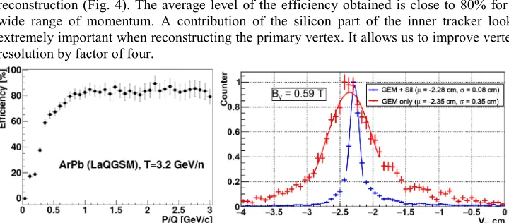
A set of quality assurance tests done with the help of Monte Carlo input representing interactions of an argon beam with kinetic energy of order of 3.2 AGeV with a lead target showed reasonable values of tracking efficiency and good precision of primary vertex reconstruction (Fig. 4). The average level of the efficiency obtained is close to 80% for a wide range of momentum. A contribution of the silicon part of the inner tracker looks extremely important when reconstructing the primary vertex. It allows us to improve vertex resolution by factor of four.
Fig. 4. Tracking efficiency and vertex resolution obtained in quality assurance tests.
6 Central database of the BM@N experiment for offline event
processing
presenting state of detector sub-systems and data used to control operation of offline algorithms.
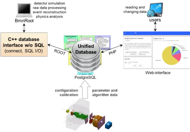
The database provides a unified access for all collaboration members granting different permissions, correct multi-user data processing, ensuring the information being access is up to date, data consistency and integrity, excluding multiple duplication and use of outdated data. The automatic backup of the database will ensure that stored data of the experiment will not be lost due to software or hardware failures.
To integrate the database with the BmnRoot software aiming at providing access to required data for algorithms to be processed, an interface with a set of basic and auxiliary functions has been implemented. It is a C++ database interface that is used to get information for detector simulation, raw data processing, event reconstruction and physics analysis. One of the main benefits of the interface is a possibility to work with the content of the database without SQL statements.
The schematic diagram of the relationships for the database is shown in Fig. 5. At present, the database is filled with the information on performed runs of the BM@N experiment, and is used intensively when executing algorithms of raw data processing, reconstruction, and physics analysis. The Web-interface of the database is being developed. It serves to simplify reading and changing data of the experiment over the Web. Future versions of the database could be used for the future MPD experiment as a continuation of the NICA physics program or even for other high-energy physics experiments.
Fig. 5. General scheme of database relationships for the BM@N experiment.
7 Event Display for visualization of experimental event data
presenting state of detector sub-systems and data used to control operation of offline algorithms.
The database provides a unified access for all collaboration members granting different permissions, correct multi-user data processing, ensuring the information being access is up to date, data consistency and integrity, excluding multiple duplication and use of outdated data. The automatic backup of the database will ensure that stored data of the experiment will not be lost due to software or hardware failures.
To integrate the database with the BmnRoot software aiming at providing access to required data for algorithms to be processed, an interface with a set of basic and auxiliary functions has been implemented. It is a C++ database interface that is used to get information for detector simulation, raw data processing, event reconstruction and physics analysis. One of the main benefits of the interface is a possibility to work with the content of the database without SQL statements.
The schematic diagram of the relationships for the database is shown in Fig. 5. At present, the database is filled with the information on performed runs of the BM@N experiment, and is used intensively when executing algorithms of raw data processing, reconstruction, and physics analysis. The Web-interface of the database is being developed. It serves to simplify reading and changing data of the experiment over the Web. Future versions of the database could be used for the future MPD experiment as a continuation of the NICA physics program or even for other high-energy physics experiments.
Fig. 5. General scheme of database relationships for the BM@N experiment.
7 Event Display for visualization of experimental event data
A graphical representation of events occurring in the detector (event display) is of utmost importance in modern high-energy physics experiments. Such visualization systems are used at the design stage for model and reconstruction algorithm checking and debugging, analysis of algorithms for event data processing by experts, data reconstruction and physics analysis visualization for a better understanding of the detectors and collision event structure by users, and for demonstration and presentation of works of the experiment. An
event display is also required for online visual presentation of selective events during the experiment run as a monitoring system, for visual control and debugging of current events at the run stage. To develop such a system, it is recommended to use specialized software tools based on graphic packages that use hardware capabilities of modern video cards to update quickly a graphical representation of physics data when necessary.
The high-level graphics package EVE (Event Visualization Environment) [9] being a part of the ROOT environment looks like a good fit to be used for displaying detector geometries and events of the BM@N experiment. The EVE package originally developed by the ALICE collaboration uses the ROOT GUI and the OpenGL library to display three-dimensional objects and their two-three-dimensional projections. The EVE classes were developed primarily for creation and management of objects in high-energy physics experiments, such as raw data, hits, clusters, points and tracks.
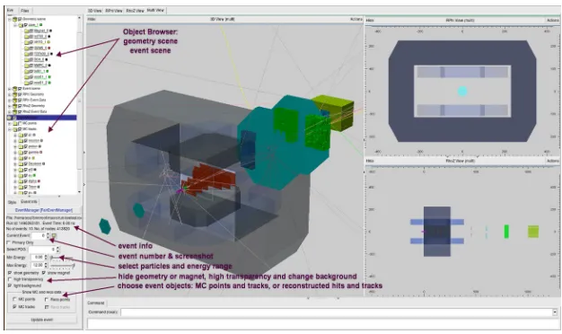
The developed event display allows users to do a graphical representation of data (experimental and simulated), such as tracks and their points (hits), triggered calorimeter towers, and the BM@N detector geometries in different projections and views. It offers full interactivity including zooming, rotation and working with each object, and is integrated into the BmnRoot software to combine different stages of the event data processing with a graphical representation of these events to evaluate and check correctness of developed algorithms.
Fig. 6 shows a visualization of the BM@N geometry in the mode of simultaneous viewing of three-dimensional view and projections. An important element of the visualization system is a display filter that allows customizing the parameters of data being presented on the screen. Users can select a convenient graphical representation, events to be displayed, particles with definite PDG codes or in a given energy range, objects to be presented on the screen, configure object parameters, set light sources, desired colors and many other visualization settings. Tracks of different particles are highlighted by different colors to be clearer.
Fig. 6. Views and projections of the BM@N setup in developed event display.
Fig. 7. Visualization of tracks in a carbon-carbon event.
8 Conclusions
The BmnRoot framework provides all the tools needed for the processing of the experimental data obtained from the BM@N experiment. The methods of raw data converting, detector alignment and event reconstruction were implemented. The user can describe geometry of the detector in detail and visualize the geometry and detector responses for considered events by the event display. Many software systems such as, for example, the BM@N Unified Database, the Event Display and Software Test System have been developed, but many packages should be added or improved for the experimental data taking and data processing in distributed systems. The detailed information on the BmnRoot framework is presented on the technical Web site for the NICA experiments:
mpd.jinr.ru.
References
1. BM@N Collaboration, BM@N Project. Studies of Baryonic Matter at the Nuclotron
(http://bmnshift.jinr.ru/wiki/lib/exe/fetch.php?media=bmnproject_2016.pdf, 2016) 2. BM@N project, “BmnRoot” [software], version apr17, 2018. Available from
https://git.jinr.ru/nica/bmnroot/tree/dev [accessed 2018-10-28]
3. K. Gertsenberger, S. Merts, O. Rogachevsky, A. Zinchenko, Eur. Phys. J. A., 52, 8 (2016)
4. FAIR project, “FairRoot” [software], version 17.10c, 2018. Available from https://github.com/FairRootGroup/FairRoot/tree/v-17.10c [accessed 2018-10-28] 5. ROOT project, “ROOT” [software], version 6.14.0, 2018. Available from
https://github.com/root-project/root/releases/tag/v6-14-00 [accessed 2018-10-28] 6. I. Gabdrakhmanov, M. Kapishin, S. Merts, CEUR-WS, 2023 (2017)
7. V. Blobel, C. Kleinwort, hep-ex/0208021 (2002)