Transactions, SMiRT-23
Manchester, United Kingdom - August 10-14, 2015 Division VI, Paper ID 235
Fuel Element High-Temperature Bowing Behaviour under External
and Internal Heating: Comparative Study
Alexander Belov1, Brian Leitch2, and Anthony Williams3
1Research Scientist, Canadian Nuclear Laboratories, Canada
2Senior Mechanical R&D Engineer, Canadian Nuclear Laboratories, Canada
3Research Scientist, Canadian Nuclear Laboratories, Canada
ABSTRACT
Internal and external heating are two methods commonly used in fuel element and bundle high-temperature deformation behaviour experiments. External heating is preferred in some cases because of its simplicity. However, the radial temperature gradient produced by this method in an element is in the opposite direction to that generated under in-reactor prototypical conditions where the maximum temperature occurs at the fuel centre. The impact of such a discrepancy upon the element deformation response is unknown.
A study was undertaken to address this knowledge gap through a direct comparison of the element bowing behaviour under external and internal heating conditions. The experiments conducted on horizontal simply supported CANDU type non-uranium fuel element simulators showed a significant difference in the element sag rates during exposure to a steady temperature of 800°C as well as in the residual plastic bow measured after the tests. No appreciable
difference in the response was found in the range below 700°C.
To support these experiments, a finite element model of a CANDU fuel pin was created using the ANSYS finite element software. The model is fully three dimensional and includes the fuel pellets and sheathing as separate components, which interact via contact elements.
INTRODUCTION
Internal and external heating methods are commonly used in experiments related to the nuclear fuel element and fuel bundle high-temperature deformation behaviour under reactor nominal, upset and accident conditions. The external heating is preferred in some cases because implementation of this method is relatively simple and allows experiments to be performed on intact, as manufactured, elements and bundles, for example the CANDU fuel bundle high-temperature test utilising superheated steam flow discussed in the paper by Kohn et al. (1985). The major challenge associated with use of the external heating is that the resulting temperature profiles across the tested elements are not representative of those generated in real fuel elements under prototypical in-reactor conditions. In the latter case, the peak temperatures occur at the fuel centre line, whereas in the instance of external heating the radial temperature profiles have a maximum at the element sheath outer surface and a minimum at the fuel pellet centre. The impact of such an inverse temperature distribution upon the fuel element deformation response has not been investigated yet.
EXPERIMENTAL
Internally Heated Element Experiment
The experiment was performed on a horizontal simply supported FES. The FES was constructed of Zircaloy-4 fuel sheath, cylindrical pellets made of AD 995 type alumina ceramic simulating UO2 nuclear fuel, and a heating element. The nominal dimensions of the sheath (outer diameter 15.2 mm, wall thickness 0.38 mm, and 489.5 mm in length) and pellets (outer diameter 14.32 mm and length 22.85 mm) were the same as in CANDU Pickering type nuclear fuel elements. The evaluated average sheath-to-pellet diametrical gap is 0.06 mm. Internal indirect heating of the FES was produced by way of passing an alternating electrical current through a tungsten – 25% Re wire heating element located in the pellet’s central hole.
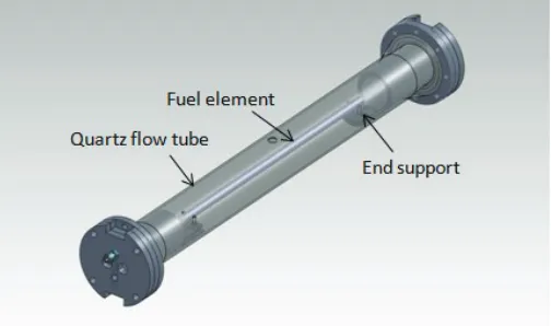
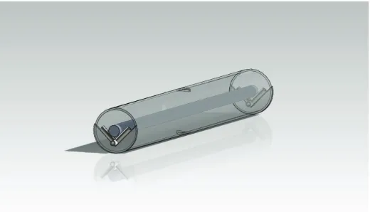
During the tests, the fuel element specimen, instrumented with thermocouples, was placed onto cantilever end supports located inside a horizontal quartz flow tube as shown in Figure 1. The supports provided only a vertical restraint allowing the FES to expand axially and rotate. The span between the unrestrained end supports in these tests was 460 mm. The test was carried out in a steady flowing argon gas inert atmosphere.
Figure 1. External heating test setup.
The FES bowing deformation was measured at the specimen mid-length using a high-accuracy Keyence series LK-G laser displacement sensor. Type K thermocouples in 0.5 mm diameter stainless steel sheaths were spot welded to the fuel sheath outer surface. A total of 10 thermocouples were installed at the 20 mm, 1/4 - length, 1/2 - length, and 3/4 - length axial positions.
Externally Heated Element Experiment
In the External heating experiments, the high density radiant energy emitted from linear infrared (IR) sources was optically focused onto a target, a FES, placed in the centre of the clamshell test chamber. Twelve short-wave tubular halogen lamps arranged in a circular array were utilized as linear multiple infrared radiant energy sources surrounding the target. The lamps were coupled with water cooled parabolic diffuse reflectors that enhance and direct IR energy to the target.
The element simulator used in this experiment was similar to that employed in the Internal heating experiment, that is comprised of the Pickering type Zircaloy sheath and alumina ceramic pellets with a central hole. No heating wire was placed in the hole. The estimated fuel-to-sheath gap for this element assembly is 0.02 mm.
Table 1: Experiment Condition Summary.
Cycle No. Dwell
temperature set point
[°C]
Internal Heating External Heating
Heating rate* [°C/s]
High-temperature dwell period
[min]
Heating rate* [°C/s]
High-temperature dwell period
[min]
1 600
0.91 15.5 0.4 8
2 600 0.6 8.2 0.4 11
3 600 0.73 9.6 0.4 11
4 800
0.57 7.5 0.3 5.5
5 800 0.59 6.3 0.3 5.4
* average over the temperature ramp-up period
The sheath temperatures were measured using five thermocouples installed at the 25 mm and the midlength axial positions. A model ODS 505 DSE (Danish Sensor Engineering)
high-temperature-target laser displacement sensor monitored element bowing deflections in the midplane.
The FES was exposed to five sequential temperature cycles. The cycle parameters, listed in Table 1, were similar to those of the Internal heating experiment. The fuel sheath temperature was automatically controlled using the temperature programmer provided in the IR heater power supply system.
COMPUTER MODELLING
A major motivation for these experiments has been to support the development of computational fuel models, intended to simulate the 3-dimensional deformation of fuel pins under off normal and accident conditions. A 3D model of the experiment was generated using the ANSYS finite element code suite (2013), with the intent of simulating the sagging behaviour of the fuel pin observed in these tests.
At present, only the internally heated fuel element simulator test has been simulated, as the heat flux at the fuel sheath surface is indeterminate for the externally heated experiments.
Components, Elements and Mesh
The mechanical deformation of a fuel pin is significantly influenced by the presence of the pellets inside the sheath. As the ceramic pellets have a higher coefficient of thermal expansion than the Zircaloy fuel sheath, the interaction of the fuel pellets with the fuel sheath changes with
temperature and any fuel model intended to predict fuel pin deformation must be able to account for this interaction. The most direct way to do this is to model the pellets and sheath as 3D solids and model the mechanistic interaction between these components. Hence a 3D finite element model was constructed that included the fuel pellets and the fuel sheath as separate components that interact via contact elements.
The model used to simulate the tests is that of a prototypical fuel pin rather than the fuel element simulator used in the experiment. That is to say the heating wire is not modelled directly and the model of the pellets does not include a central hole, however the thermal behaviour of the wire is simulated by application of a time dependant volumetric heat generation within a repetitive central portion of the fuel pellet. As the sagging of the fuel pin is gravity driven, the density of the fuel pellets was changed from UO2to Al2O3, and was further corrected to account for the
presence of the central hole, i.e., the density of the pellets in the model as adjusted to ensure that the weight of the pellets matched those used in the experiment.
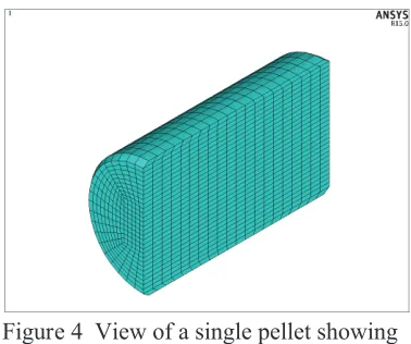
Figure 3 shows this basic geometry. To reduce computation time the fuel pin is assumed to have two planes of symmetry necessitating the simulation of only one quarter of the pin. The model includes ten half pellets and one quarter pellet at the mid plane and is equivalent to a full fuel pin containing 21 ceramic pellets. The pellets include chamfers and a detailed view of a pellet showing these chamfers and the finite element mesh is shown in Figure 4.
unduly affect the accuracy of the simulation as the axial gap between the pellets and the end-caps prevents the pellets from interacting with the end-caps even at high temperature.
Figure 3 Basic geometry of the fuel pin model
Figure 4 View of a single pellet showing chamfers and the finite element mesh
The fuel pellets were evenly distributed with an initial pellet-to-pellet gap of 0.06 mm. It can be noted that several simulations were conducted with varying pellet-to-pellet spacing, including zero gap, but the results were insensitive to this parameter.
The finite element mesh used in the fuel pellets and fuel sheath are also shown in Figure 3 and Figure 4. The solid elements used are 20 node hexahedral elements of ANSYS type SOLID186.
Pellet-to-pellet contact and pellet-to-sheath contact is modelled using contact elements. These are 2D elements which are attached to the surfaces of the components. For each possible contacting pair of surfaces, one surface is designed as the contact surface and the other as the target surface. In this model, the contact elements are of ANSYS type CONTA174 and the target elements are of type TARGE170.
Mechanical and thermal loads, including frictional forces, are transferred between components via these contact elements. The pellet-to-sheath heat transfer coefficient is a function of the pellet-to-sheath interface pressure or gap size. ANSYS includes several options for contact modelling the most common being the penalty method, which is the option chosen for this model. A description of this model is provided in the ANSYS manual (2013).
ANSYS allows the use of a damping factor to prevent rigid body motion when objects break contact and become potentially unconstrained. This damping factor is termed the “contact opening stiffness”, and is important in obtaining a converged solution when the temperature of the fuel pellets falls and the fuel-to-sheath gap opens. Simulations were run with and without this damping factor to determine its influence on the results.
Material Properties
The following material properties are used in the model.
For the Al2O3Pellets
For the Zircaloy Sheathing
Density at 300 K = 6440 kg/m3, Coefficient of thermal expansion = 6.72 × 10⁻⁶
The sheath material properties include a bilinear model to account for Zircaloy-4 plasticity using a variation of the yield stress model in the MATPRO handbook (2003). The sheath behaviour also includes a creep model which uses the diffusional creep term from the AECL’s ELOCA code Zircaloy creep model. The creep rate is given by:
where:
ė
= strain rate (s-1)F = creep rate coefficient = 6.34×10⁶/G2(G is the bulk modulus; see below) σa= applied stress (MPa)
d = grain size (µm) (in the current model, d = 3 µm for the α-phase and 100 µm for the β-phase) m = exponent = 2.0 for the α-phase and 1.9 for the β-phase
Q = activation energy / the gas constant R (K-1) T = temperature (K)
G = the bulk modulus given by the empirical expression = 1000(36.3-0.0223(T-273))
Coefficient of Friction
The coefficient of friction between the fuel pellets and the sheath was expected to be a factor in determining the stiffness of the fuel pin and the rate of sagging of the fuel pin, but at present there is no direct measurement for this value available. A number of simulations were implemented with varying values for the coefficient of friction from 0.01 to 1. It was found that there was very little impact on the sagging rate for values between 0.01 and 0.2, but values higher than 0.2 noticeably increased the stiffness of the pin and reduced sagging. Very low values for the coefficient of friction affect the stability of the solution as the pellets become free to slide within the sheath resulting in rigid body motions that prevent convergence to a solution. It was found that an optimal value for the coefficient of friction between the fuel pellets and the sheath is 0.1.
Boundary Conditions and Constraints
The thermal boundary condition used in the model is the sheath temperature as supplied by the TC1 thermocouple, see Figure 5. The thermal load is applied to the centre axis of the fuel pellets to represent the heating wire.
Constraints of zero displacement in the z or x directions are imposed on nodes on the “cut” surfaces corresponding to planes of symmetry. One node 230 mm from the fuel pin center line is constrained to zero displacement in the y and x directions, but allowed to move freely in the z direction to simulate the supports on the fuel pin used in the experiment.
RESULTS
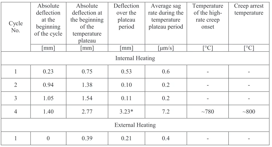
The key parameters characterizing the FES deformation behaviour observed in the both external and internal heating experiments are gathered in Table 2.
Bowing Behaviour under Internal Heating Conditions
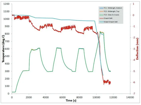
The captured response of the internally heated FES to the applied temperature cycles is shown in Figure 5.
Figure 5 FES sheath deflection and temperatures measured at the element midlength in the internal heating experiment
In the 1stcycle, high-temperature dwell set-point of 600°C, the magnitude of the fuel element bowing displacement increased at a variable rate during the temperature ramp-up. The net deflection produced over the ramp-up period, from 300°C to 600°C, is 0.75 mm. During the temperature plateau, the element sagged at a near-constant rate of ~0.6 μm/s. The total deflection gained over this period is ~0.53 mm. After the power shut off followed by the specimen cooling down to 300°C, the absolute deflection slightly decreased, however, the element did not return to the initial position. The residual displacement measured at the end of the 1stcycle is ~0.8 mm.
In the 2ndcycle, the element deformation response was somewhat different. The deflection monotonically increased over the temperature ramp period and continued into the hold period with a near-constant rate. The average bow rate reduced by a factor of three to an amount of 0.2 μm/s. The permanent lateral displacement developed over the 2ndcycle also declined to 0.3 mm.
The element deformation response in the 3rd600°C peak temperature cycle was very similar to that observed in the 2ndcycle. The measured values of the element bow and bow rate over the hold period were the same. The residual bow resulting from the cycle is ~0.2 mm.
The 4thcycle, conducted at peak temperature of ~800°C, resulted in significant plastic
Results of the Computer Modelling
An example of the thermal solution from the fuel pin model is shown in Figure 6 and the corresponding von Mises stress in the fuel sheath is shown in Figure 7.
Figure 6 Fuel temperature (K) calculated by the model at 1100 s
Figure 7 Von Mises stress (Pa) in the fuel sheath at 1100 s
The computer model was used to calculate the amount of fuel element sagging and the comparison against the experimental results for the internally heated fuel element simulator is shown in Figure 5. As can be seen from the plot of the Von Mises stress in the fuel sheath, Figure 7, the interaction between the pellets and the sheath is important and results in a stress concentration at the pellet-to-pellet interfaces. From Equation (1) it is clear that the creep rate and hence sagging rate is strongly influenced by local stress and for any such model to be accurate it must correctly account for the stress concentrations caused by the fuel pellets.
Figure 5 shows that the model under predicts the amount of fuel pin sagging for the first three 600°C cycles, but shows the correct general behaviour in that significant permanent deformation occurs in the first transient only. For the 4thtransient once the temperature exceeds 600°C, the sagging rate increases dramatically and the sagging rate calculated by the model is a good approximation of that observed in the experiment. This suggests the low temperature creep behaviour of the model could be further improved upon to better predict the slower sagging rates observed below 600°C.
Bowing Behaviour under External Heating Conditions
The plot of the recorded FES transient temperature and deformation behaviour under the applied radiant heat cycles is shown in Figure 8.
For the 1stcycle, the measured sheath bow, gained over the temperature hold, and the evaluated sag rate are 0.21 mm and 0.4 μm/s, respectively. These values are below those observed in the Internal heating experiment. The residual bow measured at the end of the cycle is 0.6 mm.
Figure 8 FES sheath deflection at the midpoint and temperatures measured in the External heating experiment
In the 3rdlast cycle with 600°C peak temperature, the FES deformation behaviour was pretty much the same as in the previous, 2nd, cycle. In particular, the bow gained over the temperature dwell period is 0.15 mm and the average sag rate is 0.24 μm/s.
The bowing response captured in the last 800°C set-point temperature cycle can be subdivided into three regions with near-steady sag rates increasing in increment: 0.21 μm/s for the region (I) with temperature ranging from 360-625°C; 1.1 μm/s for the region (II) corresponding to the temperature range 625-720°C; and 3 μm/s during the dwell period, region (III), where the peak temperature of about 720°C was
maintained. The average sag rate and permanent bow of 2.1 mm developed in this cycle are well below that observed in the same cycle under Internal heating conditions.
Table 2 FES bow response measured in the midplane
Cycle No.
Absolute deflection
at the beginning of the cycle
Absolute deflection at the beginning
of the temperature
plateau
Deflection over the
plateau period
Average sag rate during the
temperature plateau period
Temperature of the
high-rate creep onset
Creep arrest temperature
[mm] [mm] [mm] [μm/s] [°C] [°C]
Internal Heating
1 0.23 0.75 0.53 0.6 -
-2 0.94 1.38 0.10 0.2 -
-3 1.05 1.54 0.11 0.2 -
-4 1.40 2.77 3.23* 7.2 ~780 ~800
Cycle No. Absolute deflection at the beginning of the cycle
Absolute deflection at the beginning of the temperature plateau Deflection over the plateau period Average sag rate during the
temperature plateau period
Temperature of the
high-rate creep onset
Creep arrest temperature
[mm] [mm] [mm] [μm/s] [°C] [°C]
2 0.6 0.53 0.15 0.23 -
-3 0.7 0.74 0.15 0.24 -
-4 0.79 1.85 1.1 3.0 ~720 ~715
*sag deflection gained over the time period equal to the temperature plateau duration in the 4thcycle of the external heating experiment (5.5 min) is 2.73 mm.
CONCLUSIONS
The experiments revealed no significant difference in the bowing behaviour of the fuel elements subjected to the Internal, indirect resistance, and External, radiant, heating at temperatures below the onset of the high-rate creep observed in this study in the range of 720-780°C.
By contrast, there is a considerable difference in the FES deformation response at temperatures above the high-rate creep temperature threshold. In the experiment utilising the Internal indirect heating method, the sag rate during the high-temperature hold period and element permanent bow measured after exposure to the 800°C peak temperature cycle significantly exceeds that produced in the externally heated element.
A 3D finite element model of a fuel element was used to calculated fuel element sagging rates, and produced a good approximation to the observed sagging rate above 600°C, but under predicted the amount of fuel pin sagging below 600°C. This behaviour is likely due the temperature sensitivity of the Zircaloy creep correlation used in the fuel pin model. Further refinement of this model is required to better simulate the low sagging rates observed below 600°C.
ACKNOWLEDGEMENT
The authors acknowledge Canadian Nuclear Laboratories for funding this work. The contributions of Alan West who assembled and conducted the tests as well as Normand Lair who prepared the
instrumented sample are greatly acknowledged.
REFERENCES
Kohn, E., Hadaller, G.I., Sawala, R.M., Archinoff, G.H. and Wadsworth, S.L. (1985). “CANDU Fuel Deformation During Degraded Cooling (Experimental Results)”, Proc. Canadian Nuclear Society Conference, Ottawa, Canada.
ANSYS Inc., (2013), “ANSYS Mechanical Application User's Guide”, Release 15.0, distributed as online help with ANSYS Release 15.