Design of Controller Board and DC-DC
Interface for Remote Sensing Satellites
Basavaraj1, SK Najeer ahemmad 2, Dr.Veena Devi Shasthrimath3
M.Tech Student, Dept. of Electronics and Communication, NMAM Institute of Technology, Nitte, Udupi District,
Karnataka, India1
Sci/Eng,’SE’, DHSG ISAC,ISRO, Bengaluru, Karnataka, India 2
Professor, Dept. of Electronics and Communication, NMAM Institute of Technology, Nitte, Udupi District, Karnataka,
India3
ABSTRACT:Future sub meter resolution Cartographic Satellites carry advanced high resolution cameras capable of producing resolution of the images as small as 0.3m. The data rates from these satellites are as high as several Gbps. The transmission band within which the data has to be sent to the ground stations is limited. Hence the data needs to be compressed suitably with a certain loss compression algorithms which minimize the distortions. These satellites need to be designed with modular compression units to cater to high data rate requirements. For higher swath requirements there may be multiple units operating simultaneously, each unit has to be controlled by a controller unit which initializes the compression units before it starts processing the image data. The controller unit has the functionalities like providing the secondary voltage, providing the power reset, configuring and initializing the compression units, loading the NUC(Non Uniformity Correction) parameters, providing the commands and receiving the health of the compression units.
KEYWORDS: MIL-STD 1553B, POL, OVP, SPI, Controller, NUC, Relay, DC-DC.
I. INTRODUCTION
The Base band Data Handling System (BDH) of Remote sensing satellites acquires image data from high resolution payloads formats and transmits to ground through RF interface or stores in Solid Stare Recorder during non-visibility. The data rate from these payloads is very high to be transmitted to ground in limited band width channel. Hence the payload data is compressed in BDH system using efficient compression algorithm. The BDH system comprises of compression boards which can compress the data with less distortion at higher compression ratios. BDH system also incorporates the play back unit with performs channels coding, randomization and formatting of the payload data before transmitting to ground. The current paper discusses about the controller board which configures, commands, provides the secondary voltages and collects the health parameters of compression as well as playback boards. This controller board also acts as a slave to the 1553 bus control unit of the space craft. Controller board receives commands from the 1553 interface to perform the above said functions. The controller board is also used to receive the raw bus from space craft power systems and converts to secondary voltages required for digital logic using DCDC converters, POL and LDOs.
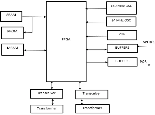
II. CONTROLLER BOARD ARCHITECTURE
applied to the chip and generates reset impulses is given to the FPGA circuit. MIL-STD-1553 bus is used for communication between storing elements and buffers. For remote sensing satellites the controller and DC-DC interface is designed. The controller unit is designed for both main and redundant controller. The RAW bus voltage received by the controller is converted into secondary voltages with the help of DC-DC converter. And the over voltage in the circuit is handled by the OVP (Over Voltage Protection). The EL215 relay driver is used to select the secondary voltages using commands given from FPGA. The MIL-STD-1553 bus communication is used as normal bus communication is complex.
Figure 1:Controller Board Architecture
MEMORY DEVICES: MRAM, PROM, SRAM
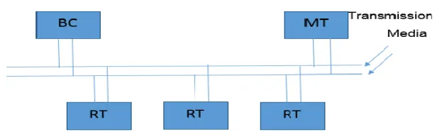
Remote terminal is implemented at Baseband Data Handling (BDH) end. Bus communication media is twisted shielded pair. Using this bus standard bus communication is done as shown in Figure 2.
III.BUSCOMMUNICATION
Figure 2: Bus Communication
2.1 The Standard defines four hardware elements 1. Transmission media (or Data Bus)
2. Bus Controller (BC) 3. Remote Terminal (RT) 4. Monitor Terminal (MT)
Bus Controller Provides data flow control for all transmissions on the Bus. Initiates data transfer on the bus Uses Command/response method. Only one Bus Controller may be active at a time. Remote Terminal capable of transmitting or receiving data on receiving the command from Bus controller. With the use of remote sense signals it will receives the signal and transmits the signals it will be controlled by command from the bus controller. RT uses command word information for processing messages. Total number of available sub address = 60 (30 transmit, 30 receive). Two sub addresses 00000 & 11111 are used to designate mode codes. Total number of data words stored in each sub address = 32. Two types of Remote Terminal Embedded RT Sensor or Subsystem that provides its own internal 1553 interface. Stand Alone RT Used to interface and monitor transmissions in and out of non-1553 subsystems. Monitor Terminal that listens to the exchange of information on the data bus and Collects data from data bus. Providing information to backup Bus Controller to take over as the Bus Controller. The standard specifies two methods for a terminal to be connected to the main bus:
1. Direct coupled to main bus 2. Transformer coupled to main bus
Figure 3: Direct Coupled to main bus [5] Figure 4:Transformer Coupled to main bus [5]
IV.VOLTAGESELECTION
Figure 5: Voltage Selection using EL215
REFERENCES
[1] Kraig Mitzer, “PCB Design using OrCAD”, vol. 38, no. 7, pp. 393-422, , 2002.
[2] T.R Yasuda, M. Yamamoto, and T. Nishi,”A power-on-reset pulse generator for low voltage applications,” The 2001 IEEE International Symposium on Circuits and Systems, ISCAS, VOL-IV, pp 598-601.
[3] MIL-STD-1553 Tutorial, Condor Engineering.
[4] SuMMIT Data Sheets of UT69151CDXE5.
![Figure 3: Direct Coupled to main bus [5] Figure 4:Transformer Coupled to main bus [5]](https://thumb-us.123doks.com/thumbv2/123dok_us/1518618.1186085/4.595.79.467.203.427/figure-direct-coupled-main-figure-transformer-coupled-main.webp)
