This study was sponsored by the South Carolina Department of Transportation and the Federal Highway Administration. The opinions, findings and conclusions expressed in this report are those of the authors and not necessarily those of the SCDOT or FHWA. This report does not comprise a standard, specification or regulation.
Department of Civil and
Environmental Engineering
300 Main Street Columbia, SC 29208S
PECIFICATIONS FOR
C
ULVERT
P
IPE
USED IN
SCDOT
H
IGHWAY
A
PPLICATIONS
S
ARAHL.
G
ASSMAN,
P
H.D.
SUBMITTED TO
T
HES
OUTHC
AROLINAD
EPARTMENT OFT
RANSPORTATION ANDT
HEF
EDERALH
IGHWAYA
DMINISTRATIONO
CTOBER2005
1. Report No.
FHWA-SC-05-07
2. Government Accession No. 3. Recipient’s Catalog No.
5. Report Date
October 2005 (Revised March 2006)
4. Title and SubtitleSpecifications for Culvert Pipe used in SCDOT Highway
Applications
6. Performing Organization Code7. Author(s)
S.L. Gassman
8. Performing Organization Report No 9. Performing Organization Name and Address
Department of Civil and Environmental Engineering
University of South Carolina
300 Main Street
Columbia, SC 29208
10. Work Unit No. (TRAIS)
11. Contract or Grant No.
SPR 625
12. Sponsoring Agency Name and Address
South Carolina Department of Transportation
955 Park Street, PO Box 191
Columbia, SC 29202
14. Sponsoring Agency Code
15. Supplementary Notes
Prepared in cooperation with the Federal Highway Administration
16. AbstractThis report presents the findings from a study undertaken to improve the field
performance and service life of reinforced concrete, aluminum alloy and high density
polyethylene culvert pipe used in SCDOT roadway applications. The work resulted in the
development of a “SCDOT Culvert Pipe Selection Guide” which provides a step by step
procedure for selecting pipe materials for specific applications. The criteria for pipe selection
include durability, hydraulic capacity, structural capacity, service life, compatibility of pipe
material to site conditions and life cycle costs. Guidance is provided on the recommended
practices for proper design, installation and quality control/quality assurance for product
approval and field inspection of delivered pipe and installation procedures. Recommendations
were made to modify the SCDOT Standard Specifications for Highway Construction and other
SCDOT documents to properly address the design, installation and inspection of culvert pipe.
The final product of this work was the development of a training course to educate SCDOT
personnel on the proper design, installation, maintenance, and quality control/quality assurance
of culvert pipe used in roadway applications.
17. Key Words
Culvert Pipe, Concrete Pipe, High Density
Polyethylene Pipe, Aluminum Pipe
18. Distribution Statement
No restriction.
19. Security Classif. (of this report)unclassified
20. Security Classif. (of this page)
unclassified
21. No. of Pages
87
22. Price
The content of this report reflects the views of the authors who are responsible for the findings and conclusions presented herein. The contents of this report do not necessarily reflect the views of the South Carolina Department of Transportation or the Federal Highway Administration. This report does not constitute a standard, specification or regulation.
ACKNOWLEDGEMENTS
This research was funded by the South Carolina Department of Transportation and the Federal Highway Administration. Their support is greatly appreciated. The author would like to acknowledge the following students for their contribution to this investigation: Evangelia Leon, Chetana Kommireddi, Erin Atkins, and Shanna Neill.
EXECUTIVE SUMMARY
This report presents the findings from a study undertaken to improve the field performance of culvert pipe used in SCDOT roadway applications. Reinforced concrete, corrugated aluminum alloy and high density polyethylene pipe are the primary pipe materials used on SCDOT projects. Appropriate use of these pipe materials in terms of design, installation, maintenance, service life, and quality control/quality assurance was the focus of the study. The research involved reviewing research manuscripts, AASHTO and ASTM specifications, construction standards and specifications of state transportation departments, and manufacturer’s literature. The work resulted in the development of a “SCDOT Culvert Pipe Selection Guide” which provides a step by step procedure for selecting pipe materials for specific applications. The criteria for pipe selection include durability, hydraulic capacity, structural capacity, service life, compatibility of pipe material to the environmental site conditions and life cycle costs. Guidance is provided on the recommended practices for materials, materials management, installation (backfill materials, trenching, bedding, laying pipe, backfilling, and cover heights), design, maintenance, quality control/quality assurance for product approval and field inspection of delivered pipe and installation procedures. Recommendations made to improve the installation of all culvert pipe include improving the quality and density of backfill materials placed around pipe, improving the compaction inspection standards by performing density checks on compacted backfill at the spring line of the pipe to ensure that compaction is adequate in the haunches, requiring a minimum compaction level of 95% Standard Proctor density, and requiring all pipe to meet minimum cover requirements. Recommendations made to improve the inspection standards for all installed pipes include visually inspecting all pipes after installation to ensure proper joining, line and grade of pipe. Large diameter pipe should be inspected by walking the length of the pipe; whereas small diameter pipes require the use of video camera equipment with a laser deflection measuring device attached. Random inspections of pipe should be made throughout the construction process to prevent poor construction methods from propagating through entire projects. The study also recommends utilizing third party certification and testing programs for quality control and quality assurance. The final product of this work was the development of a training course to educate SCDOT personnel on the proper design, installation, maintenance, and quality control/quality assurance of culvert pipe used in roadway applications.
TABLE OF CONTENTS PAGE # ACKNOWLEDGEMENTS iii EXECUTIVE SUMMARY iv TABLE OF CONTENTS v SICONVERSION FACTORS vi 1.0 INTRODUCTION 1-1 1.1BACKGROUND 1-1 1.2RESEARCH OBJECTIVES 1-2 1.3REPORT OUTLINE 1-2
2.0 CULVERT PIPE SELECTION GUIDE 2-1
3.0 GUIDANCE FOR INSTALLATION OF CULVERT PIPE ON SCDOTPROJECTS 3-1
3.0.1MATERIALS 3-1
3.0.2MATERIAL MANAGEMENT 3-1
3.0.3INSTALLATION 3-2
3.0.4INSTALLATION INSPECTION 3-8
3.0.5MAINTENANCE 3-10
3.1 INSTALLATION OF HDPEPIPE 3-11
3.1.1MATERIALS 3-11
3.1.2MATERIAL MANAGEMENT 3-12
3.1.3INSTALLATION 3-13
3.1.4INSTALLATION INSPECTION 3-13
3.2 INSTALLATION OF CONCRETE PIPE 3-15
3.2.1MATERIALS 3-15
3.2.2MATERIAL MANAGEMENT 3-15
3.2.3INSTALLATION 3-16
3.2.4INSTALLATION INSPECTION 3-17
3.3 INSTALLATION OF ALUMINUM PIPE 3-18
3.3.1MATERIALS 3-18
3.3.2MATERIAL MANAGEMENT 3-20
3.3.3INSTALLATION 3-20
3.3.4INSTALLATION INSPECTION 3-21
4.0 THIRD PARTY CERTIFICATION PROGRAMS 4-1
4.1THIRD PARTY CERTIFICATION PROGRAMS FOR HDPEPIPE 4-1
4.2THIRD PARTY CERTIFICATION PROGRAMS FOR CONCRETE PIPE 4-5 4.3THIRD PARTY CERTIFICATION PROGRAMS FOR ALUMINUM PIPE 4-6
5.0 LIFE CYCLE COST ANALYSIS 5-1
5.1 STANDARD METHODOLOGY 5-1
5.2 PRELIMINARY ANALYSIS 5-2
5.3 NEED FOR DATA ON REPAIR AND MAINTENANCE COSTS 5-2
6.0 TRAINING COURSES 6-1
7.0 PROJECT SUMMARY 7-1
7.1RECOMMENDATIONS 7-1
7.2SUGGESTED REVISIONS TO SECTION 714 OF THE SCDOTSTANDARD SPECIFICATIONS
FOR CONSTRUCTION 7-3
8.0 BIBLIOGRAPHY 8-1
SICONVERSION FACTORS
SI* (MODERN METRIC) CONVERSION FACTORS
APPROXIMATE CONVERSIONS TO SI UNITS APPROXIMATE CONVERSIONS FROM SI UNITS Symbol When You
Know Multiply By To Find Symbol Symbol
When You Know Multiply By To Find Symbo l LENGTH LENGTH
In inches 25.4 millimeters mm mm millimeters 0.039 inches in
Ft feet 0.305 meters m m meters 3.28 feet ft
Yd yards 0.914 meters m m meters 1.09 yards yd
Mi miles 1.61 kilometers km km kilometers 0.621 miles mi
AREA AREA
in2 square inches 645.2 square
millimeters mm 2 mm2 square millimeters 0.0016 square inches in 2
ft2 square feet 0.093 square meters m2 m2 square meters 10.764 square feet ft2 yd2 square yards 0.836 square meters m2 m2 square meters 1.195 square yards yd2
Ac acres 0.405 hectares ha ha hectares 2.47 acres ac
mi2 square miles 2.59 square kilometers km2 km2 square kilometers 0.386 square miles mi2
VOLUME VOLUME
fl oz fluid ounces 29.57 milliliters ml ml milliliters 0.034 fluid ounces fl oz
Gal gallons 3.785 liters l l liters 0.264 gallons gal
ft3 cubic feet 0.028 cubic meters m3 m3 cubic meters 35.71 cubic feet ft3 yd3 cubic yards 0.765 cubic meters m3 m3 cubic meters 1.307 cubic yards yd3 NOTE: Volumes greater than 1000 l shall be shown in m3
MASS MASS
Oz ounces 28.35 grams g g grams 0.035 ounces oz
Lb pounds 0.454 kilograms kg kg kilograms 2.202 pounds lb
T Short tons
(2000 lb) 0.907
megagrams (or “metric ton”)
Mg (or “t”)
Mg (or “t”)
megagrams
(or “metric ton”) 1.103
Short tons (2000 lb) T
TEMPERATURE (exact ) TEMPERATURE (exact)
o
F Fahrenheit 5(F-32)/9 Celsius 0C 0C Celsius 1.8C+32 Fahrenheit oF temperature Or (F-32)/1.8 Temperature Temperature temperature
ILLUMINATION ILLUMINATION
Fc foot-candles 10.76 lux lx lx lux 0.0929 foot-candles fc Fl foot-Lamberts 3.426 candela/m2 cd/m2 cd/m2 candela/m2 0.2919 foot-Lamberts fl
FORCE and PRESSURE or STRESS FORCE and PRESSURE or STRESS
Lbf poundforce 4.45 Newtons N N Newtons 0.225 Poundforce lbf lbf/in2 poundforce per
square inch 6.89 kilopascals kPa kPa kilopascals 0.145
Poundforce per square
inch
lbf/in2
*SI is the symbol for the International System of Units. Appropriate rounding should be made to comply with Section 4 of ASTM E38
1.0 INTRODUCTION
This report presents the findings from a study undertaken to improve the field performance of culvert pipe used in SCDOT roadway applications. Reinforced concrete (RCP), corrugated aluminum alloy (CAAP) and high density polyethylene (HDPE) pipe are the primary pipe materials used on SCDOT projects. Appropriate use of these pipe materials in terms of design, installation, maintenance, service life, and quality control/quality assurance was the focus of the study.
1.1 BACKGROUND
Although corrugated high density polyethylene (HDPE) pipe has been used successfully for decades in a variety of drainage applications, it is relatively new when compared to concrete and aluminum pipe. With all three products having similar hydraulic performance, selection of the pipe material for a project will be based on considerations other than hydraulics, such as strength, durability and cost.
Not much was known about the field performance of HDPE pipe in South Carolina prior to the SCDOT study entitled “Performance of High Density Polyethylene (HDPE) Pipe” (Gassman et al. 2000). The study (herein referred to as “Phase I”) presented results from field investigations of 45 HDPE pipes, primarily used in sideline or driveway applications, throughout South Carolina that were conducted to evaluate both the external and internal pipe conditions. Overall the pipes were performing well, maintaining a relatively round shape with limited structural distress, and were still functioning as originally intended. As such, the study found that HDPE pipe is an acceptable pipe material that can be used on SCDOT maintenance and construction projects when proper installation techniques are followed.
Some pipes inspected in the Phase I study had cracks, localized bulges and excess deformations, yet none of the damage was severe enough to require removal and replacement at the time of investigation. It was clear from the study that the performance of the pipe was significantly influenced by the installation technique. Installation problems such as poor preparation of bedding soils, inappropriate backfill material, and inadequate backfill cover contributed to the excessive deflection and observed internal cracking in pipes with noted damage. Appropriate installation procedures are essential to achieving high quality performance. Therefore, the study recommended the following to improve the performance of HDPE pipe in South Carolina: train maintenance crews in the laying of plastic pipe, follow ASTM and AASHTO installation procedures, inspect pipes after installation, and develop guidelines for HDPE pipe product approval.
In the past few years, the results of many state, federal and industry supported research projects have led to recent changes to AASHTO specifications (AASHTO M294, Section 12 of the AASHTO LRFD Bridge Design Specifications, Section 18 of the Standard Specifications for Highway Bridges, and Section 30 of the Construction Section of both the Standard Specifications for Highway Bridges and the LRFD Bridge Design Specifications). These changes have been made to improve standard design and installation practices as well as material requirements for HDPE pipe. In addition, many state transportation departments have made significant changes to their construction specifications and standards for culvert pipe, and have also updated their drainage manuals.
Even today the subject of culvert pipe performance still remains one of great importance in the transportation community because of the need to improve the performance of all pipe materials used in drainage applications. Koerner (2004), in his paper written for the TRB Transportation in the New Millennium paper, indicated that there are many issues that are still unanswered and need to be researched. Some of these include: How to guarantee acceptable drainage during a service lifetime? What maintenance commitments and training are needed to ensure adequate performance? How to formulate specifications to ensure the adequacy of specific products and materials? How to best define and quantify life-cycle costs and subsequent performance? While the results of this study and studies by others are beginning to answer these questions, future research is necessary to fully understand how to design and install culvert pipe to achieve optimum performance, and how to guarantee the projected service life. Therefore, it is recommended that the SCDOT consider the recommendations and guidance in this report and implement as deemed necessary. Then, they should engage in a continuous mode of improvement by updating and revising construction standards, specifications, manuals, etc. as the results of future research become available.
1.2 OBJECTIVE
The overall objective of this work was to provide guidance for SCDOT engineers and maintenance personnel in design, installation, maintenance, and quality control/quality assurance of culvert pipe used in roadway applications. Currently, the SCDOT approves three pipe materials for use in its highways. They are reinforced concrete, aluminum alloy and HDPE pipe which were the focus of the study.
To meet this objective the following work was performed:
1) Reviewed research manuscripts, AASHTO and ASTM specifications, construction standards and specifications used by transportation departments, and manufacturer’s literature on topics including design, installation, maintenance, durability, service life and quality control/quality assurance of reinforced concrete, aluminum and HDPE pipe. 2) Developed a “SCDOT Culvert Pipe Selection Guide” which provides a step by step
procedure for selecting pipe materials for specific applications. The criteria for pipe selection include durability, hydraulic capacity, structural capacity, service life, and compatibility of pipe material to site conditions.
3) Provided guidance on the recommended practices for proper design and installation of reinforced concrete, high density polyethylene and aluminum alloy culvert pipes; including guidance for materials, materials management, installation (backfill materials, trenching, bedding, laying pipe, backfilling, and cover heights), installation inspection, and maintenance.
4) Made recommendations to modify the SCDOT Standard Specifications for Highway Construction to properly address the design and installation of concrete, aluminum and HDPE culvert pipe.
5) Provided guidance for quality control/quality assurance for product approval and material testing and quality control/quality assurance for field inspection of delivered pipe and installation procedures.
6) Evaluated life cycle cost methodology.
7) Developed training/certification courses to educate SCDOT personnel on the proper design, installation, maintenance and quality control/quality assurance of culvert pipe used in roadway applications.
1.3 REPORT OUTLINE
This report is divided into seven sections. Following the brief introduction presented here in Section 1, the “SCDOT Culvert Pipe Selection Guide” is presented in Section 2. The guide outlines a step by step procedure to select the appropriate pipe type(s) for a given project. The evaluation of a pipe material is based on durability, hydraulic capacity, structural capacity, and life cycle cost. Section 3 contains the recommended practices for proper design and installation of reinforced concrete, high density polyethylene and aluminum alloy culvert pipe. Guidance is provided for materials, materials management, installation (backfill materials, trenching, bedding, laying pipe, backfilling, and cover heights), installation inspection, and maintenance. Section 4 presents a summary of the third party certification programs recommended for culvert pipe approval. Section 5 presents an overview of life cycle cost analysis. A summary of the training course objectives and course outlines are presented in Section 6. Finally, the findings of the study are summarized in Section 7. Recommended revisions to Section 714 of the SCDOT Standard Specifications for Highway Construction are provided.
2.0 CULVERT PIPE SELECTION GUIDE
This section contains the recommended pipe usage guide developed in this study for the SCDOT. The “SCDOT Culvert Pipe Selection Guide” was developed based on usage guides from Florida, Georgia, North Carolina, Virginia, West Virginia, Maryland, Utah, Missouri, Kentucky and others.
The guide outlines a step by step procedure to select the appropriate pipe type(s) for a given project. The first step is to determine all the acceptable pipe material types based on use and design life. Next, a hydraulic analysis is performed to estimate required pipe diameter for each acceptable pipe material type. Once the acceptable pipe material types have been determined, then corrosion and abrasion analyses are performed for the estimated pipe diameter based on the environmental conditions (pH, resistivity, chlorides and sulfates) of the soil and water found at the site. Flow velocity is also considered for abrasion resistance. This analysis will result in a list of acceptable pipes that meet environmental service life requirements. The hydraulic analysis is again performed on this new list of acceptable pipes to confirm the diameter estimate in the event that the corrosion and abrasion analyses changed the initial diameter estimates or eliminated one or more of the acceptable pipe material types. The next step is to perform a structural analysis and verify that the depth of backfill is in between the recommended minimum and maximum fill heights. Minimum and maximum cover height tables are included in the guide. The final step is to analyze life cycle costs.
It is important to note that Section 5514 “Competition for Specification of Alternative Types of Culvert Pipes” of the Code of Federal Regulations requires that “…States provide for competition with respect to the specification of alternative types of culvert pipes through requirements that are commensurate with competition requirements for other construction materials….” The guide presented herein outlines a procedure to help meet this federal requirement.
SCDOT
C
ULVERT
P
IPE
S
ELECTION
G
UIDE
The evaluation of a pipe material is based on durability, hydraulic capacity, structural capacity, and life cycle cost.
Methodology:
1) Determine acceptable pipe material types based on use and design life.
2) Perform hydraulic analysis to estimate required pipe diameter for each acceptable pipe type. 3) Perform corrosion and abrasion analysis for the estimated pipe diameter based on environmental conditions of soil and water.
4) Obtain list of acceptable pipes that meet environmental service life requirements. 5) Perform hydraulic analysis to confirm diameter estimate.
6) Perform structural analysis. Verify that depth of backfill meets the minimum and maximum fill height requirements.
7) Analyze life cycle costs.
ACCEPTABLE PIPE MATERIAL TYPES BASED ON USE AND DESIGN LIFE:
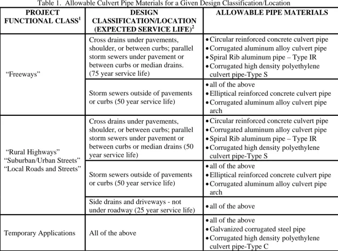
The first step is to determine the allowable culvert pipe materials for a given design classification or location using Table 1. The overall service life of a pipeline is a function of the pipe material, the environmental site conditions and the installation of the pipe. The material properties of the pipes on this list meet the desired service life requirements as noted in the table. Further analysis is required to determine if these pipes meet the environmental service life requirements as outlined in Step 3. In addition, analysis should consider the recommended minimum backfill soil conditions noted in Table 1.
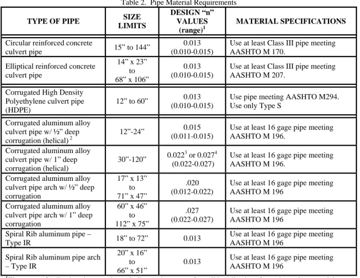
The pipe material requirements (size limits and material specifications) for each pipe type are shown in Table 2.
HYDRAULICS:
The second step is to perform hydraulic analysis to estimate the required pipe diameter for each acceptable pipe material type. The designer should use Table 2 when assigning a Manning’s “n” value for the various culvert pipe options allowed for a given roadway classification. Recommended design values should be used unless the engineer has a justifiable reason for selecting a different value from the range of acceptable values. If more than one material type is acceptable for a given project, more than one hydraulic design may be required: one using a Manning’s roughness coefficient (n=0.13) associated with concrete, spiral rib, and polyethylene pipe and one using a Manning’s roughness coefficient associated with corrugated aluminum alloy pipe.
Table 1. Allowable Culvert Pipe Materials for a Given Design Classification/Location PROJECT
FUNCTIONAL CLASS1
DESIGN
CLASSIFICATION/LOCATION (EXPECTED SERVICE LIFE)2
ALLOWABLE PIPE MATERIALS
Cross drains under pavements, shoulder, or between curbs; parallel storm sewers under pavement or between curbs or median drains. (75 year service life)
•Circular reinforced concrete culvert pipe •Corrugated aluminum alloy culvert pipe •Spiral Rib aluminum pipe – Type IR •Corrugated high density polyethylene
culvert pipe-Type S “Freeways”
Storm sewers outside of pavements or curbs (50 year service life)
•all of the above
•Elliptical reinforced concrete culvert pipe •Corrugated aluminum alloy culvert pipe
arch Cross drains under pavements,
shoulder, or between curbs; parallel storm sewers under pavement or between curbs or median drains (50 year service life)
•Circular reinforced concrete culvert pipe •Corrugated aluminum alloy culvert pipe •Spiral Rib aluminum pipe – Type IR •Corrugated high density polyethylene
culvert pipe-Type S Storm sewers outside of pavements
or curbs (50 year service life)
•all of the above
•Elliptical reinforced concrete culvert pipe •Corrugated aluminum alloy culvert pipe
arch “Rural Highways”
“Suburban/Urban Streets” “Local Roads and Streets”
Side drains and driveways - not
under roadway (25 year service life) •all of the above Temporary Applications All of the above
•all of the above
•Galvanized corrugated steel pipe •Corrugated high density polyethylene
culvert pipe-Type C
1
Project function class is defined by the SCDOT Highway Design Manual (2003).
2
Expected service life is a function of 1) pipe material and 2) installation; therefore, as further discussed in Section 3.0.3.1, applications that require at least a 75 year service life (freeways) shall use a well-graded sand or gravel meeting the requirements of GW or SW material (ASTM 2487) or A-1 (AASHTO M 145)) for the bedding and backfill. Uniformly graded coarse-grained soils (GP, SP and A-3) can be used if provisions are made to evaluate and control possible migration of fines into open voids. Backfill shall be compacted to at least 95% of maximum standard Proctor density per AASHTO T 99.
Conduits under roadways having a 50 year service life (rural highways, suburban and urban streets, local roads and streets) shall use the requirements for a 75 year service life or shall use coarse grained soils with fines or fine grained soils with at least 50% coarse grained material and low to no plasticity (GC, GM, SC, SM, A-2-4 and A-2-5) if compaction requirements are strictly enforced. Backfill shall be compacted to at least 95% of maximum standard Proctor density per AASHTO T 99.
Storm sewers outside of pavements (50 year service life) or applications that require a 25 year service life (side drains, driveways and conduits outside of pavements) may use any of the materials above as well as fine grained soils with low to medium plasticity (CL, ML, GC, SC or A-2-6, A-2-7, A-5, A-6) compacted to at least 95% of maximum standard Proctor density per AASHTO T 99.
Table 2. Pipe Material Requirements
TYPE OF PIPE SIZE
LIMITS
DESIGN “n” VALUES
(range)1
MATERIAL SPECIFICATIONS Circular reinforced concrete
culvert pipe 15” to 144”
0.013 (0.010-0.015)
Use at least Class III pipe meeting AASHTO M 170.
Elliptical reinforced concrete culvert pipe 14” x 23” to 68” x 106” 0.013 (0.010-0.015)
Use at least Class III pipe meeting AASHTO M 207.
Corrugated High Density Polyethylene culvert pipe (HDPE)
12” to 60” 0.013 (0.010-0.015)
Use pipe meeting AASHTO M294. Use only Type S
Corrugated aluminum alloy culvert pipe w/ ½” deep corrugation (helical) 2
12”-24” 0.015 (0.011-0.015)
Use at least 16 gage pipe meeting AASHTO M 196.
Corrugated aluminum alloy culvert pipe w/ 1” deep corrugation (helical)
30”-120” 0.022
3
or 0.0274 (0.022-0.027)
Use at least 16 gage pipe meeting AASHTO M 196.
Corrugated aluminum alloy culvert pipe arch w/ ½” deep corrugation 17” x 13” to 71” x 47” .020 (0.012-0.022)
Use at least 16 gage pipe meeting AASHTO M 196
Corrugated aluminum alloy culvert pipe arch w/ 1” deep corrugation 60” x 46” to 112” x 75” .027 (0.022-0.027)
Use at least 16 gage pipe meeting AASHTO M 196
Spiral Rib aluminum pipe –
Type IR 18” to 72” 0.013
Use at least 16 gage pipe meeting AASHTO M 196
Spiral Rib aluminum pipe arch – Type IR
20” x 16” to 66” x 51”
0.013 Use at least 16 gage pipe meeting AASHTO M 196
1
The range of “n” values in parentheses indicates the range of possible “n” values for a given pipe material. Variation is due to pipe size and source of published data. The recommended value for use in design is given as the “design “n” value”.
2
Pipes 30” to 72” with ½” corrugation are also available.
3
Based on St. Anthony Falls Hydraulic Laboratory data (used by US Aluminum and Steel)
4
CORROSION:
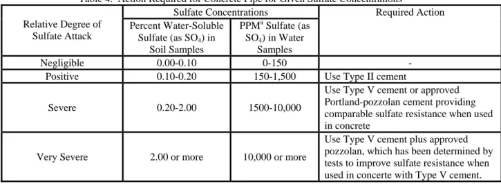
The designer should obtain pH, resistivity and sulfate content data of the soil and water for pipe locations. Equipment to determine these parameters is maintained by the SCDOT Office of Materials and Research. When this data is not obtained, the designer shall take a conservative approach in the specifying of pipe materials. The designer can also refer to soil maps. Maps showing the variation of soil pH by County can be found at www.genglab.ucdavis.edu/ding/zeneca/sc_index.htm. Corrosion resistant material should be used in areas where there is a past history of corrosive water and soil. The type of culvert pipe material specified should only be used within the allowable environmental limits presented in Table 3 unless additional methods of protection are provided. Sulfate concentration is also a durability concern for concrete. Table 4 illustrates the actions required for a given sulfate concentration.
Table 3. Allowable Environments of pH and Resistivity Recommended Environments Material
Soil1 & Water pH Minimum Soil & Water Resistivity (ohm - cm)
Reinforced Concrete Pipe 4 to 9 10002
HDPE Pipe 1.5 to 12 -
Aluminum Alloy 4 to 9 500
1Asphalt coatings are good soil side protection and can be used to lower the pH range by 1, provided there is low ground water, the water pH and resistivities are as outlined above and the joint is water tight (leakage from silt-tight joints can cause an artificial ground water condition).
2A resistivity of less than 1,000 is an indication of the presence of chlorides. As chlorides can attack the reinforcing steel, the reinforcing steel should be epoxy coated if the resistivity is less than 1,000.
Table 4. Action Required for Concrete Pipe for Given Sulfate Concentrations Sulfate Concentrations Relative Degree of Sulfate Attack Percent Water-Soluble Sulfate (as SO4) in Soil Samples PPMa Sulfate (as SO4) in Water Samples Required Action Negligible 0.00-0.10 0-150 -
Positive 0.10-0.20 150-1,500 Use Type II cement
Severe 0.20-2.00 1500-10,000
Use Type V cement or approved Portland-pozzolan cement providing comparable sulfate resistance when used in concrete
Very Severe 2.00 or more 10,000 or more
Use Type V cement plus approved pozzolan, which has been determined by tests to improve sulfate resistance when used in concerte with Type V cement.
a
ABRASION:
The designer should assess the abrasion potential for culvert pipe installations. The slope of the stream and the size of the stream bed material should be considered. The velocity of the flow in the channel upstream of the culvert pipe and in the culvert pipe should be calculated to determine if the abrasives could be transported at a sufficient velocity to cause damage to the invert of the conduit. A frequent storm velocity (Q2 velocity or five year design velocity, v) shall be used to determine abrasion potential. The designer should consider abrasion of the culvert invert as well as flow capacity and sediment transport in establishing the slope of the culvert. Where low bed loads are present (“i.e.” a closed system such as a storm sewer), higher velocities are not of concern. The necessary adjustments for various abrasion levels are shown in Table 5. Note that high velocity systems can create a number of problems including scour of outlets, manholes, catch basins and junction boxes, and require a special design.
Table 5. Invert Protection Chart for Abrasive Flows ABRASION LEVEL (Typical Storm Design Velocity, v) MATERIAL Low Abrasion (v = 0 to 5 fps) Mild Abrasion (v = 5 to 10 fps) Moderate Abrasion (v = 10 to 15 fps) Severe Abrasion (v > 15 fps) Reinforced Concrete Pipe No Addition No Addition No Addition
At least 2” concrete cover over reinforcing steel HDPE Pipe No Addition No Addition No Addition No Addition Aluminum Alloy No Addition No Addition Add one gage Add one gage &
paved invert
STRUCTURE:
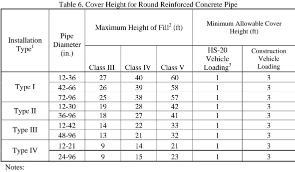
The maximum cover and minimum cover for all pipes are found in Tables 6 through 10. The fill heights are conservative. The designer may exceed the limits set if the pipe is designed in accordance with appropriate AASHTO Design standards from the Standard Specification for Highway Bridges, American Association of State Highway and Transportation Officials, Washington D.C., 2002 or the new AASHTO LRFD Bridge Design Specifications, American Association of State Highway and Transportation Officials, Washington D.C., 2005, as stated in Table 11.
Minimum fill height for all types of pipe is measured from the top of the pipe to the top of soil backfill, excluding any prepared stone base or pavement. All pipes should meet minimum cover requirements and should not be used under roadways when these minimum cover heights cannot be achieved. In some driveway applications, it may be difficult to achieve minimum cover. In these situations, every effort should be made to achieve minimum cover and any deviations from the minimum requirements will require prior approval from
the responsible SCDOT engineer. Concrete elliptical pipe and aluminum pipe arch are good alternatives to circular pipe when additional room for cover is needed.
During construction of pipe culverts, a greater minimum fill height is required. No heavy construction equipment shall be driven over any pipe culvert until the backfill is completed to the minimum allowable cover height for construction loading listed in Tables 6 through 10 so that damage does not occur to the pipe. This minimum cover must be maintained until heavy construction equipment usage is discontinued.
Table 6. Cover Height for Round Reinforced Concrete Pipe
Maximum Height of Fill2 (ft) Minimum Allowable Cover Height (ft) Installation
Type1
Pipe Diameter
(in.)
Class III Class IV Class V
HS-20 Vehicle Loading3 Construction Vehicle Loading 12-36 27 40 60 1 3 42-66 26 39 58 1 3 Type I 72-96 25 38 57 1 3 12-30 19 28 42 1 3 Type II 36-96 18 27 41 1 3 12-42 14 22 33 1 3 Type III 48-96 13 21 32 1 3 12-21 9 14 21 1 3 Type IV 24-96 9 15 23 1 3 Notes: 1
Installation Type is per ASTM C 1479 and AASHTO Section 27, Standard Specification for Highway Bridges, Division II: Construction, American Association of State Highway and Transportation Officials, Washington D.C., 2002
2
Maximum fill heights based on American Concrete Pipe Association (ACPA) Charts
3
A minimum height of cover of 9 in. is acceptable if pipe is constructed under a rigid pavement and granular backfill is used.
0.06 0.075 0.105 0.135 0.164 (16) (14) (12) (10) (8) 12 0.8 113 142 - - - 1 4 15 1.2 94 118 - - - 1 4 18 1.8 75 94 - - - 1 4 24 3.1 56 71 99 - - 1 4 30 4.9 52 65 - - - 1 4 36 7.1 43 54 - - - 1 4 42 9.6 36 46 65 - - 1 4 48 12.6 32 40 57 73 - 1 5.5 54 15.9 28 35 50 65 - 1.25 5.5 60 19.6 - 32 45 58 72 1.5 5.5 66 23.8 - 28 41 53 65 1.75 5.5 72 28.3 - 26 37 48 59 1.75 5.5 78 33.2 - 24 34 44 55 2 5.5 84 38.5 - - 31 41 51 2 5.5 90 44.2 - - 29 38 47 2 5.5 96 50.3 - - 27 36 44 2 5.5 102 56.8 - - - 33 41 2 5.5 108 63.6 - - - 31 39 2 5.5 114 70.9 - - - - 37 2 5.5 120 78.5 - - - - 35 2 5.5 Notes:
1. Maximum cover heights based on Standard Specification for Highway Bridges, American Association of State Highway and Transportation Officials, Washington, D.C., 2002. These heights are approximately 2% less than those determined by the LRFD Bridge Design Specifications, 2004.
2. Maximum cover heights are similar to current DOT Dwg 714-2
3. Maximum cover heights based on use of a well-graded granular backfill compacted to 95% standard proctor. 4. Pipes 30" to 72" with 1/2" corrugation are also available
2 2/3"
x
1/2"
Table 7. Cover Heights and Gages for Corrugated Aluminum Circular Pipe
HS-20 Vehicle Loading Construction Vehicle Minimum Cover (ft) Corrugation
Maximum Allowable Cover Height (ft)
Pipe Wall Thickness (Gage)
3 " x 1" Area (sq. ft) Diameter (in.) 0.06 0.075 0.105 0.135 0.06 0.075 0.105 0.135 (16) (14) (12) (10) (16) (14) (12) (10) 18 20 16 9 - - - 1 - - - 3.5 24 27 21 - 7 - - - 1 - - 3.5 30 33 26 - 5 - - - 1 - - 3.5 36 40 31 - - 5 - - - 1 - 4 42 46 36 - - 5 - - - 1.25 - 4 48 53 41 - 8 - - - 1.25 - - 3.5 54 60 46 - 8 - - - 1.25 - - 3.5 60 66 51 - 9 - - - 1.5 - - 3.5 66 73 55 - 10 - - - 1.75 - - 3.5 72 81 59 - 11 - - - 1.75 - - 3.5 78 87 63 - 10 - - - 2 - - 4 84 95 67 - 11 - - - 2 - - 4 90 103 71 - 10 - - - 2 - - 4 96 112 75 - 10 - - - 2 - - 4 Notes:
1. Maximum cover heights based on AASHTO LRFD Bridge Design Specification, 2004 2. Pipes 48 to 60" with 1/2" corrugation are also available
3. Maximum cover heights based on use of a well-graded granular backfill compacted to 95% standard proctor. Equivalent
Diameter (in.)
Maximum Allowable Cover Height (ft)
Minimum Allowable Cover Height for HS-20 Loading (ft)
Pipe Wall Thickness (Gage) Pipe Wall Thickness (Gage) Span
(in.)
Table 7b. Cover Height and Gages for Corrugated Aluminum Pipe-Arch
Minimum Cover During Construction (ft) Corrugation 3 x 1" 2 2/3 x 1/2" Rise (in.)
0.06 0.075 0.105 0.135 0.06 0.075 0.105 0.135 (16) (14) (12) (10) (16) (14) (12) (10) 18 41 57 - - 1 1 - - 3.5 24 30 42 69 - 1 1 1 - 3.5 30 24 33 55 - 1.25 1 1 - 3.5 36 19 27 45 65 1.5 1.25 1 1 3.5 42 - 23 39 55 - 1.5 1.25 1 3.5 48 - - 34 48 - - 1.5 1.25 3.5 54 - - 30 43 - - 1.75 1.25 4 60 - - 46 38 - - 2 1.5 4 66 - - - 35 - - - 1.75 4 72 - - - 31 - - - 2 4 Notes:
1. Maximum cover heights based on AASHTO LRFD Design Specifications, 2004.
2. Maximum cover heights based on use of a well-graded granular backfill compacted to 95% standard proctor.
Construction Vehicle Loading
Table 8. Cover Height and Gages for Ribbed Aluminum Pipe - Type IR Corrugation -3/4"X3/4"X 71/2"
Diameter (in.)
Maximum Allowable Cover Height (ft)
Minimum Allowable Cover Height (ft)
HS-20 Vehicle Loading
Pipe Wall Thickness (Gage) Pipe Wall Thickness (Gage)
0.06 0.075 0.105 0.135 0.06 0.075 0.105 0.135 (16) (14) (12) (10) (16) (14) (12) (10) 18 20 16 17 - - - 1 - - - 3.5 24 27 21 12 - - - 1.25 - - - 3.5 30 33 26 11 - - - 1.5 - - - 3.5 36 40 31 - 10 - - - 1.75 - - 3.5 42 46 36 - - 9 - - - 1.5 - 3.5 48 53 41 - - 8 - - - 1.75 - 4 54 60 46 - - 8 - - - 2 - 4 60 66 51 - - - 9 - - - 1.75 4 Notes:
1. Maximum cover heights based on AASHTO LRFD Design Specifications, 2004.
2. Maximum cover heights based on use of a well-graded granular backfill compacted to 95% standard proctor.
Pipe Wall Thickness (Gage) Span (in.) Rise (in.) Equivalent Diameter (in.)
Maximum Allowable Cover Height (ft)
Minimum Allowable Cover Height for HS-20 Loading (ft)
Table 9. Cover Height and Gages for Ribbed Aluminum Pipe Arch - Type IR Corrugation -3/4"X3/4"X 71/2"
Minimum Cover During Construction
(ft) Pipe Wall Thickness (Gage)
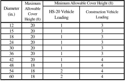
HS-20 Vehicle Loading Construction Vehicle Loading 12 20 1 3 15 20 1 3 18 20 1 3 24 20 1 3 30 20 1 3 36 20 1 3 42 20 1 4 48 18 1 4 54 18 2 4 60 18 2 4 Notes:
1. Recommend minimum Class III Backfill (ASTM D2321), compacted to 95% Standard Proctor Density
2. Maximum cover heights can be increased based on Engineer's review and approval. Table 10. Cover Height for Corrugated High Density Polyethylene Pipe
Minimum Allowable Cover Height (ft) Maximum Allowable Cover Height (ft) Diameter (in.)
REFERENCES SPECIFICATIONS
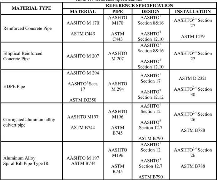
Applicable AASHTO and ASTM reference specifications are summarized in Table 11.
Table 11. Reference Specifications
REFERENCE SPECIFICATION MATERIAL TYPE
MATERIAL PIPE DESIGN INSTALLATION
Reinforced Concrete Pipe
AASHTO M 170 ASTM C443 AASHTO M170 ASTM C443 AASHTO1 Section 8&16 AASHTO3 Section 12.10 AASHTO2,4 Section 27 ASTM 1479 Elliptical Reinforced
Concrete Pipe AASHTO M 207
AASHTO M 207 AASHTO1 Section 8&16 AASHTO3 Section 12.10 AASHTO2,4 Section 27 HDPE Pipe AASHTO M 294 AASHTO1 Sect. 17 ASTM D3350 AASHTO M 294 AASHTO1 Section 17 AASHTO3 Section 12.12 ASTM D 2321 AASHTO2,4 Section 30
Corrugated aluminum alloy culvert pipe AASHTO M197 ASTM B744 AASHTO M196 ASTM B745 AASHTO1 Section 12 AASHTO3 Section 12.7 ASTM B790 AASHTO2,4 Section 26 ASTM B788 Aluminum Alloy Spiral Rib Pipe Type IR
AASHTO M 197 ASTM B744 AASHTO M196 ASTM B745 AASHTO1 Section 12 AASHTO3 Section 12.7 ASTM B790 AASHTO2,4 Section 26 ASTM B788 1
Reference: Standard Specifications for Highway Bridges, Division I: Design, American Association of State Highway and Transportation Officials, Washington D.C., 2002
2
Reference: Standard Specifications for Highway Bridges, Division II: Construction, American Association of State Highway and Transportation Officials, Washington D.C., 2002
3
Reference: AASHTO LRFD Bridge Design Specifications, American Association of State Highway and Transportation Officials, Washington D.C., 2004
4
Reference: AASHTO LRFD Bridge Construction Specifications, American Association of State Highway and Transportation Officials, Washington D.C., 2004
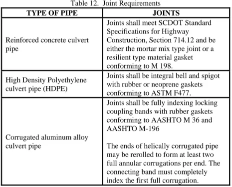
JOINTS:
Joint requirements are summarized in Table 12. Minimum joint performance is “soil tight” for all storm drains, cross drains and side drains. “Soil tight” joints must be watertight to 2 psi. Pipe joints shall be sealed in a manner appropriate to the pipe material. Comply with manufacturer’s recommendations for connecting pipes to concrete headwalls, catch basins, and similar structures.
When installing pipe in fine sands, the tightest joint possible should be used. Joints should be wrapped with a geosynthetic fabric to prevent fine sands from running through joints into the pipe.
Table 12. Joint Requirements
TYPE OF PIPE JOINTS
Reinforced concrete culvert pipe
Joints shall meet SCDOT Standard Specifications for Highway
Construction, Section 714.12 and be either the mortar mix type joint or a resilient type material gasket conforming to M 198. High Density Polyethylene
culvert pipe (HDPE)
Joints shall be integral bell and spigot with rubber or neoprene gaskets conforming to ASTM F477.
Corrugated aluminum alloy culvert pipe
Joints shall be fully indexing locking coupling bands with rubber gaskets conforming to AASHTO M 36 and AASHTO M-196
The ends of helically corrugated pipe may be rerolled to form at least two full annular corrugations per end. The connecting band must completely index the first full corrugation.
Note: The AASHTO Subcommittee on Materials is currently evaluating various joint requirements. The SCDOT should consider their recommendations when they are made.
LIFE CYCLE COSTS
The final step is to analyze life cycle costs. The analysis should include the cost of initial construction and future costs for maintenance, repair, rehabilitation and replacement over the project service life. Guidance for life cycle cost analysis is found in ASTM C1131, ASTM F1675 and ASTM A930 for reinforced concrete, high density polyethylene, and aluminum alloy pipe, respectively. The US Army Corp of Engineers’ (1998) document entitled “Engineering Design: Conduits, Culverts and Pipes” provides additional guidance. To facilitate life cycle cost analysis, the methodology in ASTM C1131 has been incorporated into software entitled “Pipe Pac-2000” by the American Concrete Pipe Association (ACPA).
3.0 GUIDANCE FOR INSTALLATION OF CULVERT PIPE ON SCDOTPROJECTS
The primary AASHTO resources for design and installation of culvert pipe include AASHTO’s Standard Specification for Highway Bridges, Division I: Design and Division II: Construction (2002) and the LRFD Bridge Design Specifications (2004). Text books on the subject include: “Buried Pipe Design” (Moser, 2001), and “Structural Mechanics of Buried Pipes” (Watkins and Anderson, 2000). In addition, a general overview of design and installation of buried pipe can be obtained through a video and accompanying resource book entitled “Design and Installation of Buried Pipes” (McGrath and Howard, 1998) published by ASCE.
The recommendations presented in this section were formulated from the above resources, AASHTO and ASTM specifications, and a review of construction specifications used by transportation departments in Florida, North Carolina, Missouri, Ohio, Utah, New York, West Virginia, Virginia, Maryland and others. The SCDOT should review the recommendations below and modify Section 714 of the current SCDOT Standard Specifications for Highway Construction and other documents as deemed necessary. Some example recommended changes to Section 714 are provided in Section 7.2.
Note that the recommendations in this section primarily apply to SCDOT applications that require at least a 75 year service life (freeways) or other conduits under roadways having a 50 year service life (rural highways, suburban and urban streets, local roads and streets) as outlined in the “SCDOT Culvert Pipe Selection Guide” developed in this project. Storm sewers outside of pavements (50 year service life) or applications that require a 25 year service life (side drains, driveways and conduits outside of pavements) may require less stringent specifications in some cases.
Section 3.0 contains discussion and recommendations that are applicable to all pipe material types. Specific recommendations for HDPE, reinforced concrete and aluminum alloy pipe are presented in Sections 3.1, 3.2 and 3.3, respectively.
3.0.1 Materials
Allowable pipe materials include reinforced concrete, high density polyethylene and aluminum alloy. Circular reinforced concrete pipe (conforming to AASHTO M 170), high density polyethylene pipe-Type S (AASHTO M 294) and corrugated aluminum alloy pipe and spiral rib aluminum pipe-Type IR (AASHTO M 196) are allowed for use on all project types as shown in Table 1 of the “SCDOT Culvert Pipe Selection Guide.” Galvanized corrugated steel pipe and high density polyethylene pipe-Type C are only allowed for temporary applications.
3.0.2 Material Management
Handling. Culvert pipe must be handled and stored in such a way that no damage occurs to the pipe. Pipes, fittings and other components must be lifted and moved safely with the aid of appropriate unloading and handling equipment. Room must be sufficient to allow for handling equipment to get around the piping components.
Inspection. The pipe should be inspected at the time of delivery to verify that the correct products and the expected quantities are received, and that they arrived in good condition and ready for installation. Pipe walls and corrugations, gaskets, pipe ends, couplers or other joints, and accessories should be visually inspected for damage that may have occurred during shipment. Pipe should be checked to ensure it has the correct markings to indicate that it meets specification.Any damage, missing packages, incorrect product, etc., should be noted on the bill of lading at the time of shipment, and reported to the product supplier immediately.
Storage. The unloading site must be relatively flat and level, free of debris, and out of the way of construction traffic. The base row must be blocked to prevent sideways movement or shifting.
3.0.3 Installation
Those persons installing pipe must be familiar with the general zones of the pipe soil envelope (foundation, bedding, haunch area, embedment and backfill) as shown in Figure 3.1 and the appropriate materials and levels of compaction required for each as specified in ASTM and AASHTO standards (see Table 11 in the “SCDOT Culvert Pipe Selection Guide”). Note that the specific trench terminology used in each AASHTO and ASTM standard for each pipe type varies slightly. Proper installation will improve the performance of all pipe used on SCDOT projects and will assure that the service life expected is obtained. A qualified engineer should be engaged to design a proper foundation, adequate bedding and backfill.
Figure 3.1 Standard Trench Terminology (after McGrath and Howard, 1998) FOUNDATION BEDDING HAUNCH AREA TRENCH WALLS IN SITU SOIL BACKFILL EMBEDMENT (Height Varies)
In general, the construction sequence should be as follows: 1. Place bedding material to grade, compact.
2. Carefully shape the trench bottom to fit the bottom of the pipe for a depth of a least 10% of its overall height.
3. Install pipe to line and grade.
4. Place and compact the haunch area of the pipe.
5. Place and compact soil in lifts up to the spring line of the pipe.
6. Complete backfilling. Backfill should be compacted in lifts to the required density. If native soil on trench bottom is suitable for bedding, the construction sequence should be as follows:
1. Carefully shape the trench bottom to fit the bottom of the pipe for a depth of a least 10% of its overall height.
2. Install pipe to grade.
3. Place and compact the haunch area of the pipe.
4. Place and compact soil in lifts up to the spring line of the pipe.
5. Complete backfilling. Backfill should be compacted in lifts to the required density. In both cases, bedding shall have recesses shaped to fit any projected hubs or bells.
3.0.3.1 Backfill Materials
Soils are commonly classified using the Unified Soil Classification System (ASTM D 2487) or the AASHTO Soil Classification System (AASHTO M 145). In addition, ASTM D2321 divides the soils into different “Classes.” The equivalent ASTM and AASHTO Soil Classifications are shown in Table 3.1.
Table 3.1 Equivalent ASTM and AASHTO Soil Classifications
Basic Soil Type ASTM D 2487 AASHTO M 145 ASTM D 2321 Sn
(Gravelly sand)
SW, SP, GW, GP
Sands and gravels with 12% or less fines
A-1, A-3 Class IB: Manufactured, processed aggregates; dense graded, clean
Class II: Coarse-grained soils, clean
Si
(Sandy silt)
GM, SM, ML
Also GC and SC with less than 20% passing a No. 200 sieve
A-2-4, A-2-5, A4 Class III: Coarse-grained soils with fines
Class IVA: Fine-grained soils with no to low plasticity
Cl
(Silty clay)
CL, MH, GC, SC
Also GC and SC with more than 20% passing a No. 200 sieve
A-2-6, A-2-7, A-5, A-6 Class IVA: Fine-grained soils with low to medium plasticity
Use of sands and gravels for the structural backfill (bedding, haunch and embedment) will provide the greatest assurance of good performance. Sands and gravels without fines achieve good densities when dumped and excellent densities when compacted. If placed, spread and compacted in moderate lift thicknesses, excellent pipe support is assured for all typical installations. The materials provide excellent pipe performance when placed and compacted and are less sensitive to poor construction practices than other materials.
The preferred structural backfill is a well-graded sand or gravel meeting the requirements of GW or SW material (ASTM D 2487) or A-1 or A-3 (AASHTO M 145) or Classes IB and II (ASTM D 2321). Note that pea gravel is excluded from allowable gravels. Uniformly graded coarse-grained soils (GP and SP per ASTM D2487 and A-3 per AASHTO) also provide good service but are not recommended unless provisions are made to evaluate and control possible migration of fines into open voids. Coarse-grained soils with fines (GC, GM, SC, SM (ASTM D 2487) or A-2-4 or A-2-5 (AASHTO M 145) or Class III (ASTM D 2321)) or fine grained soils with at least 50% coarse grained material (sandy silts and sandy clays) provide good performance when properly placed and compacted, but are more susceptible to problems if good construction practices are not executed; therefore when using these materials, increased inspection during construction is recommended. Low plasticity silts and clays meeting the requirements of ML or CL material (ASTM D 2487) or 2, 4, A-5, or A-6 (AASHTO M 145) or Class IVA (ASTM D 2321) should not be used because they are difficult to properly compact in the field. If these soils are used, compaction must be closely monitored to ensure that the soil is at or near the optimum moisture content (within ±2%) and the appropriate compactive effort is used. Organics, peats, and highly plastic clays and silts (CH, MH or Class IVB) are not acceptable.
Therefore, it is recommended for SCDOT applications that require at least a 75 year service life (“freeways” as defined by the SCDOT Highway Design Manual (2003)) shall use a well-graded sand or gravel meeting the requirements of GW or SW material (ASTM 2487) or A-1 (AASHTO M 145)) for the bedding and backfill. Uniformly graded coarse-grained soils (GP, SP and A-3) can be used if provisions are made to evaluate and control possible migration of fines into open voids.
Conduits under roadways having a 50 year service life (“rural highways”, “suburban and urban streets,” “local roads and streets” as defined by the SCDOT Highway Design Manual (2003)) shall use coarse grained soils with fines or fine grained soils with at least 50% coarse grained material and low to no plasticity (GC, GM, SC, SM, A-2-4 and A-2-5) if compaction requirements are strictly enforced. Backfill shall be compacted to at least 95% of maximum standard Proctor density per AASHTO T 99.
Storm sewers outside of pavements (50 year service life) or applications that require a 25 year service life (side drains, driveways and conduits outside of pavements) may use any of the materials above as well as fine grained soils with low to medium plasticity (CL, ML, GC, SC or A-2-6, A-2-7, A5, A6) compacted to at least 95% of maximum standard Proctor density per AASHTO T 99.
Whenever possible, native soils should be used as backfill materials to minimize cost. Native soils in South Carolina range from sands and gravelly sand in the Coastal Plain Region to low plasticity clays in the Piedmont and Blue Ridge Regions. Native soils classified as low plasticity silts and clays meeting the requirements of ML or CL material (ASTM D 2487) or A-2, A-4, A-5, or A-6 (AASHTO M 145) or Class IVA
(ASTM D 2321) can be blended with select materials to make a suitable backfill material. When compacting native fine grained soils, the moisture content and compactive effort must be closely monitored to ensure adequate compaction. In areas where appropriate backfill and bedding materials are not available, select materials must be specified and used.
Material used for bedding and backfill shall not contain rocks, frozen lumps, chunks of highly plastic clay, organic material such as tree roots, or other deleterious material. These materials can cause point loads on the pipe or decompose to create voids.
One alternative to specifying coarse-grained backfill materials is to specify a flowable fill. Controlled low strength material (CLSM) and controlled density fill (CDF) are flowable fills which may be used for bedding and backfill. The mixture design should be specified so that the material is excavatable after it reaches full strength. Restraint must be provided to prevent flotation of any pipe type.
3.0.3.2 Trenching
The trench shall be excavated on line and after excavating the trench the bedding shall be placed to the proper thickness to establish the grade. Proper alignment is established by field survey. The top of the bedding should be adjusted to allow for the difference between the plan invert (flowline) and pipe profile wall thickness. The sidewalls of a trench must remain stable throughout construction. Trenches should be left open for the least possible time because they may destabilize, flood, freeze or become a safety hazard. In some cases a moveable trench box may be needed to provide a safe working area by preventing the side walls from caving in. The trench box must be moved with care to avoid damaging the pipe or disturbing the compacted soil. Comply with all Occupation Safety and Health regulations when excavating and trenching. Note that there are safety restrictions for trenches deeper than 4 feet. Workers in the trench must stay within the trench box when utilized.
Trench dimensions depend on site conditions, the soil encountered, the type of pipe and its size and shape. The trench width must be wide enough to allow joining pipe and proper placement and compaction of the backfill. For rigid pipe, the trench should only be as wide as necessary to properly compact the backfill around the pipe. For flexible pipe, the side support comes from the combined stiffness of the trench wall and the embedment soil. Therefore, if the trench wall soil is stronger than the embedment soil, minimum space is needed. If trench walls are soft and weak, a greater width of compacted embedment or stronger embedment soil is needed. As a guide, the AASHTO LRFD Bridge Design Specifications (2004), Section 12, recommends that the minimum trench width should not be less than the greater of the pipe diameter plus 18 in. or the pipe diameter times 1.5 plus 12 in.
The trench foundation provides the base for the bedding material and must provide uniform, stable support for the pipe. Soils for the foundation may consist of the native soil or a modification. Organic material or soft or low density soil is not suitable because it can cause differential settlement. Very soft, wet soils should be replaced or reinforced by working in drier or stronger soil and compacting well. Geotextiles and geogrids can be used to reinforce unstable soils or to separate bedding and backfill from native soils.
3.0.3.3 Bedding
Bedding is the prepared material placed on the bottom of the trench on which the pipe is placed. It must be level and uniform. The function of the bedding is to support the pipe, distribute the load on the bottom and maintain the specified grade for gravity lines. The thickness of the bedding depends on pipe type and diameter. It is imperative that the pipe be cradled to provide proper support. Cradling can be accomplished in two ways: 1) Bedding under the pipe for the central one-third of the pipe outer diameter shall be placed loosely and left uncompacted for a depth of 10% of the pipe outer diameter (e.g. 2.4 in. depth for a 24 in. diameter pipe). This will provide a softer cushion to support the pipe and will mitigate the effects of poor haunching; or 2) As stated in Section 714.10 of the SCDOT Standard Specifications for Highway Construction, “the trench bottom shall be carefully shaped to fit the bottom of the pipe for a depth of a least 10% of its overall height and shall have recesses shaped to fit any projected hubs or bells.”
Proper preparation of the bedding soils is important to avoid separation of joints and misalignment of pipes. Because uniformly graded sands and gravels can serve as a drain and contribute to the migration of fines, such soils should only be used if provisions are made to prevent the migration of fines.
The finished bed for the pipe should be free of rock formations, protruding stones, frozen lumps, roots, organics and other foreign matter that may cause unequal settlement or point loads on the pipe.
3.0.3.4 Laying Pipe
Prior to laying the pipe, pipes shall be checked for damage and cleaned of debris. Pipe shall be carefully laid as shown on the plans or as approved by the responsible engineer. Throwing or rolling pipes into the trench can damage the pipe and disturb the bedding. Pipe shall be laid starting at the down stream end. The bell or socket end of the pipe should face upstream. The bottom of the pipe shall be in contact with the bedding throughout its length. As the work progresses, the interior of all pipes shall be carefully inspected and all soil, trash, rags, and other foreign matter removed from the interior.
3.0.3.5 Joints
Joint requirements are summarized in Table 12 of the “SCDOT Culvert Pipe Selection Guide” in Section 2. Minimum joint performance is “soil tight” for all storm drains, cross drains and side drains. “Soil tight” joints must be watertight to 2 psi. Pipe joints shall be sealed in a manner appropriate to the pipe material. Manufacturer’s recommendations should be used for connecting pipes to concrete headwalls, catch basins, and similar structures.
When installing pipe in fine sands, the tightest joint possible should be used. Joints should be wrapped with a geosynthetic fabric to prevent fine sands from running through joints into the pipe.
The SCDOT should consider installing a filter fabric jacket around all pipe joints and the joint between the pipe and the structure as is currently required by the Florida DOT. The FLDOT specification is as follows: The fabric shall extend a minimum of 12 inches beyond each side of the joint or both edges of the coupling band, if a coupling band is used. The fabric shall have a minimum width of 24 inches and a length sufficient to
provide a minimum overlap of 24 inches. Secure the filter fabric jacket against the outside of the pipe by metal or plastic strapping or by other methods approved by the Engineer.
It is important to note that the AASHTO Subcommittee on Materials is currently evaluating various joint requirements. The SCDOT should consider their recommendations when they are made.
3.0.3.6 End Treatment
End treatments at both the outlet and inlet ends should be constructed immediately after the pipe is placed. Protection of pipes ends is required for all pipes to ensure safety and facilitate maintenance around the pipe end. End treatments should be placed at each cross drain, side drain, or storm sewer pipe end. End treatments can either be constructed of riprap or consist of beveled ends with concrete pads.
3.0.3.7 Backfilling
It is important to select appropriate material for the backfill envelope (pipe embedment zone) and compact it properly to ensure adequate pipe support. Placing and compacting the embedment soil in accordance with specifications is the most important stage of installation. The embedment zone can be divided into three general zones: bedding, haunching, and initial backfill (structural backfill). The final backfill (cover) is placed above the initial backfill.
The haunching area is the portion of the embedment under the pipe from the bottom of the pipe to the spring line which must be placed with care and compacted well. Adequate compaction is critical in the haunching zone to properly support the pipe. The height of the first lift must be sufficiently below the spring line such that material can be worked into the haunch zone of the pipe. The backfill shall be placed and compacted with care under the haunches of the pipe and shall be brought up evenly on both sides of the pipe by working backfill operations from side to side.
The embedment soil should be spread equally on both sides of the pipe and compacted to be dense and stable. Lift thickness must be controlled, especially on larger diameter pipe. For clean, coarse grained soils the lift placement depth should be 12 in. For coarse-grained soils with fines, the lift placement depth should be 9 in. and result in a compacted lift thickness of 6 in. Trenches must be free of water when placing and compacting backfill.
The current SCDOT specified level of compaction to 95% standard proctor density exceeds current AASHTO specifications. This specification is appropriate, however the SCDOT must be guaranteed that this compaction level has been met in the field for applications that require at least a 75 year service life (freeways) or other conduits under roadways having a 50 year service life. It is recommended that the SCDOT inspectors perform density checks on compacted backfill using a geogage or nuclear density gage to verify that adequate compaction has been achieved. In addition, contractors should furnish similar quality control data to the SCDOT. Density checks should be made at the springline of the pipe to ensure that compaction is adequate in the haunches, where it is most critical. Both the geogage and the nuclear density gage are reliable and
economical methods for verifying compaction levels in the field. Note that using the nuclear gage in trenches requires a trench correction factor.
Current SCDOT specifications allow rolling or operating heavy equipment longitudinally parallel with the culvert to supplement backfill compaction, provided care is taken to avoid displacement or damage of the pipe. This procedure is not acceptable for flexible pipes such as HDPE and aluminum pipe and is questionable for concrete pipes because it can cause separation of joints and misalignment of pipes. It is recommended that this procedure be discontinued and not allowed for any type of pipe. Heavy construction equipment shall be driven over a pipe culvert only when minimum cover heights for construction vehicle loading have been achieved (see Tables 6 through 10 of the “SCDOT Pipe Selection Guide” in Section 2).
3.0.3.8 Cover Heights
The SCDOT specifications must include minimum and maximum cover heights above the pipe. Cover height tables have been developed for the SCDOT and are presented in the “SCDOT Culvert Pipe Selection Guide.” The cover height tables were developed based on AASHTO Specifications and a review of the cover height tables used by transportation departments in Florida, North Carolina, West Virginia, Missouri and others.
Minimum fill height for all types of pipe is measured from the top of the pipe to the top of soil backfill. All pipes should meet minimum cover requirements and should not be used under roadways when these minimum cover heights cannot be achieved. In some driveway applications, it may be difficult to achieve minimum cover. Concrete elliptical pipe and aluminum pipe arch are good alternatives to circular pipe when additional room for cover is needed.
Minimum fill heights in the “SCDOT Culvert Pipe Selection Guide” are in agreement with Section 12 of the AASHTO LRFD Bridge Design Specifications (2004) with one exception: reinforced concrete pipe installed with compacted granular fill under a rigid pavement can have a minimum cover of 9.0 in.
A greater minimum fill height is required above pipe culverts to prevent damage to the pipe from loads induced by heavy construction equipment. Therefore, no heavy equipment shall be driven over any pipe culvert until the backfill is completed to the minimum allowable cover height for construction loading as presented in the “SCDOT Culvert Pipe Selection Guide” so that damage does not occur to the pipe. This minimum cover must be maintained until heavy equipment usage is discontinued.
3.0.4 Installation Inspection (QC/QA)
Inspection is essential during the entire installation process to assure the quality of the pipe-soil system. Inspection is required before, during and after construction. Before construction begins the delivered materials must be checked to see that the correct products and expected quantities have been delivered. A Certificate of Compliance should be supplied from the manufacturer. Pipe size and class must be checked against the laying diagrams or engineering drawings. Pipe should be inspected for any damage incurred during transportation.
During construction, the trench width, bedding, backfill, soil type/soil density, and fill height must be checked to ensure that they meet the specifications to ensure a proper installation. The pipe and joints must be laid according to the engineering drawings and specifications. The pipe and joints must be inspected to ensure that they are gasketed and soil tight. The bedding and backfill materials must be inspected to ensure that they meet specification and that sufficient quantities are available to backfill the pipe. Compaction and density tests must be performed at every stage of construction to ensure that the soil is compacted to the appropriate level. In addition, the SCDOT shall be furnished with quality control data from the contractor to verify that compaction requirements have been met. The thicknesses of the bedding, backfill and cover layers must be measured and checked against specifications.
Inspection of the completed pipe installation is imperative. Post-construction inspections should evaluate line and grade, joint conditions and evidence of impingement due to rocks or other debris in the backfill close to the pipe. The inspector shall verify that bedding, backfill and compaction requirements are followed during installation. Inspection of the joint conditions is important because joint separation may allow exfiltration or infiltration resulting in erosion of the soil backfill material. This can cause a reduction in lateral support and/or subsidence above the pipe, and lead to damage to roadways and other structures.
Cracking may occur in most culvert materials and can indicate overloading resulting in small (localized) failures in shear, flexure, or simple damage during installation.
The AASHTO LRFD Bridge Construction Specification (2004) requires that all pipe types be visually inspected per Section 26 (metal), Section 27 (RCP) and Section 30 (thermoplastics). Therefore, it is highly recommended that all pipes be visually inspected by walking the length of the pipe (for large pipe diameters) or using video camera equipment (for smaller diameter pipes) with laser deflection measuring devices. The laser deflectometer allows the deflection to be measured over the 360 degree pipe circumference along the entire pipe run and can be used for all types of pipe. In this way, the joints of all pipe materials can be closely inspected and the pipe alignment can be verified. For quality assurance on construction projects, the SCDOT Office of Materials and Research should perform random visual inspections of the joints and ensure alignment with laser deflection measuring devices. On maintenance projects, the SCDOT Office of Materials and Research should verify that the installed pipe meets the joint and alignment criteria.
The shape of the barrel for flexible pipe shall be inspected for evidence of flattening, buckling, bulging and out-of-roundness. This is not necessary for rigid pipe because rigid pipe will crack or fracture before appreciably deflecting. Deflections in flexible pipe shall be measured with a go/no-go mandrel or a laser deflectometer. For construction projects, the contractor should be the one to verify that the installed pipe meets the minimum deflection criteria by performing the mandrel test or using a laser deflectometer. This is consistent with the current Georgia DOT procedure. For quality assurance, the SCDOT Office of Materials and Research should perform random deflection tests on construction projects. On maintenance projects, the SCDOT Office of Materials and Research should verify that the installed pipe meets the minimum deflection criteria.
After the roadway has been completed and before final inspection of the project, the engineer should inspect all pipe locations for proper installation. Any one of the following constitutes poor workmanship and is