Hardware Accelerator Approach
Towards Ef
fi
cient Biometric
Cryptosystems for Network Security
Charles McGuffey, Chen Liu and Stephanie Schuckers
Clarkson University, Potsdam, New York, USA
Protecting data and its communication is a critical part of the modern network. The science of protecting data, known as cryptography, uses secret keys to encrypt data in a format that is not easily decipherable. However, most commonly secure logons for a workstation connected to a network use passwords to perform user authentication. These passwords are a weak link in the security chain, and are a common point of attack on cryptography schemes. One alternative to password usage for network security is to use a person’s physical characteristics to verify who the person is and unlock the data correspondingly. This study focuses on the Cambridge biometric cryptosystem, a system for performing user authentication based on a user’s iris data. The implementation of this system expanded from a single-core software-only system to a collaborative system consisting of a single core and a hardware accelerator. The experiment takes place on a Xilinx Zynq-7000 All Programmable SoC. Software implementation is performed on one of the embedded ARM A9 cores while hardware implementation makes use of the programmable logic. Our hardware accelera-tion produced a speedup of 2.2X while reducing energy usage to 47.5 % of its original value for the combined enrolment and verification process. These results are also compared to a many-core acceleration of the same system, providing an analysis of different acceleration methods.
Keywords: hardware acceleration, biometric cryptosys-tem, iris recognition, Reed-Solomon code, Hadamard code
1. Introduction
In the modern world, data is becoming more prolific, and much of it is digitally accessible
[1]. This widespread availability of data over the network leads to sensitive information be-coming vulnerable, which means that it must be protected. One way for this protection to happen is through cryptography, the science of
encoding or decoding information. Cryptogra-phy works by taking data to be protected, known as a “secret”, and performing a transformation on that data to make it appear as though the data is a random sequence of bits or characters. This transformation is known as “encryption”. Intended users of the data will be able to make sense of the random sequence, or to “decrypt” the data, through a methodology known only to them. Other parties that do not have access to the decryption instructions will not be able to make sense out of the data. If done correctly, converting the random sequence of bits back to the real meaningful data with no knowledge of the decryption key should be computationally complex, meaning that it cannot be achieved with current computing technology within a rea-sonable amount of time.
Most commonly, secure workstation logons for a workstation connected to a network make use of passwords for verifying user authenticity
In order to take advantage of biometric cryp-tosystem design, the algorithm needs to be able to run at a speed that is effective for use in com-mercial products. For most applications, this means calculations and cryptography must oc-cur in real-time. This study attempts to achieve that goal by performing hardware acceleration of a biometric cryptosystem algorithm.
Hardware acceleration allows a biometric cryp-tosystem algorithm to be executed more quickly by providing a hardware platform that can han-dle the computation more efficiently. For each accelerated function, software code is replaced with a hardware component dedicated to per-form the assigned computations, allowing in-creased parallelism and improving the speed of the function relative to running on a general-purpose processor. This performance increase often significantly outweighs the extra power consumed by the additional hardware compo-nent(s), reducing the total energy consumed by the system for the given task.
The performance improvement presented in this study provides a template for making biomet-ric cryptosystems more viable in an industrial setting, such as commercial network security, where they can provide secure access to data without the use of passwords. In addition to the practical benefits of cryptography, this study provides insights on the strengths and weak-nesses of the hardware acceleration process. Analysis of what target function characteristics lead to the greatest efficiency gain provides a framework for determining the most efficient use of hardware acceleration. This will also allow more effective usage of hardware acceler-ation, including applications beyond the scope of biometric cryptosystems.
The rest of the paper is organized as follows: a brief overview of biometric cryptosystems is provided in Section II; Section III discusses the reference biometric cryptosystem design in de-tail; hardware acceleration methods and ben-efits are discussed in Section IV; Section V provides details on the experimental setup and procedure; results and associated discussion are provided in Section VI; final conclusions are drawn in Section VII.
2. Biometric Cryptosystems
Traditional cryptography methods make use of password protection and cryptographic keys to guard valuable information from attackers. The key is used to encrypt or decrypt data as nec-essary and is usually long and difficult to guess or memorize. This has led to keys being re-leased based on password authentication, which allows users to memorize a relatively short pass-word while providing data encryption that is still strong enough to resist attackers[3]. However, passwords themselves are a relatively vulnera-ble medium. Passwords are often poorly cho-sen, allowing them to be compromised through intelligent guessing or brute force attacks [3]. Additionally, passwords are often recorded on unsecure mediums, such as unencrypted files or pieces of paper that are left lying around. If the password is not recorded, it must be memorized, causing the existence of password recovery ser-vices, which take additional time and provide additional potential for security flaws. These weaknesses have caused a significant amount of research into alternatives to passwords. One alternative method to the usage of pass-words is the biometric cryptosystem. A bio-metric cryptosystem takes data about a partic-ular feature of each user, called a “biometric”, and records that data. Biometrics are defined as behavioral or physiological characteristics of a user. Examples of biometrics include finger-prints, iris scans, facial patterns, hand geometry, signatures, and keystrokes, etc. Biometric sys-tems enroll users by storing information about the users’ biometrics. If a user attempts to gain access to the system under protection, that user’s biometric is checked. If the biometric data pro-vided by the user matches the corresponding entry in the system and has the appropriate priv-ileges, the user is granted access. If the biomet-ric data does not match, or matches an entry without the required privileges, then the user is denied access to the system. This eliminates the need of passwords and the security risks asso-ciated with their usage.
of biometric collection is usually due to the re-quirement of a specific hardware setup, and is therefore irrelevant to our discussion. Accu-rate comparison, however, is a relevant issue. When biometric collection occurs, there is a high variance in the data collected due to dif-ferent positions of the subject in the collection, variance in the machine, noise, and other is-sues. Additionally, biometric data can change due to human growth, injury, habit changes, and other real-world events[2]. A biometric system must be able to handle these data variances in order to be effective. Complicating matters, the analysis system must also be able to distinguish between the biometric data of different people. Biometric systems must seek to minimize the false acceptance rate(FAR), where two differ-ent people are iddiffer-entified as the same person, and the false rejection rate(FRR), where one person is not identified as himself/herself on separate data collections[3]. This dual constraint poses a significant challenge to biometric systems, even prior to their application in cryptography. There are also problems that arise specifically when biometrics are applied to cryptography. The first of these issues is privacy. If biometric templates are stored unencrypted in the system, attackers could potentially steal the biometric data of users from the system[4]. This has pri-vacy implications that cause the system losing its functionality from both ethical and economic standpoints. In addition to these issues, the sce-nario of a specific account being compromised must be taken into consideration as well. It is important that this scenario would not result in any other system that uses the same biometric being compromised. Revocability, or the abil-ity to generate multiple secure identities for a user, is a requirement used to prevent a secu-rity breach from permanently compromising a user’s access to a system. This prevents the use of raw biometric data, and instead necessitates using a transformation that is not based exclu-sively on the biometric data. However, work-ing with biometric template post-transformation provides significant challenges in coming up with alignment processes necessary to deal with the variances and tolerances that must be ac-counted for[5], as discussed above.
A large amount of research has been performed attempting to solve these problems[5]. One of the promising methods is an algorithm using iris
biometrics through error correcting code pro-posed by Anderson et al. from a research group in Cambridge University[6]. This algorithm is referred to herein as the “Cambridge biometric cryptosystem”, which we will discuss in detail next.
3. The Cambridge Biometric Cryptosystem
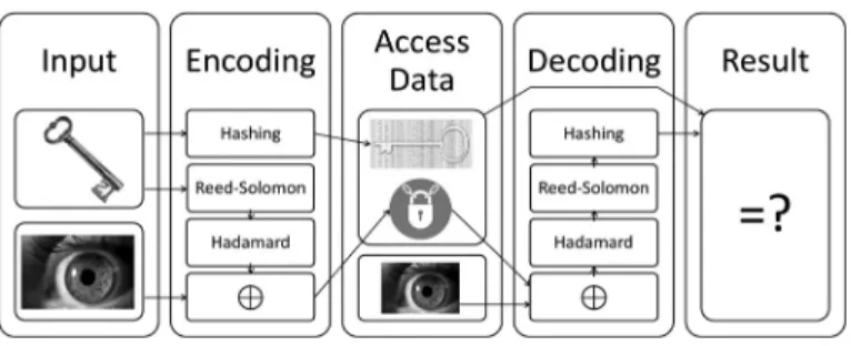
The Cambridge biometric cryptosystem is an al-gorithm that confirms user authenticity through the use of an iris template. Each user in the system is enrolled by providing a 256-byte iris template and receiving a randomly generated 140-bit key. These two inputs are used to gen-erate two variables that are stored on a physical token that the user receives. The first of the gen-erated variables is a hash of the original 140-bit key. This hash function is a mapping function used to obscure the original 140-bit key. The second variable, called a locked template, is the result of performing an exclusive-or(XOR) function between the enrollment template and the result of putting the randomly generated key through Reed-Solomon and Hadamard encod-ing sequentially[6, 7]. When a user attempts to gain access to the system, the user provides an iris sample and the physical token. The locked template is XORed with the user’s sample tem-plate, producing the encoded key with errors in-troduced by the differences between the enroll-ment template and the sample template. This result is then put through Hadamard decoding, followed by Reed-Solomon decoding. If the person attempting to access the system is a valid user with the correct token, the result of the de-coding will be the original key. If someone is trying to access the system using someone else’s token, the result will be different. The decoded key is hashed after calculation using the same hash method as in the enrollment process, and then compared to the hashed result stored on the token. If they are the same, the user is deemed valid and granted access. If the results are dif-ferent, then the user is treated as an imposter and is not given access to the system. A block diagram of this cryptosystem is shown in Fig-ure 1.
of an iris template. Burst errors are often caused by eyelashes blocking views of the iris or other devices that cause significant error in the pic-ture. Reed-Solomon code handles these errors by dividing the input into several blocks. The blocks are interpreted as coefficients to a poly-nomial using the domain of a Galois field. Ad-ditional parity blocks are added to create a re-sulting polynomial that is evenly divisible by the defining polynomial of the Galois field. During the decoding process, the division is performed on the input blocks, and the remainder is used to locate blocks that are in error. These error blocks are then entirely recalculated based on the results. This means the number of errors in a particular block does not matter, only the number of blocks that contain errors. For the Cambridge biometric cryptosystem, the 140-bit input is divided into 20 blocks of 7 bits, and 12 parity blocks are added to create a result of 32 blocks of 7 bits. This allows the system to cor-rect up to 6 block errors for any given encoding and decoding process.
Hadamard coding is used by the Cambridge bio-metric cryptosystem to handle random errors in the iris template. These are small errors that may be caused by transmission errors, or may be related to minor changes in the image of the iris taken. Hadamard coding is based on the concept of the Hadamard matrix, a matrix con-taining positive and negative values with a mag-nitude of one, where the values are arranged in a particular order. The initial Hadamard matrix, of order one, is shown in Equation 1.
H1=
+ +
+ −
(1)
Subsequent Hadamard matrices are computed as shown in Equation 2.
Hk=
Hk−1 Hk−1
Hk−1 −Hk−1
(2)
A Hadamard code uses a matrix that differs from a Hadamard matrix in two ways. The first is that the additive inverse of the Hadamard matrix is stacked below the original matrix as shown in Equation 3. The second is that all negative ones in the Hadamard matrix are replaced by zeros.
Hc=
H
−H
(3)
Hadamard encoding interprets its input as a se-ries of blocks. Each block is treated as a row index. The output result of the block is the entirety of the row corresponding to that index. During the decoding process, each block is com-pared to every row of the Hadamard matrix, and the row index corresponding to the row with the least bit differences from the input block is the output. This allows the system to return the correct output if the number of bit errors is less than half the minimum distance between rows of the matrix. For the Cambridge biomet-ric cryptosystem, the input consists of 32 7-bit blocks. A block size of seven means that there are 128 rows in the matrix. Since the matrix used is constructed from two square matrices stacked on top of each other, each row consists of 64 bits. Thus, the resulting output is 32 64-bit blocks. This choice allows each block to contain up to 15-bit errors before becoming a burst error.
The Cambridge biometric cryptosystem appears to successfully fulfill the requirements of a strong and safe biometric cryptosystem. Ac-cording to the tests performed by Anderson et al., the system performed with a 99.5 % correct
match rate [6]. The algorithm answers secu-rity concerns by storing only modified versions of the key and iris template, protecting these from being accessed by intruders. In the event that a user’s access data is compromised, a new random key can be generated for that user, re-setting the system without loss of functional-ity. This combination of accuracy and security makes the Cambridge biometric cryptosystem a strong choice for our subsequent software im-plementation and hardware acceleration.
4. Hardware Acceleration
Since the development of the computer, people have been trying to make computation faster. This was initially achieved through increasing the speed of Central Processing Units (CPUs)
that handle a single stream of instructions. But recently, CPUs have started to reach a level where their performance cannot be increased without generating more heat than can be dissi-pated in a reasonable amount of time and space
[8]. This has caused the growth of research into new areas of computational acceleration. New methods of computation focus on two as-pects: running multiple instruction sequences
(known as “threads”) simultaneously, and de-creasing the execution time of certain instruc-tions. These goals are usually accomplished through the use of multiple CPU cores running in parallel, a graphical processing unit(GPU), or custom hardware. Using multiple CPU cores allows the execution of multiple threads simul-taneously on one CPU. This is effective in sce-narios where programs have many sequences of instructions that are not dependent on one another. However, the fact that the hardware in the CPU is not being modified, just made more plentiful, means that instructions are not executed any faster. Programs without oppor-tunity for parallel computation do not benefit from multi-core hardware architecture. Simi-larly, making use of a GPU allows significantly increased parallelism by performing multiple calculations simultaneously. In addition, GPUs are optimized to perform certain types of calcu-lations commonly used in graphics processing, allowing faster execution time for these instruc-tions. The disadvantage of GPUs is that they are optimized for particular types of calculations,
reducing the benefits they provide for computa-tion of a more general type. Alternatively, cus-tom hardware allows particular hardware units to be defined to handle certain computations
[9]. Systems can be tailored to optimize for the most common form of computation in the target application. For custom hardware, the amount of parallelism in computation is defined by the amount of hardware space allocated by the designer for additional hardware for each particular functionality. The disadvantage of this method is that custom hardware must be designed specifically for the system it is in-tended for, as opposed to off-the-shelf CPUs or GPUs. This takes significant amount of de-sign time, and also requires the use of customiz-able hardware resources, whether a Field Pro-grammable Gate Array (FPGA)or a Complex Programmable Logic Device (CPLD). These hardware devices consist of a variety of hard-ware resources that can be configured in varying manners to produce the custom hardware. Hardware acceleration also changes energy ef-ficiency in addition to processing speed. A system using hardware acceleration has more hardware to power than the same system with-out hardware acceleration, causing an increase in the power consumed. However, the energy usage also depends on the time, which typically decreases during the process of hardware accel-eration[10]. Depending on the rates of change in time and power consumption, it is possible to improve the total energy usage with hardware acceleration.
This project makes use of an FPGA for the im-plementation and testing of the biometric cryp-tosystem, in order to be able to tailor the system as exactly as possible for the maximum potential benefit. An FPGA was chosen as the method of customizable hardware due to its increasing use in commercial product releases. An FPGA is an integrated circuit consisting of logic blocks and Random Access Memory (RAM) blocks designed to be configured by a customer or a designer after manufacturing. The hardware used for the project is a Xilinx Zedboard [11], a system-on-a-chip(SoC)that incorporates the functionality of an ARMdual-core CortexTM
FPGA portion of the chip for hardware accel-eration of various functions. This makes the platform an ideal setup for testing custom hard-ware acceleration.
In addition to the hardware package, the Xil-inx Zedboard also comes with software to pro-gram the system. Xilinx Software Development Kit (SDK) and Vivado software packages are used for programming the software and hard-ware components, respectively[12]. The Xilinx SDK software version 2013.4 used in this work allows a user to create, download, and run C code on the Zedboard, while the Xilinx Vivado Design Suite version 2013.4 used in this work allows the user to create custom hardware se-tups. These setups can be converted into binary configuration files used by SDK to setup the Zedboard. This setup allows the algorithm to be run both with and without hardware accel-eration. Different software functions in the al-gorithm are implemented through the hardware acceleration process and the results in terms of performance and efficiency are compared.
5. Methodology
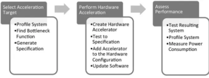
The process used to generate a hardware-accele-rated version of the Cambridge biometric cryp-tosystem consisted of several steps. The first component of the project was identifying the target function for acceleration. Once this was completed, a hardware accelerator was designed for the target function. Upon completion of the hardware accelerator, the software was modi-fied to make use of the new component. The resulting system was then tested and analyzed to determine its overall effectiveness. The process flow diagram for this methodology is shown below in Figure 2.
The system setup for this project involved a Zedboard, a computer with Xilinx SDK and
Figure 2.Methodology flowchart.
Xilinx Vivado software and at least two avail-able USB ports, and two USB-microUSB ca-bles. The Zedboard was plugged in and set to cascaded JTAG mode by setting bits MIO[6 : 2]
to ground. One USB-microUSB cable was con-nected between the UART port of the board
(J14)and the computer, and the other was con-nected between the JTAG (J17) port and the computer. The board was then powered on. In Xilinx SDK, the port used to program the FPGA was set to the port that was connected to the JTAG pin.
This research made use of a C implementation of the Cambridge biometric Cryptosystem de-veloped by the authors for a past research project
[13]. In order to find a target function for hard-ware acceleration, the system was profiled using the profiling option built into the SDK software. This functionality uses a timer to generate hard-ware interrupts periodically. At each hardhard-ware interrupt, the system stores its current location in the program flow. The number of data points can be used to determine total system runtime while the locations of the data points can be used to determine the amount of time spent on each function, and the number of times each function was called during execution. The snoop control unit(SCU)timer on the Zedboard was used to generate the interrupts.
The profiling results provided a breakdown of the total time required for computations in the system, and how that time was spent. Using this data, the function that required the most computation time was selected as the target for hardware acceleration.
Extensible Interface (AXI) between the pro-grammable logic(PL)and the PS. This involved converting between data registers and input or output signals and converting control registers to individual control signals for the computa-tional component. Each component was indi-vidually tested to ensure that it met specifica-tions prior to combining the pieces to generate the finished hardware accelerator. This acceler-ator was then added to the hardware configura-tion.
Once the hardware setup was updated with the new accelerator, the next step was to edit the software project to use the hardware acceler-ator instead of the original software function. This was done using the SDK software. A
C function was written with the same input and output arguments as the original function. Rather than performing the computation, this function would send the appropriate data to the memory-mapped registers used for input and control. The function would then wait for a signal from the hardware accelerator indicating that the computation was finished. Upon re-ception of this signal, the function would read the output register and return the appropriate re-sults. Each instance of the original computation function in the project was then replaced by a call to the new function, completing the soft-ware changes. After each change, the softsoft-ware was tested to ensure that its functionality was unaffected.
Performance evaluation was the final phase of the project. After each hardware accelerator was added to the system, the resulting system was profiled as described above. This provided data about the runtimes of the overall system and the specific function accelerated. This data was used to calculate total runtimes and system speedups for the entire system and the target functions. Additionally, the system power us-age report generated by Vivado was used to ob-tain the power usage of each system. Multiply-ing the power usage by the total time per com-putation provided an estimation of the amount of energy consumed by that calculation. These time and energy statistics allow us to compare the different systems and evaluate the effective-ness of the acceleration process.
6. Results and Discussion
6.1. Initial Software Profiling
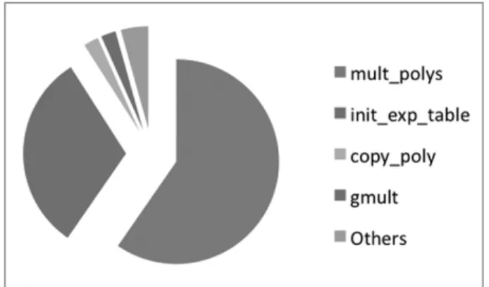
In order to select a target function for hardware acceleration, the initial software implementa-tion of the Cambridge biometric cryptosystem was profiled as described above. Due to the separation of the enrollment and verification processes, three distinct runtime profiles were generated: one for each process run individ-ually, and one for enrollment and verification run in sequence. These runtime profiles are shown in Figure 3, Figure 4, and Figure 5, re-spectively. For this data, time spent on pro-filing functions has been removed in order to focus on the algorithm runtime. Functions that took less than 50 microseconds were combined into the “others” section to simplify the infor-mation. According to the verification and se-quential profiles, the functions with the most computational cost and thus the greatest poten-tial for hardware acceleration are the mult polys function, the hadamard decode function, and
Figure 3.Profiling results for the initial software implementation of enrollment.
Figure 5.Profiling results for the initial software implementation of enrollment followed by verification.
the init exp table function. The profile for en-rollment does not have the same cost for the hadamard decode function since this function is only used during verification. Thus hardware acceleration began on the mult polys function.
6.2. Hardware Accelerator Setup
The hardware acceleration process involves sev-eral different phases, as described in Section V. The results of each of these phases will be dis-cussed individually below.
The first step in the acceleration process was creating an input/output specification for the mult polys function. This function takes two input arrays and returns one output array. In the general case, the input arrays can be of any size, and the size of the output array is equal to the sum of the sizes of the two input arrays. For this particular program, both input arrays have the size equal to twice the number of par-ity bytes used in the Reed-Solomon Codes: 24 bytes. The mapping from input to output is very similar to that of regular polynomial mul-tiplication. Each array element is treated as a coefficient to a polynomial where the index of the array corresponds to the power of the term. When doing regular polynomial multiplication, each term in the first array would be multiplied with each term in the second array. The result from each multiplication is added to the output term with power (index) equal to the sum of the powers of the two inputs. In the mult polys function, this process is changed slightly. Mul-tiplication across a Galois Field is used rather than multiplication for combining terms. The addition used for combining the output terms is
replaced with the XOR operation. This process, combined with the knowledge of the input and output sizes, completes the specification of the mult polys function.
The hardware accelerator was designed to per-form the same computations as the software function, but in a manner that allowed mul-tiple computations to be executed in parallel. The first step was designing a component that would perform multiplication across a Galois field. In the software version of the system, Galois multiplication was performed by taking the log of both inputs across a Galois field, and then taking the Galois exponential of the sum of the results. This method works for all non-zero inputs. Any non-zero inputs were handled by a check prior to computation, and simply re-turning zero if a zero input existed. The Galois multiplication hardware was designed using the same algorithm. Memory blocks were created for the Galois logarithm and Galois exponen-tiation functions. Once these memory blocks were completed, combining them to create Ga-lois multiplication became a relatively simple task.
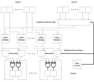
After the Galois multiplication component was designed and tested, the mult polys accelerator could be constructed. The component design diagram for this component can be found in Fig-ure 6. This hardware component makes use of a number of Galois multiplication components equal to the size of the first input array: 24 in this case. For each component, the correspond-ing term of the first input array is the first factor.
The second factor is time dependent, but com-ponent independent. That is, the second factor changes over time, but is the same for any com-ponent at the same time. At the beginning of the computation, the second factor is the first term of the second array. Each computation cycle, the next lowest index term is used as the second factor for the components. These computations combine to create every combination of terms between the two input arrays.
The output of the computation is stored in a larger output vector. When computation starts, this vector is initialized to all 0’s. Upon com-pletion of a computation, the result of the multi-plication component is XORed with the appro-priate output term, and then stored as the new output term. Because the XOR operation is commutative and associative, the order of these operations does not affect the computation. The appropriate output term is found by adding the index of the second array used as a factor to the multiplication component number. This results in the lower order terms being processed before the higher order terms, with the same number of computations taking place during each compu-tation cycle. After all compucompu-tation cycles have been completed, the output vector is complete, and can be sent back to the processor.
Creating the AXI Interface to the processor in-volved developing input and output buffers, and a control buffer that the processor could use to control the system by setting flags. The con-trol flags are simple: one bit for the processor to tell the accelerator to begin computation and one bit for the accelerator to tell the processor when computation has finished. For this com-ponent, the input and output buffers were the same. Upon receiving a start signal, the ac-celerator reads the input buffer into its internal memory, then clears the control buffer. When the computation completes, the system over-writes the result to the input/output buffer and writes a 1 to the completion bit and a 0 to the start bit. This interface completes the input and output requirements for this accelerator.
The hardware components were tested using the simulation software in Vivado. The inputs to the system were forced to particular values, and the output signals were observed. This allowed the designers to validate the correctness of the system.
After the simulation phase, adding the hardware accelerator to the hardware system took place in the Vivado environment. An instance of the accelerator was created, and connected to the processor using an AXI interface. This results in the processor treating the accelerator as a memory-mapped peripheral. This change also required setting one of the PL clocks to control the accelerator. For this research, a clock fre-quency of 200 MHz was chosen since it was the highest frequency supported. This new hard-ware configuration was then imported into SDK in order to update the software.
Updating the software involved replacing calls to the mult polys function with calls to the hardware accelerator. A replacement function with the same signature was created that could be called by other sections of the code that re-quired this computation. This function, called mult polys HW, made use of the memory-map-ped accelerator. Using the memory locations specified in the configuration files, it would load the inputs into the appropriate registers, then write a 1 to the start flag. The function would then periodically check the completion flag. Upon the flag becoming a 1, the function would read the data from the registers and return them to its caller. Once this function was completed and tested, calls to mult polys in the project were replaced with calls to mult polys HW. This completed the acceleration cycle.
6.3. Hardware Accelerator Profiling
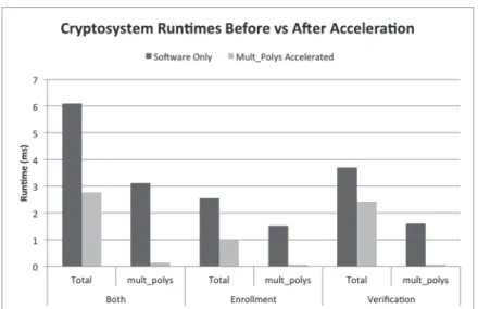
Figure 7. Cryptosystem runtimes before and after hardware acceleration.
individual processes based on their relative run-time.
Function
Runtime before Acceleration (ms)
Runtime after Acceleration (ms)
Speedup
Enrollment 2.55 0.97 2.63
Verification 3.7 2.43 1.52
Both 6.09 2.77 2.20
Table 1.Hardware acceleration speedups.
The hardware acceleration also affected the to-tal energy usage of the system. The additional hardware component caused the power usage to change from 1.477 W to 1.704 W, represent-ing a 15.4 % increase. However, the amount of energy used for any given computation was reduced due to the improved runtime. Table 2 shows the energy consumption of the result-ing systems. Since the power usage is constant
Function
Energy before Acceleration (mJ)
Energy after Acceleration (mJ)
Percentage of
Reduction
Enrollment 3.77 1.65 56.1
Verification 5.46 4.14 24.2
Both 8.99 4.72 47.5
Table 2.System energy consumption.
between different computation sets, the energy usage follows the same patterns as the runtime data.
These results show that hardware acceleration is an effective choice for improving the overall ef-ficiency of biometric cryptosystems. The hard-ware acceleration caused significant decreases in the runtime of the original system. These runtime decreases help outweigh the additional power that they require, resulting in overall en-ergy cost reductions per computation.
6.4. Comparison with Multi-Core Acceleration
Comparing the results of custom hardware ac-celeration methods to alternative methods al-lows researchers to analyze the similarities and differences of methods and their relative lev-els of effectiveness. One such comparison can be drawn between this work and the many-core acceleration methods applied to the Cam-bridge biometric cryptosystem [14], in which case the authors used the 48-core Intel Single-Chip Cloud Computer(SCC)platform.
function is of parallel computation type, which is suitable for being distributed over many cores for parallel processing. The acceleration of hadamard decode resulted in a speedup of up to 1.18X [14]. The limited effectiveness of this approach can be explained with a cou-ple of reasons. The first reason is that the hadamard decode function takes a lower per-centage of the computation runtime than that of the mult polys function, as shown in Figures 3-4. Another reason is that in the many-core implementation, the MPI-like (message pass-ing interface) programming model contributed significant communication overhead.
This shows that custom hardware acceleration can have greater potential impact on system run-times than many-core acceleration for this ap-plication. However, due to the fact that many-core systems are more prevalent and versatile than custom hardware systems, which must be designed for a particular operation, a hybrid ap-proach would provide the benefits from both approaches.
7. Conclusions
Biometric cryptosystems represent a future di-rection that provides user security without the drawbacks of traditional password-based ap-proaches. By combining biometrics with cryp-tography, biometric cryptosystems allow accu-rate matching of biometrics in an encrypted and secure domain. This is an important step to-wards creating a network where data can be protected efficiently and securely. Henceforth, improving the efficiency of biometric cryptog-raphy would greatly enhance its potential to be readily deployed towards modern network se-curity.
In this work, a concrete software implementa-tion of the biometric cryptosystem developed by Anderson, Daugman, and Hao at the University of Cambridge has been optimized using hard-ware acceleration. The result is a system that can perform user enrollment in 0.97 ms and user verification in 2.43 ms on a Xilinx Zedboard System-on-a-Chip (SoC) platform, represent-ing a 2.63X and 1.52X speedup comparrepresent-ing with the software counterpart. This system requires only 1.704 W of power, resulting in energy con-sumption of 1.65 and 4.14 mJ for enrollment
and verification, respectively. This represents a 56.1 % and 24.2 % reduction comparing with the software counterpart.
This work also compares the custom hardware acceleration with a many-core acceleration im-plementation of the same system. This compar-ison illustrates the greater acceleration poten-tial provided by custom hardware acceleration compared to parallel computing on many-core platform, and the corresponding increase in de-signer overhead. Understanding these tradeoffs allows system designers to select the best hard-ware system for their application.
In addition to providing a concrete implemen-tation of a biometric cryptosystem, this project provides a process that can be used as a guide-line for future applications of hardware accel-eration to biometric cryptosystems for network security. Making use of this methodology will allow for the development of systems that take significantly less runtime and less energy per computation, significantly increasing their use-ful potential.
Acknowledgment
The Zedboard SoC platform used for FPGA im-plementation is provided through Xilinx Uni-versity Program. The Intel Single Chip Cloud Computer Platform is provided by Intel Labs. This work is supported by the National Science Foundation under Grant Numbers IIP-1332046, IIP-1068055 and ECCS-1301953. Any opin-ions, findings, and conclusions or recommen-dations expressed in this material are those of the authors and do not necessarily reflect the views of the National Science Foundation.
References
[1] T. HEY, S. TANSLEY, K. TOLLE, The fourth paradigm,
data-intensive scientific discovery. Microsoft Re-search, Redmond, WA.
[2] A. JAIN, A. ROSS, U. ULUDAG, Biometric template
security: challenges and solutions.European Signal Processing Conference,(2005).
[3] U. ULUDAG, S. PANKANTI, S. PRABHAKAR,
A.K.JAIN, Biometric cryptosystems: issues and
challenges.Proceedings of the IEEE,92(6),(2004)
[4] A. ROSS, A. OTHMAN, Visual cryptography for
bio-metric privacy.IEEE Transactions on Information Forensics and Security,6(1),(2011)pp. 70–81.
[5] C. RATHGEB, A. UHL, A survey on biometric
cryp-tosystems and cancelable biometrics. Journal on Information Security,2011,(2011)pp. 3.
[6] R. ANDERSON, J. DAUGMAN, F. HAO, Combining
cryptography with biometrics effectively. Technical Report 640, University of Cambridge, 2005.
[7] C. CLARK, Reed-Solomon error correction. British
Broadcasting Company Research and Development White Paper, WHP 031, July 2012.
[8] C. LIU, R. DUARTE, O. GRANADOS, J. TANG, S. LIU, J. ANDRIAN, Critical path based hardware accel-eration for cryptosystems. International Journal of Advancements in Computing Technology, 4(1),
(2012)pp. 438–452.
[9] D. LAU J. BLACKBURN C. JENKINS, Using
c-to-hardware acceleration in FPGAs for waveform base-band processing.Software Defined Radio Technical Conf. Product Exposition,(2006).
[10] C. LIU, O. GRANADOS, R. DUARTE, J. ANDRIAN,
Energy efficient architecture using hardware ac-celeration for software defined radio components.
Journal of Information Processing Systems, 8(1),
(2012)pp. 133–144.
[11] GETTING STARTED WITH ZEDBOARD. Version 7,
AVnet Electronics Marketing.
[12] ZYNQ ALL PROGRAMMABLESOCLINUX-FREERTOS AMP GUIDE. Version 2013.10, Xilinx, November 25, 2013.
[13] C. MCGUFFEY, C. LIU, S. SCHUCKERS,
Implemen-tation and optimization of a biometric cryptosystem using iris recognition. Biometric and Surveillance Technology for Human and Activity Identification XII, SPIE DSS 2015, Baltimore, Maryland, USA, April 20-24, 2015.
[14] C. MCGUFFEY, C. LIU, Multi-core Approach
To-wards Efficient Biometric Cryptosystems.The 2015 International Workshop on Embedded Multicore Systems (ICPP–EMS 2015), in conjunction with ICPP 2015, Beijing, China, September 1-4, 2015.
[15] P. REID,Biometrics and Network Security. Prentice
Hall PTR, Upper Saddle River, NJ, USA, 2003.
Received:August, 2015
Revised:October, 2015
Accepted:October, 2015
Contact addresses:
Charles McGuffey Clarkson University 8 Clarkson Avenue Potsdam NY 13699 USA e-mail:[email protected]
Chen Liu Clarkson University 8 Clarkson Avenue Potsdam NY 13699 USA e-mail:[email protected]
Stephanie Schuckers Clarkson University 8 Clarkson Avenue Potsdam NY 13699 USA e-mail:[email protected]
MR. CHARLESMCGUFFEYobtained his B.S. Degree with Honors in Computer Engineering and Computer Science in 2015 from Clarkson University, Potsdam, New York, USA. He is currently a Computer Science Ph.D. candidate at Carnegie Mellon University. His research interests include hardware acceleration, many-core computing and al-gorithm design.
DR. CHENLIUreceived the B.E. Degree in Electronics and
Informa-tion Engineering from the University of Science and Technology of China in 2000, the M.S. Degree in Electrical Engineering from the University of California, Riverside in 2002, and the Ph.D. Degree in Electrical and Computer Engineering from the University of California, Irvine in 2008, respectively. Currently he is an assistant professor in the Department of Electrical and Computer Engineering at Clarkson University, Potsdam, New York, USA. His research interests are in the areas of multi-core multi-threading architecture, hardware acceleration for scientific computing and the interaction between system software and micro-architecture. He is a member of IEEE, ACM, and ASEE.