T
HE
A
NALYSIS OF
L
ATERAL
S
TABILITY OF
T
AILLESS
C
AMAR
-3
W
ITH
W
INGLETS
Koo Hwai Yeng Koo, Dr. –Ing. Mohd Nazri bin Mohd Nasir, Prof. Ir. Dr. Shuhaimi bin Mansor*
School of Mechanical Engineering, Faculty of Engineering
Universiti Teknologi Malaysia
81310 UTM Johor Bahru, Johor, Malaysia
Article history Received 27 November 2019 Received in revised form
24 December 2019 Accepted 29 December 2019
Published Online 29 December 2019
*Corresponding author [email protected]
G
RAPHICALA
BSTRACTK
EYWORDSTailless UAV; dynamic wind tunnel test; aerodynamic stability derivatives; lateral stability; winglets
A
BSTRACT1.0 INTRODUCTION
The use of Unmanned Aerial Vehicles (UAVs) is growing exponentially across many civil and military applications due to their versality, ease of deployment, high-mobility and ability to hover [1]. Since demands for the use of UAV systems are increasing, enhancement of stability, performance and efficiency of the UAV is a vital and continuous research topic, in order to increase their safety and reliability during flight.
CAMAR is a medium size autonomous unmanned aircraft designed by UTM researchers to support the advancement of local UAV industries. The main goal of CAMAR is to be a high endurance autonomous unmanned aerial system, tailored for aerial observation and flight research facility. In order to achieve the missions, the CAMAR is required to have high endurance capability.
Endurance depends mainly on aerodynamic design of the UAV. Conceptually, the main aerodynamic advantage of a tailless aircraft is its lower wetted area to volume ratio and lower interference drag, as compared to aircraft with conventional configuration. By removing the tail of CAMAR, weight and drag on CAMAR will be reduced and may result in longer endurance time [2] [3].
Nevertheless, a tailless configuration presents a unique challenge from the perspective of stability and control, when the main source of yaw control is lost [4]. In addition, Okonkwo and Smith [5] explained that a tailless aircraft has low yaw control authority due to its shorter moment arm, compared to aircrafts with conventional tail configuration. In brief, the downside of a tailless aircraft configuration is the reduction in directional stability and manoeuvrability due to the unavailability of vertical tail and traditional rudder for yaw control [6] [7]. As a result, a tailless CAMAR might lose its stability, especially in lateral direction. Hence, there is a compromisation between the performance and stability.
According to the research done by the Flight Control Division of Soviet Union Department of Defence, it was stated by Bowlus, et al. [8] that one of the most effective devices in generating yaw control power for a tailless fighter was an all moving wingtip. This view is shared by Liebeck [9], who proposed in using winglet rudders as primary directional stability and control surface. Baig, et al. [10] also suggested that winglets mounted at the wingtips can be used in place of the vertical tail to control yawing motion and reduce the strength of wingtip vortices. Therefore, for tailless aircraft that has swept-back wing (i.e. CAMAR-3), the winglets should be placed at the wingtip extremities to take advantage of the longest moment arm available, to enhance yaw stability.
Aerodynamic derivative determination is essential in analysing aircraft stability. Nonetheless, as pointed out by Musa [11], a new design of aircraft configuration will initially suffer the lack of aerodynamic derivatives. Most of the aircraft modelling were rely on steady-state measurements either through semi-empirical method or traditional static wind tunnel tests to attain the aircraft responses [4] [12] [13]. In preliminary design phase, it was suggested by Ciliberti, et al. [13] to assess the aircraft stability with semi-empirical method by estimating the aerodynamic stability derivatives. To evaluate aircraft lateral stability more accurately for unconventional aircraft configurations especially during transient conditions, a dynamic test rig based on pure yawing motion is required to measure the lateral stability derivatives of 𝐶𝑛𝛽 and 𝐶𝑛𝑟. In accordance to the method
2.0 MODEL AND TEST SET-UP
2.1 Preliminary Design of Winglets
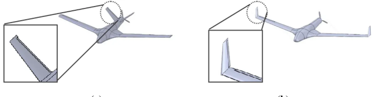
With the same aspect ratio and taper ratio of the ruddervator of CAMAR-3 (Figure 1(a)), it was reconfigured to the wingtip of the tailless CAMAR (Figure 1(b)). In order to fit the winglet to the wingtip of CAMAR-3, without changing its major configuration including the wing dimension, the root chord of the winglet is as the same as the wingtip chord length, 0.16 m. The parameters of ruddervator and winglet are tabulated in Table 1.
(a) (b)
Figure 1: (a) Ruddervator of CAMAR-3 (b) Winglet of tailless CAMAR-3
Table 1: Parameters of ruddervator and winglet for CAMAR
Parameters ruddervator Values for
Ruddervator
Values for Winglets Root chord 0.200 𝑚 0.160 𝑚
Tip chord 0.110 𝑚 0.088 𝑚
Mean chord length 0.155 𝑚 0.124 𝑚
Span 0.310 𝑚 0.248 𝑚
Area 0.04805 𝑚2 0.03075 𝑚2
Taper Ratio 0.55 0.55
Aspect Ratio 2 2
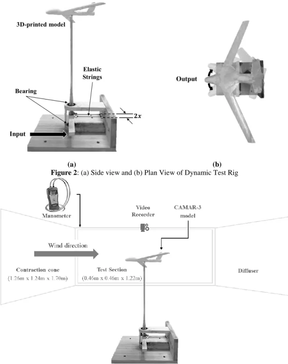
2.2 Dynamic Wind Tunnel Test
For dynamic wind-tunnel test, the clean configuration model of CAMARs are 3D-printed in scale 1:8 and a dynamic test rig is built as shown in Figure 2. The dynamic test rig is developed in such a way that the model is constrained for pure yawing motion. When the model is given an initial displacement in yaw angle 𝛽𝑜 and released, the motion will be
recorded and analysed.
(a) (b)
Figure 2: (a) Side view and (b) Plan View of Dynamic Test Rig
Figure 3: Experimental setup for dynamic wind tunnel test
3.0 ESTIMATION OF AERODYNAMIC DERIVATIVES
For semi-empirical method, the aerodynamic lateral stability derivatives 𝐶𝑛𝑟 and 𝐶𝑛𝛽, are
estimated in accordance to Roskam [15]. For the purposes of this study, the aerodynamic loads are considered to act as stiffness and damping to the model motion. Generally, the aerodynamic stability derivatives are given by Nelson [16]:
𝐶𝑛𝛽 =𝑁𝛽𝐼𝑧𝑧
𝐶𝑛𝑟 =
2𝑁𝑟𝐼𝑧𝑧𝑢𝑜
𝑄𝑆𝑏2 (2)
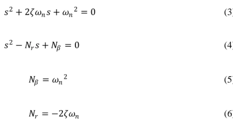
By comparing the standard second order characteristic equation (Eq.3) and the characteristic equation of pure yawing motion (Eq.4), the aerodynamic stiffness (Eq.5) and aerodynamic damping (Eq. 6) of oscillation can be determined.
𝑠2+ 2𝜁𝜔
𝑛𝑠 + 𝜔𝑛2= 0 (3)
𝑠2− 𝑁
𝑟𝑠 + 𝑁𝛽 = 0 (4)
𝑁𝛽 = 𝜔𝑛2 (5)
𝑁𝑟 = −2𝜁𝜔𝑛 (6)
The damping ratio, 𝜁 and natural frequency, 𝜔𝑛 can be obtained from time response plot
(as shown in Figure 4), along with the following equations:
𝜁 = 𝑐𝑜𝑠 𝑡𝑎𝑛−1 𝜔𝑑
𝜉𝜔𝑛 (7)
𝜔𝑛 = 𝜔𝑑
1−𝜉2 (8)
In accordance to Mansor and Passmore [14], the aerodynamic derivatives can be measured by comparing the wind-on and wind-off oscillatory frequency and damping ratio from time response resulted by dynamic wind tunnel test. Hence, the aerodynamic derivatives from wind tunnel test can be obtained from:
𝑁𝛽 = 𝜔𝑛2
𝑤𝑖𝑛𝑑 −𝑜𝑛 − 𝜔𝑛2 𝑤𝑖𝑛𝑑 −𝑜𝑓𝑓 (9)
𝑁𝑟 = −2𝜁𝜔𝑛 𝑤𝑖𝑛𝑑 −𝑜𝑛 − −2𝜁𝜔𝑛 𝑤𝑖𝑛𝑑 −𝑜𝑓𝑓 (10)
4.0 RESULTS AND DISCUSSION
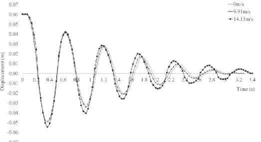
The dynamic test rig must have low damping ratio and stiffness in order to detect the relatively small aerodynamic stiffness and damping. It is shown in Figure 5 that the test rig has sufficient sensitivity to detect the aerodynamic behaviour of the model. As airspeed increases, the aerodynamic effect becoming more obvious to show the difference between wind-on and wind-off conditions. It is indicated that greater airspeed results in shorter period of oscillation, hence increase in oscillatory frequency and greater aerodynamic stiffness, 𝑁𝛽 . For aerodynamic damping, 𝑁𝑟 at 9.91 m/s, no clear
aerodynamic damping exists; but surprisingly the aerodynamic damping becoming less at 14.15m/s.
Figure 5: Time response graph of dynamic wind tunnel test at 0 m/s, 9.91m/s and 14.15 m/s.
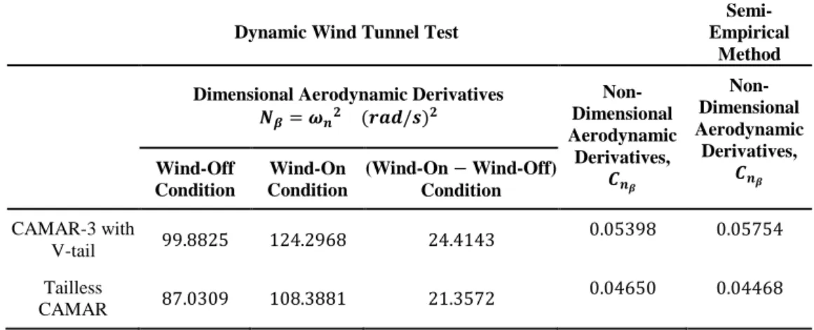
Results have been obtained from time response data of dynamic wind-tunnel test at airspeed 9.91 m/s, which are similar to values estimated from semi-empirical method (as listed in Table 2 and Table 3). From Table 2, experimental result shows that tailless-winglets CAMAR has a 13.86% reduction in 𝐶𝑛𝛽, compared to CAMAR-3 with V-tail;
Table 2: Computed result of 𝐶𝑛𝛽 from wind tunnel test and semi-empirical method at 9.91 m/s.
Dynamic Wind Tunnel Test
Semi-Empirical
Method
Dimensional Aerodynamic Derivatives 𝑵𝜷= 𝝎𝒏𝟐 (𝒓𝒂𝒅/𝒔)𝟐
Non-Dimensional Aerodynamic
Derivatives, 𝑪𝒏𝜷
Non-Dimensional Aerodynamic
Derivatives, 𝑪𝒏𝜷
Wind-Off Condition
Wind-On Condition
(Wind-On − Wind-Off) Condition
CAMAR-3 with
V-tail 99.8825 124.2968 24.4143
0.05398 0.05754
Tailless
CAMAR 87.0309 108.3881 21.3572
0.04650 0.04468
Table 3: Computed result of 𝐶𝑛𝑟 from wind tunnel test and semi-empirical method at 9.91 m/s.
Dynamic Wind Tunnel Test
Semi-Empirical
Method
Dimensional Aerodynamic Derivatives 𝑵𝒓= −𝟐𝜻𝝎𝒏 𝒓𝒂𝒅/𝒔
Non-Dimensional Aerodynamic
Derivatives, 𝑪𝒏𝒓
Non-Dimensional Aerodynamic
Derivatives, 𝑪𝒏𝒓
Wind-Off Condition
Wind-On Condition
(Wind-On − Wind-Off) Condition
CAMAR-3 with
V-tail −1.2893 −1.5840 −0.2947 −0.04305 −0.03670
Tailless
CAMAR −1.6005 −1.8832 −0.2827 −0.04066 −0.02047
5.0 CONCLUSION
The result of both dynamic wind-tunnel test and semi-empirical method has shown degradation in lateral stability when the tail is removed and winglets are used as directional controllers. However, the reduction in effectiveness is relatively small. Thus, the idea of tail removal and using winglets to act as yaw control surfaces is considered feasible.
REFERENCES
[1] S. Hayat, E. Yanmaz, and R. Muzaffar, "Survey on Unmanned Aerial Vehicle Networks for Civil Applications: A Communications Viewpoint," IEEE Communications Surveys and Tutorials, vol. 18, no. 4, pp. 2624-2661, 2016.
[2] H. Karakas, E. Koyuncu, and G. Inalhan, "ITU Tailless UAV Design," Journal of Intelligent & Robotic Systems, vol. 69, no. 1-4, pp. 131-146, 2013.
[3] J. Weierman and J. Jacob, "Winglet Design and Optimization for UAVs," in 28th AIAA Applied Aerodynamics Conference, 2010, p. 4224.
[5] P. Okonkwo and H. Smith, "Review of Revolving Trends in Blended-Wing-Body Aircraft Design," Progress in Aerospace Sciences, vol. 82, pp. 1-23, 2016.
[6] G. Larkin and G. Coates, "A Design Analysis of Vertical Stabilisers for Blended-Wing-Body Aircraft," Aerospace science and technology, vol. 64, pp. 237-252, 2017.
[7] X. Qu, W. Zhang, J. Shi, and Y. Lyu, "A Novel Yaw Control Method for Flying Wing Aircraft in Low Speed Regime," Aerospace Science and Technology, vol. 69, pp. 636-649, 2017.
[8] J. Bowlus, D. Multhopp, S. Banda, J. Bowlus, D. Multhopp, and S. Banda, "Challenges and Opportunities in Tailless Aircraft Stability and Control," in Guidance, Navigation, and Control Conference, 1997, p. 3830.
[9] R. H. Liebeck, "Design of The Blended-Wing-Body Subsonic Transport," Journal of aircraft, vol. 41, no. 1, pp. 10-25, 2004.
[10] A. Baig, T. Cheema, Z. Aslam, Y. Khan, and H. Sajid Dar, "A New Methodology for Aerodynamic Design and Analysis of a Small Scale Blended Wing Body," J Aeronaut Aerospace Eng, vol. 7, no. 206, p. 2, 2018.
[11] N. A. Musa, Importance of Transient Aerodynamic Derivatives for V-tail Aircraft Flight Dynamic Design. 2016.
[12] N. Van Nguyen, M. Tyan, J.-W. Lee, and S. Kim, "Investigations on Stability and Control Characteristics of a CS-VLA Certified Aircraft Using Wind Tunnel Test Data,"
Proceedings of the Institution of Mechanical Engineers, Part G: Journal of Aerospace Engineering, vol. 230, no. 14, pp. 2728-2743, 2016.
[13] D. Ciliberti, P. Della Vecchia, F. Nicolosi, and A. De Marco, "Aircraft Directional Stability and Vertical Tail Design: A Review of Semi-Empirical Methods," Progress in Aerospace Sciences, vol. 95, pp. 140-172, 2017.
[14] S. Mansor and M. A. Passmore, "Estimation of Bluff Body Transient Aerodynamics Using an Oscillating Model Rig," Journal of Wind Engineering and Industrial Aerodynamics, vol. 96, no. 6-7, pp. 1218-1231, 2008.
[15] J. Roskam, Airplane Design DARcorporation, 1985.