Published online June 29, 2015 (http://www.sciencepublishinggroup.com/j/ajnc) doi: 10.11648/j.sjbm.s.2016050101.14
ISSN: 2326-893X (Print); ISSN: 2326-8964 (Online)
Optimization Algorithm of Resource Allocation
IEEE802.16m for Mobile WiMAX
Bat-Enkh Oyunbileg
1, Otgonbayar Bataa
1, Tuyatsetseg Badarch
2, Baatarkhuu Tsagaan
11
Department of Information Technology, School of Information and Telecommunication, MUST, Ulaanbaatar, Mongolia
2
Department of Information Technology, Mongolian National University, Ulaanbaatar, Mongolia
Email address:
[email protected] (O. Bat-Enkh), [email protected] (B. Otgonbayar)
To cite this article:
Bat-Enkh Oyunbileg, Otgonbayar Bataa, Tuyatsetseg Badarch, Baatarkhuu Tsagaan. Optimization Algorithm of Resource Allocation IEEE802.16m for Mobile WiMAX. American Journal of Networks and Communications. Special Issue: Traffic and Performance Engineering for Networks. Vol. 5, No. 1-1, 2016, pp. 14-19. doi: 10.11648/j.sjbm.s.2016050101.14
Abstract:
Multi user resource allocation is one of the key features towards high speed wireless network based on Orthogonal Frequency Division Multiplexing Access (OFDMA). According to IEEE802.16m (Mobile WiMAX) standard resource allocation problem has to be performed on a frequency and time two-dimensional space with the Physical and logical resource units (PRU and LRU) including Distributed logical resource unit (DRU and CRU) and Contiguous logical resource unit In this paper we analysed the WiMAX frame structure in IEEE802.16m based on the Mobile WiMAX Standard. We apply novel resource allocation algorithm are used for managing two dimensional resources (time and frequency) to maximizing system capacity depending on mobile user’s data rate. This paper proposes a resource allocation algorithm for radio resource allocation in the downlink/uplink cellular networks using Orthogonal Frequency Division Multiple Access of Mobile WiMAX. Radio Resource Management (RRM) is fundamental in cellular networks. Many optimization problems involving allocation strategies of various types of resource appear in RRM. In this paper we determine the Fractional Frequency Reuse (FFR) and analyze the resources in Mobile WiMAX.Keywords:
IEEE802.16m, Mobile WiMAX, Resource Allocation, PRU, DRU, CRU and LRU, Physical Resource Units, LTE1. Introduction
The most suitable physical layer for the future deployment of Broadband Wireless Access networks is OFDMA. OFDMA has a few benefits large data rates, robustness against multi-path, flexible bandwidth allocation, and the possibility of exploiting multi-user diversity through an intelligent scheduling and resource allocation [1,3,4,9]. One of the most important advantages of OFDMA systems is included flexible resource allocation in two dimensional spaces.
The purpose of this paper is to provide resource allocation procedure and to give comparative analysis that need to be considered in developing distributed resource allocation for IEEE 802.16m. In OFDMA, the available spectrum (frequency domain) is divided into orthogonal sub-carriers, which are combined into groups, usually referred as sub-channels. Furthermore, the time domain structure is segmented into consecutive frames, each one containing
multiple OFDM symbols. A slot delimited by one sub-channel and by a given number of OFDM symbols is the smallest resource unit that a Base Station (BS) can allocate to the users. OFDMA systems can provide multi-user access assigning different sub-channels and OFDM symbols to different users. Moreover, the system can exploit multi-user diversity, allocating in each frequency and time region (two dimensions) the user with the best channel conditions. This feature makes OFDMA systems, such as Long Term Evolution (LTE) or WiMAX, more flexible than 3G solutions as High Speed Packet Access (HSPA) networks. However, these degrees of freedom present new challenges for the resource assignment and they require more sophisticated algorithms, capable of handling efficiently two-dimensional allocations.
OFDMA is considered both time and frequency domains. The OFDMA scheduler is the one of most complex problems because each MS can receive some portions of the allocation for the combination of time and frequency so that the channel capacity is efficiently utilized.
2. Downlink Physical Structure
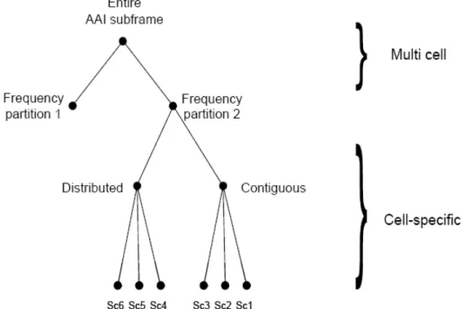
Each downlink AAI sub frame is divided into 4 or fewer frequency partitions; each partition consists of a set of physical resource units across the total number of OFDMA symbols available in the AAI sub frame. Each frequency partition can include contiguous (localized) and/or non-contiguous (distributed) physical resource units. Each
frequency partition can be used for different purposes such as fractional frequency reuse (FFR). “Fig. 1” illustrates the downlink physical structure in the example of two frequency partitions with frequency partition 2 including both contiguous and distributed resource allocations, where Sc stands for subcarrier.
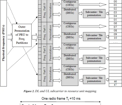
The DL/UL subcarrier to resource unit mapping process, which is used to our research, is defined as following and illustrated in the Fig. 2.
1. Outer permutation is applied to the PRUs in the units of N1 and N2 PRUs. Direct mapping of outer permutation can be supported only for CRU.
2. Distributing the reordered PRUs into frequency partitions.
Figure 1. Downlink physical structure.
3. The frequency partition is divided into localized and/or distributed groups. Sector specific permutation can be supported and direct mapping of the resources can be supported for localized resources. The sizes of the distributed/localized groups are flexibly configured per sector. 4. The localized and distributed groups are further mapped into LRUs (by direct mapping of CRU and by “Subcarrier permutation” for DRUs) as shown in the following figure [2].
Physical and logical resource unit: A physical resource unit (PRU) is the basic physical unit for resource allocation that comprises Psc consecutive subcarriers by Nsym consecutive OFDMA symbols. Psc is 18 subcarriers and Nsym is 6 OFDMA symbols for type-1 sub-frame, respectively. A logical resource unit (LRU) is the basic logical unit for distributed and localized resource al-locations.
Distributed logical resource unit: The downlink distributed logical resource unit (DLRU) contains a group of subcarriers that are spread across the distributed resource allocations within a frequency partition. The downlink DLRUs are obtained by subcarrier permuting on the data subcarriers of the
distributed resource units (DRUs). The size of the DRU equals the size of PRU, i.e., Psc subcarriers by Nsym OFDMA symbols.
Contiguous logical resource unit: The localized logical resource unit, also known as contiguous logical resource unit (CLRU) contains a group of subcarriers that are contiguous across the localized resource allocations. CLRU consists of the data subcarriers only in the contiguous resource unit (CRU) of which size equals the size of the PRU, i.e., Psc subcarriers
by Nsym OFDMA symbols. The CLRUs are obtained from
direct mapping of CRUs. Two types of CLRUs, subband LRU (SLRU) and miniband LRU (NLRU), are supported according to the two types of CRUs, sub band and miniband based CRUs, respectively.
The Advanced Air Interface supports TDD and FDD duplex modes, including H-FDD AMS operation. Unless otherwise specified, the frame structure attributes and baseband processing are common for all duplex modes. The Advanced Air Interface uses OFDMA as the multiple access schemes in the downlink and uplink.
into radio frames, each 10 ms in length. “Fig. 1” shows the frame structure for Mobile WiMAX TDD [1]. The frame consists of two "half-frames" of equal length, with each half-frame consisting of either 10 slots or 8 slots plus the three special fields downlink pilot time slot, guard period and uplink pilot time slot in a special sub frame. Each slot is 0.5 ms in
length and two consecutive slots form exactly one sub frame, just like with FDD. The lengths of the individual special fields depend on the uplink/downlink configuration selected by the network, but the total length of the three fields remains constant at 1 ms.
Figure 2. DL and UL subcarrier to resource unit mapping.
Figure 3. TDD frame structure.
The Physical Resource Units (PRU) are first subdivided into sub bands and minibands. The number of sub bands is denoted by KSB. The number of minibands is denoted by KMB. Since the maximum valid value of KSB is 12 or NPRU/N1, we choose 10 MHz bandwidth with KBS equal to 7. In case of KBS =7, values of parameters used multi –cell resource mapping are specified Table 2. PRUs are partitioned and reordered into two groups: sub band PRUs and miniband PRUs, denoted by PRUSB and PRUMB.
Equation (1) defines the mapping of PRUs to PRUSBs.
Equation (2) defines the mapping of PRUs to PRUMBs.
PRUSB[j] = PRU[i]; j=0,1, …, LSB -1. (1)
PRUMB[k] = PRU[i]; k=0,1,…,LMB-1. (2)
The miniband permutation maps the PRUMBs to Permuted
PRUMBs (PPRUMBs) to ensure frequency diverse PRUs are
allocated to each frequency partition. Equation (3) describes the mapping from PRUMB to PPRUMBs:
PPRUMB[j] = PRUMB[i]; j =0,1, …, LMB-1. (3)
KMB,FPi, which is determined by the FPSi and DFPSC fields.
The number of subband PRUs in each frequency partition is denoted by LSB,FPi, which is given by LSB,FPi = N1 · KSB,FPi.
The number of miniband PRUs in each frequency partition is denoted by LMB,FPi, which is given by LMB,FPi = N2 · KMB,FPi.
The mapping of subband PRUs and miniband PRUs to the frequency partition is given by Equation (4).
PRUFPi ( j ) = PRUSB ( k1 ) for 0 ≤ j < LSB,FPi (4)
PPRUMB (k2 ) for LSB,FPi ≤ j < LSB,FPi + LMB,FPi
It in fact produces the harmony or timbre. The method to find the structure of the harmony of the sounds is disintegration of the frequency.
Table 1. Parameters for sub band and miniband partition.
Parameters Values
N1 4
N2 1
KSB 7
LSB 28
LMB 20
DSAC 7
NPRU 48
NPRU 48
3. Parameters of for Resource Allocation
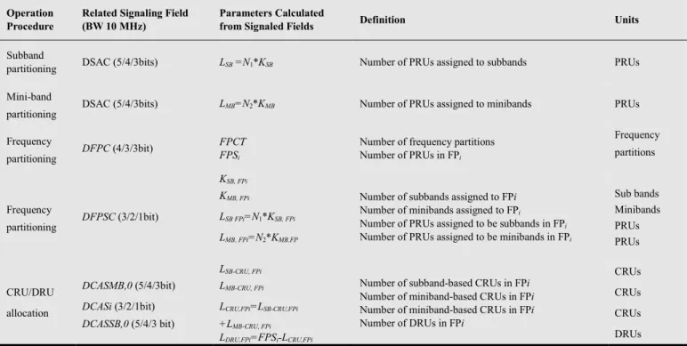
First, we need to calculate summary of the parameters. Table 2 presents a summary of the parameters used to configure the downlink physical structure. In other words, these parameters are used to physical and logical unit for resource allocation.
Primitive parameters
The following four primitive parameters characterize the OFDMA symbol:
—BW: The nominal channel bandwidth.
—Nused: Number of used subcarriers (which include the DC subcarrier).
—n: Sampling factor. This parameter, in conjunction with
BW and Nused determines the subcarrier spacing and the useful symbol time.
—G: This is the ratio of CP time to “useful” time. The following values shall be supported: 1/8, 1/16, and 1/4.
Derived parameters
The following parameters are defined in terms of the primitive parameters of 16.3.2.3:
—NFFT: Smallest power of two greater than Nused
—Sampling frequency: Fs=floor(n⋅ BW⁄8000) ×8000
—Subcarrier spacing: ∆f = Fs/NFFT
—Useful symbol time: Tb=1⁄∆f
—CP time: G=Tg⋅Tb
—OFDMA symbol time: Ts= Tb+Tg
—Sampling time: Tb⁄NFFT
Table 2. Some parameters.
Operation Procedure
Related Signaling Field (BW 10 MHz)
Parameters Calculated
from Signaled Fields Definition Units
Subband
partitioning DSAC (5/4/3bits) LSB =N1*KSB Number of PRUs assigned to subbands PRUs
Mini-band
partitioning
DSAC (5/4/3bits) LMB=N2*KMB Number of PRUs assigned to minibands PRUs
Frequency
partitioning
DFPC (4/3/3bit) FPCT
FPSi
Number of frequency partitions Number of PRUs in FPi
Frequency
partitions
Frequency
partitioning
DFPSC (3/2/1bit)
KSB, FPi
KMB, FPi
LSB FPi=N1*KSB, FPi
LMB, FPi=N2*KMB,FP
Number of subbands assigned to FPi
Number of minibands assigned to FPi
Number of PRUs assigned to be subbands in FPi
Number of PRUs assigned to be minibands in FPi
Sub bands Minibands PRUs PRUs CRU/DRU allocation
DCASMB,0 (5/4/3bit)
DCASi (3/2/1bit)
DCASSB,0 (5/4/3 bit)
LSB-CRU, FPi
LMB-CRU, FPi
LCRU,FPi=LSB-CRU,FPi
+LMB-CRU, FPi LDRU,FPi=FPSi-LCRU,FPi
Number of subband-based CRUs in FPi
Number of miniband-based CRUs in FPi
Number of miniband-based CRUs in FPi
Number of DRUs in FPi
CRUs
CRUs
CRUs
DRUs
4. Modeling Optimization Algorithm of
Resource Allocation
A downlink resource mapping algorithms support both localized and distributed subcarriers, subcarriers permutation,
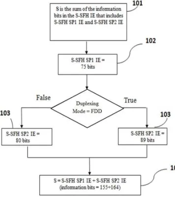
the mapping between LRU and PRU. In addition, we can reduce the information bit of S-SFH 101 by using new algorithm.
three sub-packets (S-SFH SP1 102,S-SFH SP2 103,S-SFH SP3). The sub-packets of S-SFH are transmitted periodically where each sub-packet has a different transmission periodicity (Fig. 4).
Figure 4. Optimization Algorithm.
The SFH occupies the first NSFH distributed LRUs in the
first AAI sub frame of a super frame where NSFH is no more
than 24. The remaining distributed LRUs in the first AAI sub frame of a super frame are used for other control and data transmission. The SFH is divided into two parts: Primary Super frame Header (P-SFH) and Secondary Super frame Header (S-SFH) (101).
Table 2 includes the parameters and values for resource allocation of the SFH.
Some source code for new algorithm of resource allocation: for(i=0; i<FPCT(); i++)
{ for(j=0;j<Lcrufp[i];j++)
{ Prusm4[ind+j]=Prusm3[ind+j]; } ind=ind+Lcrufp[i];
SetPremSeq(FPS[i]-Lcrufp[i]); for(j=0;j<Ldrufp[i];j++)
{ jj = GetPremSeq ( j+ ( Lcrufp[i] - Lsbcrufp[i] ) ); jj = jj % ( FPS [i]-Lsbcrufp [i]);
Prusm4[ind+j] = Prusm3[ind+jj]; } ind=ind+Ldrufp[i]; }
“Fig. 5” shows the flowchart of the miniband permutation, which is used to our research.
Figure 5. Sub band and Miniband partition’s flowchart.
5. Conclusions
The novel resource allocation algorithm in uplink and downlink is proposed to optimize resource allocation procedure for use in 802.16m system. A downlink resource mapping algorithms supports both localized and distributed sub carriers, subcarrier permutation, the mapping between LRU and PRU, supports different fractional frequency reuse (FFR) group allocations. In a future work to developing that algorithm we can possible to reduce redundancy of transmitted control bit field in super frame header.
By using this algorithm, we may be reduce information bit by 10 bits.
References
[1] 3GPP TS 36.211; LTE; Evolved Universal Terrestrial Radio Access (E-UTRA); Physical channels and modulation (version 11.1.0 Release 11)
[2] Harri Holma, Antti Toskala, “LTE for UMTS-OFDMA and SC-FDMA Based Radio Access”, pp. 71, John Wiley & Sons Ltd, 2009
[4] Otgonbayar Bataa, Bat-Enkh Oyunbileg, Baatarkhuu Tsagaan, “A Resource Allocation for Mobile IPTV”, ICKI 2011, Proceedings of International Conference on knowledge Based Industry, Ulaanbaatar, Mongolia
[5] IEEE P802.16m/D7 July 2010, DRAFT Amendment to IEEE Standard for Local and metropolitan area networks, Part 16: Air Interface for Broadband Wireless Access Systems, July 29, (2010)
[6] IEEE 802.16m System Description Document, IEEE 802.16m-08/003r9a, (2009)
[7] IEEE 802.16m Evaluation Methodology Document (EMD), January 15, (2009)