INTELLIGENT NETWORKS
Introduction to SS7 Signaling (Protocols)
Lecturer:
SS7 P
ROTOCOL
L
AYERS
SS7 P
ROTOCOL
L
AYERS
Physical Layer
This defines the physical and electrical characteristics of the signaling links of the SS7 network. Signaling links utilize DS–0 channels and carry raw signaling data at a rate of 56 kbps or 64 kbps (56 kbps is the more common implementation).
Message Transfer Part – Level 2
The level 2 portion of the message transfer part (MTP Level 2) provides link-layer functionality. It ensures that the two end points of a signaling link can reliably exchange signaling messages. It incorporates such capabilities as error checking, flow control, and sequence checking.
Message Transfer Part – Level 3
SS7 P
ROTOCOL
L
AYERS
Signaling Connection Control Part
The signaling connection control part (SCCP) provides two major functions
that are lacking in the MTP.
The first of these is the capability to address applications within a signaling point. The MTP can only receive and deliver messages from a node as a whole; it does not deal with software applications within a node.
While MTP network-management messages and basic call-setup messages are addressed to a node as a whole, other messages are used by separate applications (referred to as subsystems) within a node.
SS7 P
ROTOCOL
L
AYERS
Global Title Translation
The second function provided by the SCCP is the ability to perform incremental routing using a capability called global title translation (GTT). GTT frees originating signaling points from the burden of having to know every potential destination to which they might have to route a message. A switch can originate a query, for example, and address it to an STP along with a request for GTT. The receiving STP can then examine a portion of the message, make a determination as to where the message should be routed, and then route it.
SS7 P
ROTOCOL
L
AYERS
For example, calling-card queries (used to verify that a call can be properly billed to a calling card) must be routed to an SCP designated by the company that issued the calling card. Rather than maintaining a nationwide database of where such queries should be routed (based on the calling-card number), switches generate queries addressed to their local STPs, which, using GTT, select the correct destination to which the message should be routed.
Note that there is no magic here; STPs must maintain a database that enables them to determine where a query should be routed. GTT effectively centralizes the problem and places it in a node (the STP) that has been designed to perform this function.
SS7 P
ROTOCOL
L
AYERS
ISDN User Part (ISUP)
The ISUP user part defines the messages and protocol used in the establishment and tear down of voice and data calls over the public switched network (PSN), and to manage the trunk network on which they rely. Despite its name, ISUP is used for both ISDN and non−ISDN calls. In the North American version of SS7, ISUP messages rely exclusively on MTP to transport messages between concerned nodes.
Transaction Capabilities Application Part (TCAP)
SS7 P
ROTOCOL
L
AYERS
Operations, Maintenance, and Administration Part (OMAP)
W
HAT
G
OES
O
VER THE
S
IGNALING
L
INK
Signaling information is passed over the signaling link in messages, which are called signal units (SUs).
Three types of SUs are defined in the SS7 protocol:
message signal units (MSUs);
link status signal units (LSSUs);
fill-in signal units (FISUs).
W
HAT
G
OES
O
VER THE
S
IGNALING
L
INK
All transmission on the signaling link is broken up into 8-bit bytes, referred to as octets. SUs on a link are delimited by a unique 8-bit pattern known as a
flag. The flag is defined as the 8-bit pattern:
01111110
Because of the possibility that data within an SU would contain this pattern, bit manipulation techniques are used to ensure that the pattern does not occur within the message as it is transmitted over the link. (The SU is reconstructed once it has been taken off the link, and any bit manipulation is reversed.) Thus,
any occurrence of the flag on the link indicates the end of one SU and the beginning of another.
B
ASIC
S
IGNALING
A
RCHITECTURE
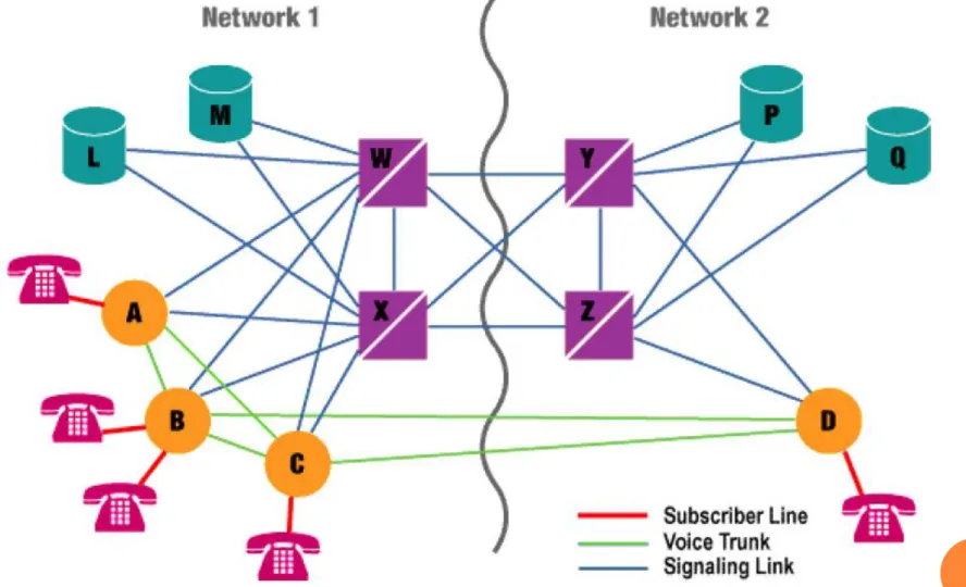
Figure 1 shows a small example of how the basic elements of an SS7 network are deployed to form two interconnected networks.
B
ASIC
S
IGNALING
A
RCHITECTURE
The following points should be noted:
1. STPs W and X perform identical functions. They are redundant. Together, they are referred to as a mated pair of STPs. Similarly, STPs Y and Z form a mated pair.
2. Each SSP has two links (or sets of links), one to each STP of a mated pair. All SS7 signaling to the rest of the world is sent out over these links. Because the STPs of a mated pair are redundant, messages sent over either link (to either STP) will be treated equivalently.
3. The STPs of a mated pair are joined by a link (or set of links).
4. Two mated pairs of STPs are interconnected by four links (or sets of links). These links are referred to as a quad.
5. SCPs are usually (though not always) deployed in pairs. As with STPs, the SCPs of a pair are intended to function identically. Pairs of SCPs are also referred to as mated pairs of SCPs. Note that they are not directly joined by a pair of links.
B
ASIC
C
ALL
S
ETUP
E
XAMPLE
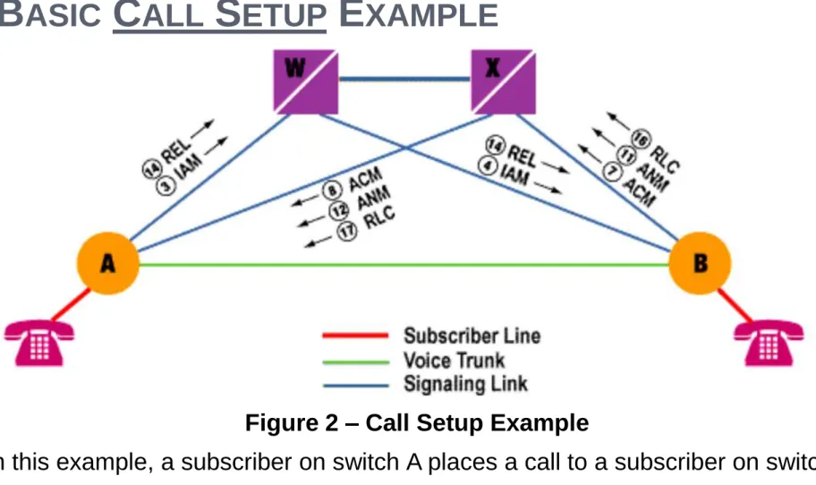
Figure 2 – Call Setup Example
In this example, a subscriber on switch A places a call to a subscriber on switch B.
B
ASIC
C
ALL
S
ETUP
E
XAMPLE
2. Switch A selects an idle trunk between itself and switch B and formulates an initial address message (IAM), the basic message necessary to initiate a call. The IAM is addressed to switch B. It identifies the initiating switch (switch A), the destination switch (switch B), the trunk selected, the calling and called numbers, as well as other information beyond the scope of this example.
3. Switch A picks one of its A links (e.g., AW) and transmits the message over the link for routing to switch B.
4. STP W receives a message, inspects its routing label, and determines that it is to be routed to switch B. It transmits the message on link BW.
5. Switch B receives the message. On analyzing the message, it determines that it serves the called number and that the called number is idle.
B
ASIC
C
ALL
S
ETUP
E
XAMPLE
7. Switch B picks one of its A links (e.g., BX) and transmits the ACM over the link for routing to switch A. At the same time, it completes the call path in the backwards direction (towards switch A), sends a ringing tone over that trunk towards switch A, and rings the line of the called subscriber.
8. STP X receives the message, inspects its routing label, and determines that it is to be routed to switch A. It transmits the message on link AX.
9. On receiving the ACM, switch A connects the calling subscriber line to the selected trunk in the backwards direction (so that the caller can hear the ringing sent by switch B).
10. When the called subscriber picks up the phone, switch B formulates an answer message (ANM), identifying the intended recipient switch (A), the sending switch (B), and the selected trunk.
B
ASIC
C
ALL
S
ETUP
E
XAMPLE
12. STP X recognizes that the ANM is addressed to switch A and forwards it over link AX.
13. Switch A ensures that the calling subscriber is connected to the outgoing trunk (in both directions) and that conversation can take place.
14. If the calling subscriber hangs up first (following the conversation), switch A will generate a release message (REL) addressed to switch B, identifying the trunk associated with the call. It sends the message on link AW.
15. STP W receives the REL, determines that it is addressed to switch B, and forwards it using link WB.
16. Switch B receives the REL, disconnects the trunk from the subscriber line, returns the trunk to idle status, generates a release complete message (RLC) addressed back to switch A, and transmits it on link BX. The RLC identifies the trunk used to carry the call.
17. STP X receives the RLC, determines that it is addressed to switch A, and forwards it over link AX.
D
ATABASE
Q
UERY
E
XAMPLE
People generally are familiar with the toll-free aspect of 800 (or 888) numbers, but these numbers have significant additional capabilities made possible by the SS7 network. 800 numbers are virtual telephone numbers. Although they are used to point to real telephone numbers, they are not assigned to the subscriber line itself.
When a subscriber dials an 800 number, it is a signal to the switch to suspend the call and seek further instructions from a database. The database will provide either a real phone number to which the call should be directed, or it will identify another network (e.g., a long-distance carrier) to which the call should be routed for further processing. While the response from the database could be the same for every call (as, for example, if you have a personal 800 number), it can be made to vary based on the calling number, the time of day, the day of the week, or a number of other factors.
D
ATABASE
Q
UERY
E
XAMPLE
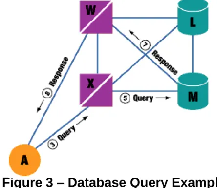
Figure 3 – Database Query Example
1. A subscriber served by switch A wants to reserve a rental car at a company's nearest location. She dials the company's advertised 800 number.
2. When the subscriber has finished dialing, switch A recognizes that this is an 800 call and that it requires assistance to handle it properly.
D
ATABASE
Q
UERY
E
XAMPLE
4. STP X determines that the received query is an 800 query and selects a database suitable to respond to the query (e.g., M).
5. STP X forwards the query to SCP M over the appropriate A link (MX). SCP M receives the query, extracts the passed information, and (based on its stored records) selects either a real telephone number or a network (or both) to which the call should be routed.
6. SCP M formulates a response message with the information necessary to properly process the call, addresses it to switch A, picks an STP and an A link to use (e.g., MW), and routes the response.
7. STP W receives the response message, recognizes that it is addressed to switch A, and routes it to A over AW.
A
DDRESSING IN THE
SS7 N
ETWORK
Every network must have an addressing scheme, and the SS7 network is no different. Network addresses are required so that a node can exchange signaling nodes to which it does not have a physical signaling link.
In SS7, addresses are assigned using a three-level hierarchy.
1. Individual signaling points are identified as belonging to a cluster of signaling points.
2. Within that cluster, each signaling point is assigned a member number. 3. Similarly, a cluster is defined as being part of a network.
A
DDRESSING IN THE
SS7 N
ETWORK
S
IGNAL
U
NIT
S
TRUCTURE
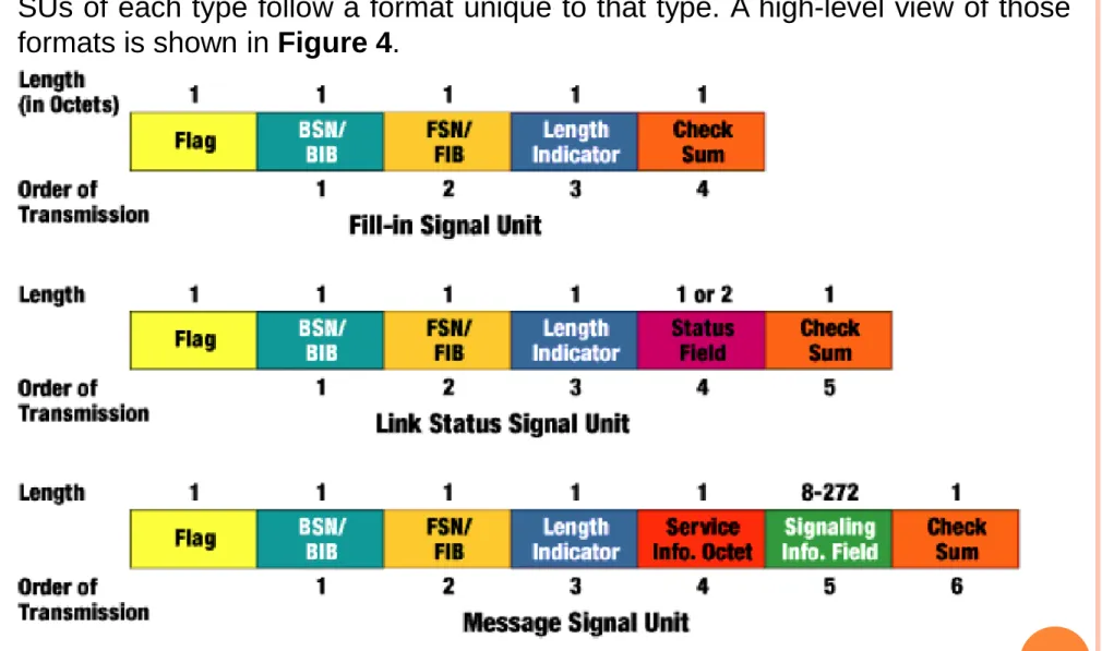
SUs of each type follow a format unique to that type. A high-level view of those formats is shown in Figure 4.
S
IGNAL
U
NIT
S
TRUCTURE
All three SU types have a set of common fields that are used by MTP Level 2. They are as follows:
Flag
Flags delimit SUs. A flag marks the end of one SU and the start of the next.
Checksum
The checksum is an 8-bit sum intended to verify that the SU has passed across the link error-free. The checksum is calculated from the transmitted message by the transmitting signaling point and inserted in the message. On receipt, it is recalculated by the receiving signaling point. If the calculated result differs from the received checksum, the received SU has been corrupted. A retransmission is requested.
Length Indicator
S
IGNAL
U
NIT
S
TRUCTURE
BSN/BIB FSN/FIB
These octets hold the backwards sequence number (BSN), the backwards indicator bit (BIB), the forward sequence number (FSN), and the forward indicator bit (FIB). These fields are used to confirm receipt of SUs and to ensure that they are received in the order in which they were transmitted. They also are used to provide flow control. MSUs and LSSUs, when transmitted, are assigned a sequence number that is placed in the forward sequence number field of the outgoing SU. This SU is stored by the transmitting signaling point until it is acknowledged by the receiving signaling point.
W
HAT ARE THE
F
UNCTIONS OF THE
D
IFFERENT
S
IGNALING
U
NITS
?
FISUs themselves have no information payload. Their purpose is to occupy the link at those times when there are no LSSUs or MSUs to send. Because they undergo error checking, FISUs facilitate the constant monitoring of link quality in the absence of signaling traffic. FISUs also can be used to acknowledge the receipt of messages using the backwards sequence number and backwards indicator bit.
W
HAT ARE THE
F
UNCTIONS OF THE
D
IFFERENT
S
IGNALING
U
NITS
?
M
ESSAGE
S
IGNAL
U
NIT
S
TRUCTURE
The functionality of the message signal unit lies in the actual content of the service information octet and the signaling information field (see Figure 4).
The service information octet is an 8-bit field (as might be inferred from its name) that contains three types of information as follows:
1. Four bits are used to indicate the type of information contained in the signaling information field; they are referred to as the service indicator; the values most commonly used in American networks are outlined in Table 1.
2. Two bits are used to indicate whether the message is intended (and coded) for use in a national or international network; they are generally coded with a value of 2, national network.
3. The remaining 2 bits are used (in American networks) to identify a message priority, from 0 to 3, with 3 being the highest priority; message priorities do not control the order in which messages are transmitted; they are only used in cases of signaling network congestion; in that case, they indicate whether a message has sufficient priority to merit transmission during an instance of congestion or whether it can be discarded en route to a destination.
M
ESSAGE
S
IGNAL
U
NIT
S
TRUCTURE
M
ESSAGE
S
IGNAL
U
NIT
S
TRUCTURE
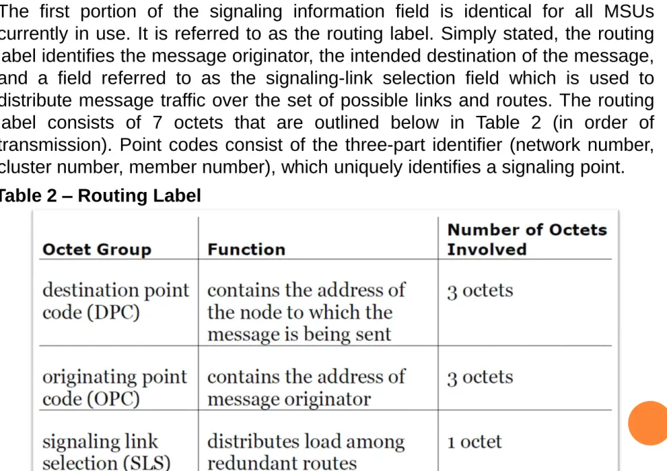
The first portion of the signaling information field is identical for all MSUs currently in use. It is referred to as the routing label. Simply stated, the routing label identifies the message originator, the intended destination of the message, and a field referred to as the signaling-link selection field which is used to distribute message traffic over the set of possible links and routes. The routing label consists of 7 octets that are outlined below in Table 2 (in order of transmission). Point codes consist of the three-part identifier (network number, cluster number, member number), which uniquely identifies a signaling point.