ISSN: 2252-8938, DOI: 10.11591/ijai.v9.i3.pp545-552 545
Design and implementation of wireless system for vibration
fault detection using fuzzy logic
Moneer Ali Lilo1, Maath Jasem Mahammad21Department of Chemical Engineering, Al Muthanna University, Iraq 2Department of Electrical Engineering, University of Anbar, Iraq
Article Info ABSTRACT
Article history: Received Apr 20, 2020 Revised Jun 7, 2020 Accepted Jun 13, 2020
This paper presents the wireless system for fault detection and monitoring based on fuzzy logic technique. Wireless applications are utilized to identify, classify, and monitor faults in the real time to protect machines from damage. Two schemes were tested; first scheme fault collected X-Y-Z-axes mode while the second scheme collected Y-axis mode, which is utilized to protect the induction motor (IM) from vibrations fault. The vibration signals were processed in the central computer to reduce noise by signal processing stage, and then the fault was classified and monitored based on Fuzzy Logic (FL). The wireless vibration sensor was designed depending on the wireless techniques and C++ code. A fault collection, noise reduction, vibration fault classification and monitoring were implemented by MATLAB code. In the second scheme the processed real time was reduced to 60%, which is included collection, filtering, and monitoring fault level. Results showed that the system has the ability to early detect the fault occurrence on the machine with processing time of 1.721s. This work will reduce the maintenance cost and provide the ability to utilize the system with harsh industrial applications to diagnose the fault in real time processing.
Keywords: Fault detection Fuzzy logic
Real time processing Signals processing Wireless sensor
This is an open access article under the CC BY-SA license.
Corresponding Author: Maath Jasem Mahammad,
Department of Electrical, College of Engineering, University of Anbar, Iraq.
Email: [email protected]
1. INTRODUCTION
Induction motor (IM) is important in industrial applications. It can be utilized as a prime mover for the electricity generation. However, the vibration fault spreads throughout the machine and subsequently damages the system if it is high enough. Researches proposed the reduction, prevention, and monitoring of the fault level based on specific conditions [1-2]. The vibration fault is a neutral phenomenon linked to static and dynamic systems. It is also proportional to the load applied on the machine and speed [3-4]. Most researches intended to protect the machine from damages by monitoring the fault and shutting down the system, especially if the fault lies in the dangerous zone. These processes lead to the reduction of maintenance costs as it saves the machine from damages [5].
The wireless technique uses electromagnetic waves for the transceiver of the data. With electromagnetic waves, intended distances can be far, such as kilometers for space radio communications or as short, as Bluetooth. The electromagnetic includes different kinds of fixed, mobile and portable applications. Recently, the Wireless technique was used in many applications such as data sands for the camera, robotic control, fault, and wirelessly power transmission [6-7]. There are many standards utilized for transceiver data with wireless sensor network where selecting standards
will be based on the power consumption, the distance of the transceiver, frequency band, and wireless network applications [8-9]. Industrial wireless sensor networks (IWSNs), such as ZigBee, IEEE 802.15.4, and ISA100 were utilized in many applications to augment the flexibility of data collection and reduce the cost of system implementation [10-12]. Researchers relied on IEEE standards such as ZigBee, and ISA 100 to gather data from industrial and greenhouse applications [13-14].
Recently, IWSN hybridized with artificial intelligence (AI) techniques such as Neural Network (NN), Fuzzy Logic (FL), and Support Vector Machine (SVM) to implement smart wireless systems [15-16]. AI was used owing to its capability for signal identification and classification in a time or a frequency domain [17-18].
Fuzzy Logic was used to describe the machine behaviors by classifying the systems’ situation during the real time processing [19-20]. Fuzzy logic is a widely used wideband for control and protection enhance system behavior [21-22]. Some proposals were focused on hybrid fuzzy logic with other techniques for precision improvement of the system control, and decision making for with the protection system [23-25]. Many researches were interested in classifying and identifying the fault by a central computer after the data is collected via wireless sensors for monitoring, analyzing, and controlling [26-27]. The Vibration Fault Diagnosis of a machine may use different methodologies to save the machine from damage such as fuzzy, neural and support vector machine [28-30]. While this methodologies hybrid with wireless technology to improve the system applications for industrial and be utilized with a harsh environment [31].
In [32], author proposed a new scheme using a wireless sensor to improve the protection of the wind turbine from vibration faults based on the prediction and classification of vibration faults. This work did not focus on artificial intelligent technique for the fault detection. In [33] implemented a wireless sensor that has the ability to detect low-frequency values and low-amplitude of acceleration. The design depended on the conversion of the outputs of the physical sensor from voltage to frequency. The conventional method depends on transferring data from analog-to-digital, while new method (transfer voltage to frequency) increases the accuracy and sensitivity of the fault detection. However, [33] limited by errors, wireless protocol, and operating range which is designed for a short distance for applications of civil engineering. In [34] developed a system to measure the vibrations fault utilizing android devices connected via Bluetooth. Data were evaluated in the main database and fed to the portable box for controlling another system. The Bluetooth needs high power and does not use for far distance applications which are represented weak of design.
In [35] proposed a wireless system to control the vibration fault on the beam. The vibration fault signal was analyzed on a central computer to generate signal for reducing the beam vibration. The real time response and reliability were improved based on the wireless technique. The system was utilized for controlling the static vibration and not used fuzzy or neural of fault analysis. In [36], author presented a system based on the neural technique to diagnose the vibration fault level, where the data was gathered from a machine within the nodes. By augmenting the sampling rate for the gathering data, the real time processing was prolonged. The system was interested in the consumption power and found a new topology for the WSN considering that the fault detection accuracy was not improved.
A system to identify and classify the vibration fault to influence the protection of the machine was presented by [15]. The system was implemented using wireless sensors, signal processing, neural, fuzzy, and decision card. 512 bytes are related to vibration fault in three axes and speed value, which are collected from the WSN. Also, the system relies on the two stages of the AI (neural, fuzzy) to identify the faults arising in the machine. The time process of data collecting, filtering, and analyzing is 5.892s, for fault detection.
This work intends to design a wireless system to detect the real time vibration fault based on a fuzzy technique. It can be used to protect the induction motor from the vibration fault that may destroy the machine if it is being in high level. The system monitors the vibration fault after detecting by applying vibration data to fuzzy. Moreover, the real time process is improved based on the wireless and fuzzy technique to be 4.501s for collecting data in 3-axis mod. The rest of this paper is organized in the following order: the first section describes the introduction and related works, the second section presents the methodological design, and the third section shows complete system design. While, in the fourth section the results, the last section concludes the work.
2. METHODOLOGY
In this work, the system is implemented via two codes; the first is linked to C++, which is used to design and implement the Wireless Vibration Sensor (WVS) and wireless speed sensor (WSS). The WSS sends the speed data to WVS, and the data will be collected from the induction motor via WVS as a one packet after modifying the data of speed and vibration in one packet. The second code involves MATLAB to design the signal processing and fuzzy logic stages. These stages are used to reduce the noise, transfer the
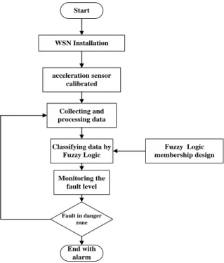
signal to frequency domain, and identify and classify the fault in the main computer. Finally, the integrated system has the ability to detect level of the vibration fault and alarm user if the fault is in danger or alarm zone. Figure 1 shows the flow chart the system.
Figure 1. Flow chart of methodology and material
Complete System Design
The scheme has been designed to represent wireless system for fault detections shown in Figure 1. This section provides details pertaining to each part of the system.
2.1. Wireless sensor network implementation
Two wireless sensors were used to collect the data from the machine and one coordinator, which feeds the data to the main computer. The first sensor is WVS, which was used to collect vibration data in three and one axes. The second sensor was WSS and it was used to collect the speed data of the machine. These sensors (WVS, WSS) were constructed based on the microcontroller type ATmega328, the ZigBee based on the IEEE802.15.4 PHY and MAC layers, Lithium battery, and physic sensor. The difference between the WVS and WSS is related to the physical sensor. , WVS exhibited an acceleration sensor, while, WSS used a magnetic field sensor in the WSS to collect speed data. Actually, the data of the vibration fault and the speed of the machine will be prepared as a one packet within the vibration sensor before sending. Finally, the main computer collects data from WSN via a coordinator that is connected with computers as a one packet containing the acceleration and speed values.
2.2. Signal processing stage
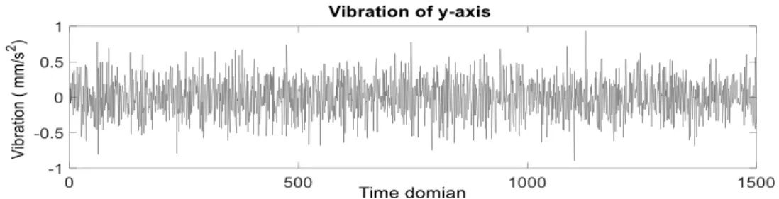
The raw data of vibration fault contain noise(s) as shown in Figure 2 owing to the electromagnetic devices, which causes errors in the fault amplitude. The data need to be filtered in order to reduce noise based on the band pass filter (BPF). Thereafter, vibration fault signal shows on the resonant frequency for the selected speed. Thus, the low pass filter (LPF) is utilized to display the fault signal in these frequencies. Then, the vibration fault signals post-filtration are transferred to the frequency domain using the fast Fourier transform (FFT) algorithm [37].
Start
WSN Installation
acceleration sensor calibrated
Collecting and processing data
Classifying data by Fuzzy Logic
Monitoring the fault level
Fault in danger zone
End with alarm
Fuzzy Logic membership design
Figure 2. Raw vibration fault for the Y-axis collected from wireless sensor
2.3. Fuzzy logic and monitoring stage
The data resulted from the signal processing stage will be fed to the fuzzy logic for identifying and classifying vibration fault level on IM. In this work, the Sugeno Fuzzy Inference System (SFIS) was selected to monitor the fault case, if the vibration fault occurs in the severity or alarm zone. Actually, the fuzzy system was used to apply the condition monitoring to protect the IM from vibration faults. The fuzzy system is designed with two inputs that are related to the vibration fault and the speed of the machine. The fuzzy output is represented by one output to classify and identify the fault level, as shown in Figure 3. The main objective of using fuzzy logic to dragons and classify vibration fault level. Thus, the “expert experience” of a human worker in industrial filed and the ISO 10816-2 for vibration conditions is incorporated in a process whose input-output relationship is described by a collection of fuzzy rules, as shown in Table 1. Where RSV is the (reduce value) of speed, and SHD is mean shut down system. The speed value of the machine was used due to the vibration fault being affected by the speed of the machine [37].
Table 1. Rule of the fuzzy logic
SPEED (rpm)
125> 175 >185
V
ib
ra
ti
o
n
zo
n
e
normal Accp. Accp. Accp.
Alarm1 RV1 RV2 RV3
Alarm2 RV2 RV3 RV4
Alarm3 RV3 RV4 RV5
Danger SHD SHD SHD
(a) (b)
Figure 3. (a) Fuzzy system construction (b) fuzzy membership functions
3. RESULT AND DISCUSSION
The acceleration data collected from the plate form will be collected in a time domain with a large amount of noise, as shown in Figure 2 considering that the acceleration is expressed in mm/s2.
3.1. Time processing of the system
The acceleration and speed data were collected from the wireless sensors network. The main challenges for using the wireless sensor technique are the packet loss and real time needed to gather the data. Notably, the packet loss in the industrial environment is preoperational to the distance of the nodes, while the real time depends on the length of the data [15, 38]. It seems that the scheme is used to manage data collection from WSN to improve the reliability of the system. This scheme collects the data from the router as a one packet made up of the acceleration and speed data. In the main computer, the data will be separated to the acceleration data that are used in signal processing stage, while the speed values will be fed to the fuzzy stage to confirm the decision. The packet length in this work is 385 integer value of acceleration and one value of speed for RPM, X, Y, Z-axis scheme. The real time processing will be improved owing to the collected one value of speed every 129 values of acceleration for RPM, Y-axis scheme. The real time needed to collect the packets that are contained in these data are related to 128*3 samples, and the one value of speed is 4.45 s. Moreover, the real time processing of gathering data with length 129 for acceleration and one value of speed is 1.67 s. These values are depicted in Table 2. The real-time processing in this work was reduced by 30% comparison with [15]. That time processing is related to data processing of the three axes scheme.
Table 2. Time processing of the two schemes
Scheme collection
Packet length
Time collection via MATLAB (s)
Fuzzy processing(s)
Computer Bud Rate
Samples/time (Sampling rate)
Sensor convenient
Time processing Overall (s) RPM,X,Y, Z 385 4.45 0.051 19200 88.8 0 ~40 Hz 4.501
RPM, Y 129 1.67 0.051 19200 88.8 0 ~ 40 Hz 1.721
3.2. Signal processing stage
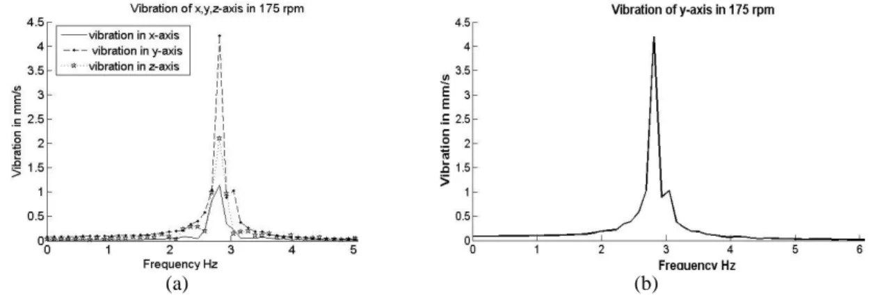
The data from the WSN stage will be fed to the signal processing stage to reduce the noise collected with the raw data via using the Low Pass Filter (LPF) and Band Pass Filter (BPF). The final data from the filtration will transfer the frequency demine using the FFT technique. Three modes of vibration signal which are velocity, acceleration and displacement. The velocity mode is represented the vibration fault in this work. The velocity (velocity vibration fault mode) data is expressed in mm/s. The results shown in Figure 4 are the vibration fault values after being filtered and converted by LPF, BPF, and FFT, where the resonant frequency of the IM is (175 rpm). Figure 4(a) shows the result of the signal processing stage for the first scheme which is collected the RPM, X, Y, Z- axis, while, Figure 4(b) shows the result after processing the raw data of second scheme that is collected the RPM, Y- axis. The vibration fault amplitudes were calculated based on (1), while the speed of IM is measured as frequency based on (2).
(1)
(2) where a denotes the acceleration mode of vibration fault, 𝜔 = 2𝜋𝑓 , and 𝒇 is the frequency of the machine (Hz) [15].
(a) (b)
Figure 4. Result of signal processing stage (a) X,Y,Z-axes (b) for the Y-axis scheme
sin
a
A
t
speed rpm 60 f
3.3. Fuzzy logic stage throughput
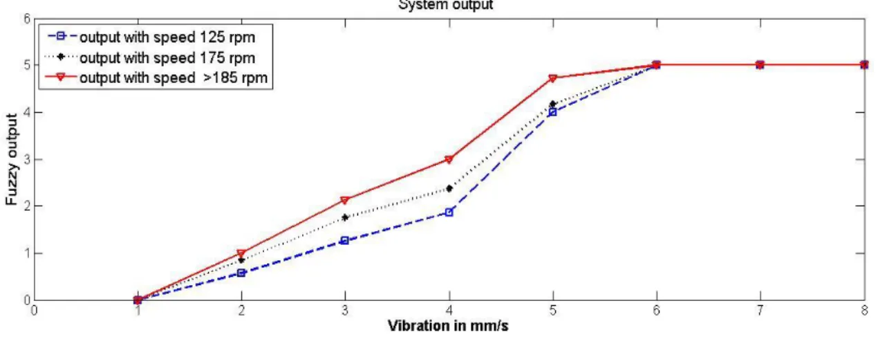
In this work, the sugeno FIS technique was constructed to classify and identify the fault levels based on different conditions. The fuzzy technique was implemented using two input membership functions (MFs); the first MF was designed based on conditions of ISO 10816-3 to identify and classify the vibration faults, while the second described the IM speed. The output MF was constructed to classify the vibration fault level, as shown in Figure 3. The main purpose of using the Fuzzy technique is to classify the fault situations. Also, fuzzy result will generate linear signals as shown in Figure 5 to represent non-linear behavior system as shown in Figure 2. Thus, the output result from fuzzy provides the stability of the machine control. The signal of fuzzy can be fed to the control system for protecting the machine from fault if it is in the danger zone.
The results of this research show that real time processing decreased to 1.721s if the vibration fault was collected with one axis only, as shown in Table 2. This process will improve the real time protection and condition monitoring for machine fault diagnosis. On the other hand, the collected three axes of the vibration fault will increase the accuracy of the fault detection which is used for fault analysis and protects the expensive machine.
Finally, the fuzzy output with different speed values show that the vibration fault is successfully identified by fuzzy logic. Comparing the values in Figures 2 and 5 allows us to elucidate the improvement of the system behavior to produce smooth signal (fuzzy output) to represent complex signals (raw vibration fault) and successfully identify and classify the vibration fault during real time processing. Thus, these system throughputs can be used with the protection systems without interfering with the control system stability.
Figure 5. System output with different speeds value
4. CONCLUSIONS
This work involves the vibration and speed data collection from wireless vibration sensor and wireless speed sensor. Data collected are processed in main computer to diagnose and classify the vibration fault based on signal processing and fuzzy logic in real time processing. These process products the induction motor from vibration fault if it is in the danger level. Reducing noise and transferring the signal to the frequency domain which is done via signal processing. Thus, the vibration fault was identified and classified by the Fuzzy logic. Two schemes were utilized to collect data based on vibration data mode in 1-axis and 3-axis. The results of the two schemes show collecting data in 1-axis is better than 3-axis based on real time processing. Moreover, the fault was detection and prediction accuracy of vibration fault in 3-axis better than in 1-axis scheme. In addition, the real time processing of this work was improved 30% with same accuracy of fault diagnose. Thus, fault can be detected even reduce packet length for improve the real time processing. Moreover, fault diagnoses successfully based on utilized signal processing and fuzzy logic technique. The usage of the wireless technique enhances the system’s reliability, flexibility, and cost decrease.
REFERENCES
[1] L. Hou and N. W. Bergmann, “Induction Motor Fault Diagnosis Using Industrial Wireless Sensor Networks and
Dempster-Shafer Classifier Fusion,” in 2011IEEE Industrial Electronics Society, Conf. of IECON2011, pp. 2992-2997.
[2] Y. Yu, W. Li, D. Sheng, and J. Chen, “A novel sensor fault diagnosis method based on Modified Ensemble
Empirical Mode Decomposition and Probabilistic Neural Network,” Measurement, vol. 68, pp. 328-336, 2015.
[3] M. A. Lilo, L. A. Latiff, A. Bin Haji Abu, Y. I. Al Mashhadany, and A. K. Ilijan, “Gas Turbine Bearing and Vibration Classification of Using Multi-layer Neural Network,” IEEE Conf. ICSSA2015, pp. 3-6, 2015.
[4] X. Zhang, Y. Liang, J. Zhou, and Y. Zang, “A novel bearing fault diagnosis model integrated permutation entropy,
ensemble empirical mode decomposition and optimized SVM,” Measurement, vol. 69, pp. 164-179, 2015.
[5] M. A. L. I. Lilo, L. A. Latiff, A. Bin, and H. Abu, “Identify and Classify Vibration Fault Based on Artificial Intelligence Techniques,” vol. 94, no. 2, pp. 464-474, 2016.
[6] H. A. Kadhim, N. S. Ali, and D. M. Abdulsahib, “Management and archiving system for metal detection robot using wireless-based technology and online database registry,” Int. J. Power Electron. Drive Syst., vol. 10, no. 1, p. 219, 2019.
[7] A. Ali, M. N. Yasin, M. F. C. Husin, and N. A. A. Hambali, “Design and analysis of 2-coil wireless power transfer (WPT) using magnetic coupling technique,” Int. J. Power Electron. Drive Syst., vol. 10, no. 2, p. 611, 2019.
[8] M. Tjensvold, “Comparison of the IEEE 802.11, 802.15. 1, 802.15. 4 and 802.15. 6 wireless standards. Sep 2007,”
Com/2008/07/Comparison-Ieee-802-Standards. PDF, no. 1, pp. 1-7, 2007.
[9] M. Nixon, “A Comparison of WirelessHARTTM and ISA100. 11a,” white Pap. July, pp. 1-36, 2012.
[10] M. A. Lilo, L. A. Latiff, A. Bin, H. Abu, Y. I. Al Mashhadany, and S. M. A. Al-, “Design of Industrial Wireless
Sensor System for Real-Time Data Collection in Steam Turbines,” in SCOPUS -2015 International Conference on
Computer Systems and Instrumentation, 2015.
[11] G. Zhang, C. a. Duncan, J. Kanno, and R. R. Selmic, “Unmanned Ground Vehicle Navigation in Coordinate-Free and Localization-Free Wireless Sensor and Actuator Networks,” J. Intell. Robot. Syst., vol. 74, no. 3-4, pp. 869-891, 2014.
[12] L. Hou and N. W. Bergmann, “Novel industrial wireless sensor networks for machine condition monitoring and fault diagnosis,” IEEE Trans. Instrum. Meas., vol. 61, no. 10, pp. 2787-2798, 2012.
[13] I. Jawhar, N. Mohamed, J. Al-Jaroodi, and S. Zhang, “A Framework for Using Unmanned Aerial Vehicles for Data Collection in Linear Wireless Sensor Networks,” J. Intell. Robot. Syst., vol. 74, no. 1-2, pp. 437-453, 2014. [14] V. C. Gungor, G. P. Hancke, and S. Member, “Industrial Wireless Sensor Networks : Challenges , Design
Principles , and Technical Approaches,” 4258 IEEE Trans. Ind. Electron., vol. 56, no. 10, pp. 4258-4265, 2009. [15] M. Lilo, L.A.Latiff, A. Abu, and Y. Al Mashhadany, “Wireless Fault Tolerances Decision Using Artificial
Intelligence Technique,” J. Theor. Appl. Inf. Technol., vol. 87, no. 2, pp. 324-335, 2016.
[16] X. Lei, P. Lu, and F. Liu, “The high performance control for small rotary-wing unmanned aircraft based on composite control method,” Trans. Inst. Meas. Control, vol. 36, no. 8, pp. 1033-1040, 2014.
[17] S. Yusuf, S. Shetty, N. Wilkinson, and D. J. Brown, “A novel self-configuring ethernet-based smart sensor application for remote condition monitoring,” Mob. Embed., 2013.
[18] S. K. Jha, K. Hayashi, and R. D. S. Yadava, “Neural, fuzzy and neuro-fuzzy approach for concentration estimation of volatile organic compounds by surface acoustic wave sensor array,” Measurement, vol. 55, pp. 186-195, 2014. [19] A. S. Weddell, G. V. Merrett, S. Barrow, and B. M. Al-Hashimi, “Vibration-powered sensing system for engine
condition monitoring,” in IET conference Publications, 2012.
[20] R. K. Barai and K. Nonami, “Locomotion Control of a Hydraulically Actuated Hexapod Robot by Robust Adaptive
Fuzzy Control with Self-Tuned Adaptation Gain and Dead Zone Fuzzy Pre-compensation,” J. Intell. Robot. Syst.,
vol. 53, no. 1, pp. 35-56, 2008.
[21] A. Mousmi, A. Abbou, and Y. El Houm, “Real-time implementation of a novel hybrid fuzzy sliding mode control of a BLDC motor,” Int. J. Power Electron. Drive Syst., vol. 10, no. 3, p. 1167, 2019.
[22] N. Farah, M. H. N. Talib, Z. Ibrahim, J. M. Lazi, and M. Azri, “Self-tuning Fuzzy Logic Controller Based on Takagi-Sugeno Applied to Induction Motor Drives,” Int. J. Power Electron. Drive Syst., vol. 9, no. 4, p. 1967, 2018.
[23] W. I. Hameed, B. A. Sawadi, and A. Muayed, “Voltage Tracking Control of DC- DC Boost Converter Using Fuzzy Neural Network,” Int. J. Power Electron. Drive Syst., vol. 9, no. 4, p. 1657, 2018.
[24] S. R. Reddy, P. V. Prasad, and G. N. Srinivas, “Design of PI and Fuzzy Logic Controllers for Distribution Static Compensator,” Int. J. Power Electron. Drive Syst., vol. 9, no. 2, p. 465, 2018.
[25] A. J. Ali, Z. Farej, and N. Sultan, “Performance evaluation of a hybrid fuzzy logic controller based on genetic algorithm for three phase induction motor drive,” Int. J. Power Electron. Drive Syst., vol. 10, no. 1, p. 117, 2019. [26] E. T. Esfahani, S. Wang, and V. Sundararajan, “Multisensor wireless system for eccentricity and bearing fault
detection in induction motors,” IEEE/ASME Trans. Mechatronics, vol. 19, no. 3, pp. 818-826, 2014.
[27] C. Papachristos, K. Alexis, and A. Tzes, “Dual-Authority Thrust-Vectoring of a Tri-TiltRotor employing Model Predictive Control,” J. Intell. Robot. Syst., 2015.
[28] M. Yaichi, M. K. Fellah, and A. Mammeri, “A neural network based MPPT technique controller for photovoltaic pumping system,” Int. J. Power Electron. Drive Syst., vol. 4, no. 2, pp. 241-255, 2014.
[29] A. Benkada, H. Chaikhy, and M. Monkade, “MPPT Control for Wind Energy Conversion System Based on a T-S Fuzzy,” Int. J. Power Electron. Drive Syst., vol. 9, no. 2, p. 811, 2018.
[30] X. Liu, H. Huang, and J. Xiang, “A Personalized Diagnosis Method to Detect Faults in a Bearing Based on Acceleration Sensors and an FEM Simulation Driving Support Vector Machine,” Sensors, vol. 20, no. 2, p. 420, 2020.
[31] O. Avci, O. Abdeljaber, S. Kiranyaz, and D. Inman, “Convolutional Neural Networks for Real-time and Wireless Damage Detection,” Dyn. Civ. Struct., vol. 2, pp. 129-136, 2020.
[32] A. D. Spacek, O. H. A. Junior, J. M. Neto, V. L. Coelho, M. O. Oliveira, V. Gruber, and L. Schaeffer, “Management of Mechanical Vibration and Temperature in Small Wind Turbines Using Zigbee Wireless Network,” ILATIN Am. Trans. IEEE, vol. 11, no. 1, pp. 512-517, 2013.
[33] A. Sabato and M. Feng, “Feasibility of Frequency-Modulated Wireless Transmission for a Multi-Purpose MEMS-Based Accelerometer,” Sensors, vol. 14, pp. 16563-16585, 2014.
[34] C. Park, R. Baek, W. Hoe, B. Kim, and H. Lee, “Efficient Wireless Vibration Data Sensing and Signal Processing Technique Based on the Android Platform,” Int. J. Distrib. Sens. Networks, 2014.
[35] P. Li, L. Li, G. Song, and Y. Yu, “Wireless Sensing and Vibration Control With Increased Redundancy and Robustness Design,” ieee, Trans. Cybern., vol. 44, no. 11, pp. 2076-2087, 2014.
[36] J. Neuzil, O. Kreibich, and R. Smid, “A Distributed Fault Detection System Based on IWSN for Machine Condition Monitoring,” IEE Trans. Ind. Informatics, vol. 10, no. 2, pp. 1118-1123, 2014.
[37] M. A. Lilo, L. A. Latiff, A. Bin, H. Abu, and Y. I. Al Mashhadany, “Vibration Fault Detection and Classifaction Based on the FFT And Fuzzy Logic,” ARPN J. Eng. Appl. Sci., vol. 11, no. 7, pp. 4633-4637, 2016.
[38] H. Lee, S. Member, Y. Chang, and Y. Huang, “A Reliable Wireless Sensor System for Monitoring Mechanical Wear-Out of Parts,” Trans. Instrum. Meas., vol. 63, no. 10, pp. 1-10, 2014.
BIOGRAPHIES OF AUTHORS
Ass. Prof. Dr. Moneer Ali Lilo was born in Iraq, in 1972, received B.SC. of Electronic Engineering in 1995, University of Technology- Baghdad-Iraq. The Master degree in Electronic Engineering from University of Technology- Baghdad-Iraq (2004). Ph.D. in 2017 from the Razak School of Engineering and Advanced Technology, Universiti Teknologi Malaysia in Kuala lumpur -Malaysia. He is currently a lecturer at the Engineering college, Al Muthanna University, Iraq. His researches interests design and implement wireless system for fault detection.
Dr. Maath Jasem Mahammad obtained B.SC. of Electrical Engineering in 1993 from Al-Mustansuria University, Baghdad-Iraq, M.SC. Electro-technical complex and systems of mining-enterprises in 2002 from Irkutsk State Technology University, Russia, Ph.D in 2009 System Analysis, Control and Information Processing (Information and Technical Systems) Kuban State University of Technology, Krasnodar-Russia. He is currently a lecturer at the Department of Electrical Engineering, University of Anbar, Iraq. His research interests include control and automation systems.