Energy Efficiency in the Data Center
Maria Sansigre and Jaume Salom
Energy Efficieny Area
Thermal Energy and Building Performance Group
State of the art: Energy Efficiency in the Data Center 2
Title:
Energy Efficiency in the Data CenterSubtitle:
State of the artAuthors
: Maria Sansigre and Jaume salomDate:
July, 2011Reference:
IREC-TR-00001IREC Project ref.:
0111 - CPDsContract No.:
n/aState of the art: Energy Efficiency in the Data Center 3
Contents
0. ABSTRACT ... 41. INTRODUCTION. ... 5
2. DATA CENTER DESCRIPTION. ... 7
2.1 OVERVIEW ... 7
2.2 DCSTRUCTURE ... 8
2.3 DCREQUIREMENTS ... 12
2.4 DCDESIGN PROCESS ... 17
2.5 DCCLASSIFICATION ... 17
2.4.1 Tier I: Basic Site Infrastructure ... 18
2.4.2 Tier II: Redundant Site Infrastructure Capacity Components ... 19
2.4.3 Tier III: Concurrently Maintainable Site Infrastructure ... 20
2.4.4 Tier IV: Fault Tolerant Site Infrastructure ... 21
3. DATA CENTER ENERGY CONSUMPTION. ... 23
4. DATA CENTER ENERGY EFFICIENT FACILITIES ... 29
4.1 DCFACILITIES OVERVIEW ... 29
4.2 MECHANICAL.HVAC ... 30
4.1.1. HVACLOAD CONSIDERATIONS ... 31
4.1.2. AIRFLOW MANAGEMENT ... 33
4.1.3. AIR HANDLER SYSTEMS ... 40
4.1.4. HUMIDIFICATION. ... 47
4.1.5. PLANT OPTIMIZATION. ... 48
4.1.6. LIQUID COOLING. ... 51
4.1.7. COMPUTER FLUID DYNAMICS. ... 57
4.1.8. COOLING DESIGN BEST BRACTICES ... 58
4.3 ELECTRICAL SYSTEM ... 58
4.4 LIGHTING ... 61
4.5 COMMISSIONING AND RETROCOMMISSIONING ... 61
5. DATA CENTER ENERGY EFFICIENCY METRICS ... 63
6. FINAL REMARKS ... 67
State of the art: Energy Efficiency in the Data Center 4
0.
Abstract
Nowadays the sustainable and efficient design, exhausting fuel reserves, global warming, responsible energy use, and operating costs are becoming critical issues for the society. These aspects are increasingly important in Data Centers due to reasons such as the following:
• The substantial amount of energy used by a data center (can be 100 times the watts per square meter of an office building).
• Operations running 24 hours, 7 days a week, have about 3 times the annual operating hours as other commercial properties.
The intent of this document , is to provide the reader a general view of the data center facilities and referencing to detailed literature on the efficient design and operation that will aid in minimizing the life cycle cost, and to maximize energy efficiency in the facility to “lead the advancement of sustainable building design and operations.”
The “best practice” scenario represents the efficiency gains that can be obtained through the extensive adoption of the practices and technologies used in the most energy efficient facilities in operation today.
The “state-of-the-art” scenario identifies the maximum energy efficiency savings that could be achieved using available technologies.
State of the art: Energy Efficiency in the Data Center 5
1.
Introduction
.
A data center (or data centre, DC) is a facility used to house computer systems and associated components, such as telecommunications and storage systems. It generally includes redundant or backup power supplies and cooling systems, redundant data communications connections, environmental controls and security devices.
During the boom of the microcomputer industry in the 1980s, computers started to be deployed everywhere, in many cases with little or no care about operating requirements. As information technology (IT) operations started to grow in complexity during the 1990s, companies grew aware of the need to control IT resources. These new equipments (servers) started to find their places in the old computer rooms. The use of the term "data center," as applied to specially designed computer rooms, started to gain popular recognition about this time.
The boom of data centers came during the dot-com bubble (1995–2000). Companies needed fast Internet connectivity and nonstop operation to deploy systems and establish a presence on the Internet. Installing such equipment was not viable for many smaller companies. Many companies started building very large facilities, called Internet data centers (IDCs), which provide businesses with a range of solutions for systems deployment and operation. New technologies and practices were designed to handle the scale and the operational requirements of such large-scale operations. These practices eventually migrated toward the private data centers, and were adopted largely because of their practical results.
As of 2007, data center design, construction, and operation is a well-known discipline.
A recent study found that IT is responsible for about 2% of global greenhouse gas emissions [1], about as much as the aviation industry. Furthermore, it is projected that this contribution would be the double by the year 2020. The increasing environmental concern and regulatory action, is challenging how IT solutions are designed and managed across their lifecycles. Data centers are a prominent component of this impact due to its fastest growing.
By the other hand, today, Data centers are found in nearly every sector of the economy, from businesses to governmental and non-governmental organizations, and are essential to modern day society especially since the World’s economy has seen changed its information management from being paper based to electronic. The data centre industry is experiencing a major growth period. This has been stimulated by an increase in demand for data processing and storage. Some reasons for that are listed below:
• The financial services are seeing an increase in use of electronic transactions such as online banking and electronic trading on the stock market.
• There is a growth of internet services such as music downloads and online communications.
• There has been a growth of global commerce and services. • The adoption of satellite navigation.
State of the art: Energy Efficiency in the Data Center 6 • Electronic tracking in the transportation industry.
• The transition of records keeping from paper based to electronic, for example medical records are all saved in a database, businesses now save employee records electronically, and often companies are required by law to hold records electronically for a set amount of years.
Data centers have become common and critical for the functioning of businesses, due to their running on the equipment (hardware) housed on it.
State of the art: Energy Efficiency in the Data Center 7
2.
Data Center description.
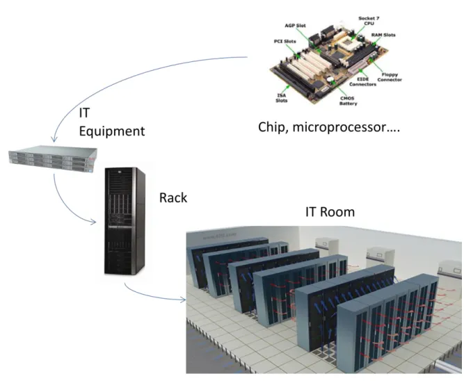
2.1 OverviewIT operations are a crucial aspect for most organizational procedures. One of the main concerns is business continuity; companies rely on their information systems to run their operations. If a system becomes unavailable, company operations may be impaired or stopped completely. A Data Center houses the electronic devices responsible to run IT operations (called IT equipment).This equipment is placed in cabinets known as racks. These racks are orderly
distributed in a room (IT Room), called sometimes white space [2], that refers to the usable raised floor area in square meters or footage.
Figure 1: Heat dissipation process in the Data Center. Source: IREC
Servers and related IT equipment generate a considerable amount of heat in a small area during their operation. Furthermore, the IT equipment is highly sensitive to temperature and humidity fluctuations, so a data center must keep restricted power and cooling conditions for assuring the integrity and functionality of its hosted equipment.
State of the art: Energy Efficiency in the Data Center 8 A Data Center must provide a reliable infrastructure for IT operations, in order to minimize any chance of disruption.
There are four American institutions that have developed Data Center Standards to design and support the required conditions:
TIA (Telecommunications Industry Association): TIA-942 Standard
The Uptime Institute : Data Center Site Infrastructure Tier Standard: Topology
ASHRAE (American Society of Heating, Refrigerating and Air-Conditioning Engineers):Data Center Design and Operation Series
NFPA (National Fire Protection Association): NFPA 75 :Standard for the Protection of Electronic Computer/Data Processing Equipment
The TIA- 942 Standard specifies the minimum requirements for telecommunications infrastructure applicable to any size data center. [2]
For the operational parameters and the HVAC facilities and requirements, the ASHRAE has published Data Center Design and Operation series, [3-10].
Referred to the reliability and liability requirements, the Uptime institute gives a Data Center classification[11].
To global understand the data center, in next sections are described the general aspects of DC infrastructure, topology and requirements, relating to the reference standards.
2.2 DC Structure
The first institution that begun to develop the computer room structure was the
Telecommunications Industry Association, as the IT equipment is mainly developed by the
Information and technology (IT) industry. Consequently, the main aspects given by the TIA are the related to the cabling system and equipment distribution referred to the communications needs. The standard will enable the DC design to be considered early in the building. The data center requires spaces dedicated to supporting the telecommunications infrastructure.
Telecommunications spaces shall be dedicated to support telecommunications cabling and equipment. Typical spaces found within a computer or IT room generally include the entrance room, main distribution area (MDA), horizontal distribution area (HDA), zone distribution area (ZDA) and equipment distribution area (EDA). Depending upon the size of the data center, not all of these spaces may be used within the structure. These spaces should be planned to provide for growth and transition to evolving technologies. These spaces may or may not be walled off or otherwise separated from the other computer room spaces.
Next table summarizes the DC Space Structure and distribution given by the TIA into three main categories:
Computer or IT Room/s Telecommunications Room
State of the art: Energy Efficiency in the Data Center 9
Data Center Support Areas
Figure 2: Data Center Space Structure. Source TIA 942
This space description gives the key to understand the Data Center equipment distribution. TIA 942 Data Center Space Structure
D ATA CE N TE R Computer/ IT Room Cabling and Networking
Main distribution area (MDA) Horizontal distribution area (HDA) Zone distribution area (ZDA)
Equipment distribution areas Servers, Storage… Racks and Cabinets
"Hot" and "cold" aisles Equipment placement
Placement relative to floor tile grid Access floor tile cuts
Installation of racks on access floors
Specifications Clearances
Ventilation Rack height , depth and width Rack and cabinet finishes Telecomu-nications Room Data center support areas UPS, Cooling, Switch boards Generator…
State of the art: Energy Efficiency in the Data Center
10
It room layout may consider two main spaces, the cabling and networking area and the IT equipment area.
By other side, the Data Centre infrastructure must include the additional space and equipment required to support data center operations , including power transformers, uninterruptible power supply (UPS), generators, computer room air conditioners (CRACs), chillers, air distribution systems, etc.
In next figure is shown the distribution proposed by the TIA in the data center.
State of the art: Energy Efficiency in the Data Center
11
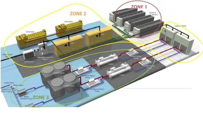
By other hand, The Green Grid has recently described another space division based on the physical infrastructure main areas[12].
All power and cooling physical infrastructure is located in at least one of these three zones. The zones are categorized as follows and are shown in next figure:
ZONE 1: inside the building and inside the physical data center (IT Room) IT equipment
Power distribution units
ZONE 2: inside the building but outside of the IT Room UPS, Generator
CRACs
ZONE 3: outside of the building:
Chillers, Cooling Tower…
Storage tank
Figure 4: Example of zones categorization in the DC. Source : TIA 942
State of the art: Energy Efficiency in the Data Center
12
2.3 DC Requirements
The IT room is an environmentally controlled space that houses equipment and cabling directly related to the computer and other telecommunications systems.
The TIA-942 focuses on the data center cabling system infrastructure, redundancy and design and outlines the other room requirements, referencing to other specific standards.
Other organizations establish the requirements for environmental conditions (ASHRAE) and fire protection in computer rooms (NFPA 75).
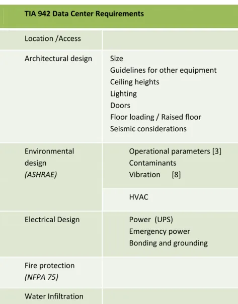
The TIA-942 standard groups the IT or Computer Room requirements into five broad categories: Location /Access
Architectural design Environmental Design Electrical Design Fire Protection Water Infiltration
Figure 5: Data Center Requirements. Source: TIA 942
TIA 942 Data Center Requirements Location /Access
Architectural design Size
Guidelines for other equipment Ceiling heights
Lighting Doors
Floor loading / Raised floor Seismic considerations Environmental
design (ASHRAE)
Operational parameters [3] Contaminants Vibration [8] HVAC
Electrical Design Power (UPS) Emergency power Bonding and grounding Fire protection
(NFPA 75)
State of the art: Energy Efficiency in the Data Center
13
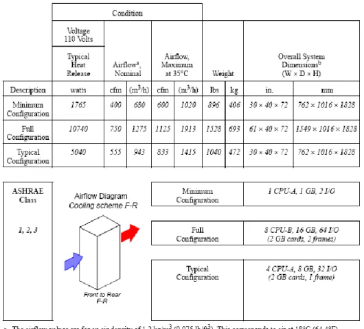
To understand the room requirements, the first step is to check what are the IT equipment specific conditions given by each manufacturer in the product datasheet:
Figure 6: Sun Oracle Storage Server Physical specifications. Source: Sun Microsystems
In the product datasheet appears the equipment specifications classified in four main groups: Equipment Dimension
Environment (Temperature, Cooling and Airflow) Power
Emissions
The equipment dimension and quantity is necessary to select the kind of rack to house it, and to check the IT room area and floor resistance required for the rack.
Room environment condition is understood as the air temperature and relative humidity necessary for the correct operation of the equipment. By other hand, the datasheet usually gives the
equipment heat dissipation in BTU/h (British Thermal Unit = 0.293 W.h) and the airflow needed to compensate the heat generated in CFM (cubic foot meters).
State of the art: Energy Efficiency in the Data Center
14
A general rule to know the amount of heat dissipation per equipment is that for every watt of power consumed, a thermal watt of heat is generated.
The ASHRAE provides environmental conditions for electronic equipment and for facility operation in the Thermal Guidelines for Data Processing Environments[3] .
Four environmental classes are described:
Class 1: Typically a data center with tightly controlled environmental parameters (dew point, temperature, and relative humidity) and mission critical operations; types of products typically designed for this environment are enterprise servers and storage products.
Class 2: Typically an information technology space or office or lab environment with some control of environmental parameters (dew point, temperature, and relative humidity); types of products typically designed for this environment are small servers, storage products, personal computers, and workstations.
Class 3: Typically an office, home, or transportable environment with little control of environmental parameters (temperature only); types of products typically designed for this environment are personal computers, workstations, laptops, and printers.
Class 4: Typically a point-of-sale or light industrial or factory environment with weather protection, sufficient winter heating, and ventilation; types of products typically designed for this environment
The IT equipment housed on the DC generally corresponds to classes 1 and 2.
The next table is delineated for both equipment operation and equipment power off.
The equipment operating environmental conditions, including allowable and recommended values, refer to the state of the air entering the electronic equipment (Inlet Conditions). The conditions for Classes 1 through 4 are the result of consensus among the many environmental specifications of manufacturers of IT equipment.
State of the art: Energy Efficiency in the Data Center
15
The datasheet must give the airflow protocol of the equipment. Depending on this aspect, the inlet surface (cold air entering to the equipment) and the outlet surface (exit surface for the heat generated) can vary, as is shown in next picture. The airflow configuration determines the cooling design and operation inside the room and the layout of the IT equipment.
Figure 8: Airflow Patterns. Source: ASHRAE
Another example of cooling requirements datasheet is the model proposed by the ASHRAE in [3].
State of the art: Energy Efficiency in the Data Center
16
The IT equipment uses power to run, and this amount of power demand is needed during the implementation of the electrical system.
The equipment manufacturer (IBM, HP, Sun, Dell….) gives always the peak value for the power consumption and the heat dissipation, so the cooling and electric facilities must be designed considering these peaks. Usually these values correspond to 1 or 2 U (unit) of equipment.
For example, a conventional rack can hold up to 42 U, so, for a server (1 U) of 1kW of power use, this rack at full capacity can demand 42 kW of power and 42 kWt of cooling.
In addition, other important parameter provided in the datasheet is the Electromagnetic Interference (EMI) on the communication network. EMI is the interference emitted from an electrical device that has an adverse effect on the function of a surrounding or connected device. In the data center there is a significant quantity of electronic devices requiring power as well as communication. The adverse effects of EMI on data communication can be mitigated in the data center by following industry accepted standards and by using best practices for grounding, cable routing and separation.
The Federal Communications Commission (FCC) of America defines acceptable limits for radiated and conducted emissions. To ensure EMC between devices, only FCC Class-A compliant devices should be deployed in the data center.
The IT room should meet the NFPA 75 (Standard for the Protection of Electronic Computer/Data Processing Equipment), this standard outlines requirements for computer installations needing fire protection and special building construction, rooms, areas, or operating environments[13].
The floor layout should be consistent with equipment and facility providers requirements, examples are listed below:
– Floor loading requirements including equipment, cables, patch cords, and media (static concentrated load, static uniform floor load, dynamic rolling load).
– Service clearance requirements (clearance requirements on each side of the equipment required for adequate servicing of the equipment).
– Air flow requirements. – Mounting requirements.
– DC power requirements and circuit length restrictions.
– Equipment connectivity length requirements (for example, maximum channel lengths to peripherals and consoles).
State of the art: Energy Efficiency in the Data Center
17
2.4 DC Design Process
The steps in the design process described below apply to the design of a new data center or the expansion of an existing data center. It is essential for either case that the design of the
telecommunications cabling system, equipment floor plan, electrical plans, architectural plan, HVAC, security, and lighting systems be coordinated. Ideally, the process should be:
a) Estimate IT equipment space, power, and cooling requirements of the data center at full capacity. Anticipate future IT equipment power and cooling trends (DC expected grow) over the lifetime of the data center.
b) Provide space, power, cooling, security, floor loading, grounding, electrical protection, and other facility requirements to architects and engineers. Provide requirements for operations center, loading dock, storage room, staging areas and other support areas. c) Coordinate preliminary data center space plans from architect and engineers. Suggest
changes as required.
d) Create an equipment floor plan including placement of major rooms and spaces for entrance rooms, main distribution areas, horizontal distribution areas, zone distribution areas and equipment distribution areas. Provide expected power, cooling, and floor loading requirements for equipment to engineers. Provide requirements for
telecommunications pathways.
e) Obtain an updated plan from engineers with telecommunications pathways, electrical equipment, and mechanical equipment added to the data center floor plan at full capacity.
f) Design telecommunications cabling system based on the needs of the equipment to be located in the data center.
2.5 DC Classification
A DC is a facility that works every 24 hours the 365 days of the year. As is known, the critical operations of a company are running on it, so the electrical and in general system failure is the key for design considerations.
Reliability and continuous operation are main aspects to be considered during the DC design, these aspects are accomplished trough redundancy.
Is understood as redundancy the system feature of having reserves of components to provide support in case one component fails to ensure the service continuity that the system performs. N is the number of elements to satisfy the operation normal conditions. Redundancy is often compared to the baseline of N, and N + 1, N + 2, 2N and 2(N + 1) examples of redundancy levels. Depending on the level s of availability and redundancy of the data center facility infrastructure, the Uptime Institute defines four tier ratings.
The Uptime Institute has published the Data Center Site Infrastructure Tier Standard[11]. This standard describes criteria to differentiate four classifications of site infrastructure topology based on increasing levels of redundant capacity components and distribution paths. This standard focus on definitions of the four Tiers and the performance confirmation tests for determining compliance to the definitions.
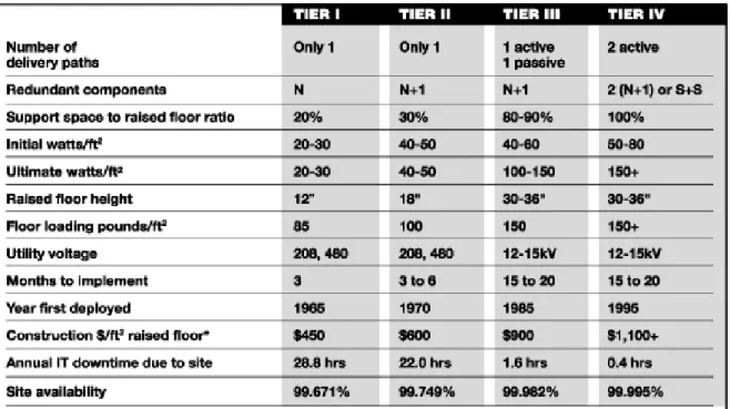
The next figure summarizes the main aspects of the Tier Standard. The design and redundancy improvements obtain a higher site availability.
State of the art: Energy Efficiency in the Data Center
18
Availability is a percentage value representing the degree to which a system or component is operational and accessible when required for use.
Availability is composed of two variables, mean time between failure (MTBF) and mean time to repair (MTTR).
MTBF is a basic measure of a system’s reliability. Typically, it means the loss of critical processing equipment. Mean time to repair (MTTR) is the expected time to recover a system from a failure and is equally important because the time to recover could be much greater than the time for service personnel to respond. Together, these two factors attempt to quantify the expected availability of a critical system or, in other words, its expected uptime.
The formula below illustrates how both MTBF and MTTR impact the overall availability of a system. As the MTBF goes up, availability goes up. As the MTTR goes up, availability goes down.
Availability= MTBF/ (MTBF+ MTTR) Figure 10: Uptime Institute Availability Calculation
Figure 11: Scheme of Tier Level Infrastructure Requirements. Source: Uptime Institute
In next sections is explained the main aspects of each Tier level. 2.4.1 Tier I: Basic Site Infrastructure
State of the art: Energy Efficiency in the Data Center
19
a) A Tier I basic data center has redundant capacity components and a single, non-redundant distribution path serving the computer equipment.
The performance confirmation tests:
a) There is sufficient capacity to meet the needs of the site.
b) Planned work will require most or all of the site infrastructure systems to be shut down affecting computer equipment, systems, and end users.
The operational impacts:
a) The site is susceptible to disruption from both planned and unplanned activities. Operation (Human) errors of site infrastructure components will cause a data center disruption.
b) An unplanned outage or failure of any capacity system, capacity component, or distribution element will impact the computer equipment.
c) The site infrastructure must be completely shut down on an annual basis to safely perform necessary preventive maintenance and repair work. Urgent situations may require more frequent shutdowns. Failure to regularly perform maintenance significantly increases the risk of unplanned disruption as well as the severity of the consequential failure.
2.4.2 Tier II: Redundant Site Infrastructure Capacity Components The fundamental requirement:
a) A Tier II data center has redundant capacity components and a single, non-redundant distribution path serving the computer equipment.
The performance confirmation tests:
a) Redundant capacity components can be removed from service on a planned basis without causing any of the computer equipment to be shut down.
b) Removing distribution paths from service for maintenance or other activity requires shutdown of computer equipment.
State of the art: Energy Efficiency in the Data Center
20
a) The site is susceptible to disruption from both planned activities and unplanned events. Operation (Human) errors of site infrastructure components may cause a data center disruption.
b) An unplanned capacity component failure may impact the computer equipment. An unplanned outage or failure of any capacity system or distribution element will impact the computer equipment.
c) The site infrastructure must be completely shut down on an annual basis to safely perform preventive maintenance and repair work. Urgent situations may require more frequent shutdowns. Failure to regularly perform maintenance significantly increases the risk of unplanned disruption as well as the severity of the consequential failure.
2.4.3 Tier III: Concurrently Maintainable Site Infrastructure The fundamental requirements:
a) A Concurrently Maintainable data center has redundant capacity components and multiple independent distribution paths serving the computer equipment. Only one distribution path is required to serve the computer equipment at any time.
b) All IT equipment is dual powered and installed properly to be compatible with the topology of the site’s architecture. Transfer devices, such as point-of-use switches, must be incorporated for computer equipment that does not meet this specification.
The performance confirmation tests:
a) Each and every capacity component and element in the distribution paths can be removed from service on a planned basis without impacting any of the computer equipment.
b) There is sufficient permanently installed capacity to meet the needs of the site when redundant components are removed from service for any reason.
The operational impacts:
a) The site is susceptible to disruption from unplanned activities. Operation errors of site infrastructure components may cause a computer disruption.
b) An unplanned outage or failure of any capacity system will impact the computer equipment.
c) An unplanned outage or failure of a capacity component or distribution element may impact the computer equipment.
State of the art: Energy Efficiency in the Data Center
21
d) Planned site infrastructure maintenance can be performed by using the redundant capacity components and distribution paths to safely work on the remaining equipment. e) During maintenance activities, the risk of disruption may be elevated.
2.4.4 Tier IV: Fault Tolerant Site Infrastructure The fundamental requirements:
a) A Fault Tolerant data center has multiple, independent, physically isolated systems that provide redundant capacity components and multiple, independent, diverse, active distribution paths simultaneously serving the computer equipment. The redundant capacity components and diverse distribution paths shall be configured such that “N” capacity is providing power and cooling to the computer equipment after any infrastructure failure. b) All IT equipment is dual powered and installed properly to be compatible with the topology of the site’s architecture. Transfer devices, such as point-of-use switches, must be incorporated for computer equipment that does not meet this specification.
c) Complementary systems and distribution paths must be physically isolated from one another (compartmentalized) to prevent any single event from simultaneously impacting both systems or distribution paths.
d) Continuous Cooling is required. The performance confirmation tests:
a) A single failure of any capacity system, capacity component, or distribution element will not impact the computer equipment.
b) The system itself automatically responds to a failure to prevent further impact to the site.
c) Each and every capacity component and element in the distribution paths can be removed from service on a planned basis without impacting any of the computer equipment.
d) There is sufficient capacity to meet the needs of the site when redundant components or distribution paths are removed from service for any reason.
The operational impacts:
State of the art: Energy Efficiency in the Data Center
22
b) The site is not susceptible to disruption from any planned work activities.
c) The site infrastructure maintenance can be performed by using the redundant capacity components and distribution paths to safely work on the remaining equipment.
d) During maintenance activity where redundant capacity components or a distribution path shut down, the computer equipment is exposed to an increased risk of disruption in the event a failure occurs on the remaining path. This maintenance configuration does not defeat the Tier rating achieved in normal operations.
e) Operation of the fire alarm, fire suppression, or the emergency power off (EPO) feature may cause a data center disruption.
A summary of the preceding requirements defining the four distinct Tier classification levels is in next table.
State of the art: Energy Efficiency in the Data Center
23
3.
Data Center Energy consumption.
A data centre uses 10 to 100 times more energy per square meter than a typical office building [14].In fact,European Data Center electric consumption in 2007 was 56 TWh and the estimation for 2020 rises to 104 TWh. More precisely in Spain, a data center built on 2010 can demand 40 times the electricity that an office building.
Data Center consumption is partially due to the density of equipment on it (Data centers are not designed for humans but for computers, and as a result typically have minimal circulation of fresh air and no windows), and to the fact that the data centre runs continuously.
The Data Center electric consumption belongs mainly to two groups of load:
IT Load: this relates to the consumption of the IT equipment in the data center; and can be described as the IT work capacity employed for a given IT power consumption. It is also important to consider the use of that capacity as part of efficiency in the data centre. Facilities Load : this relates to the mechanical and electrical systems that support the IT
electrical load such as cooling systems (chiller plant, fans, pumps) air conditioning units, UPS, PDU’s etc..
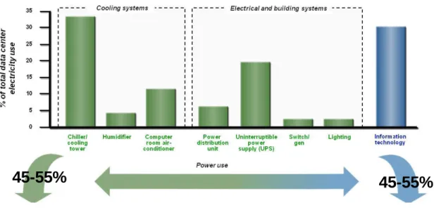
Figure 13: Data Center electrical consumption breakdown. Source: IBM
In figure 12 appears the general data center electric consumption demand in Europe. The green color represents the facilities load contribution and the blue one, the It load contribution. The power consumption that belongs to the IT equipment usually represents the 45-55% of the total in today data centers, approximately the same power needed by the infrastructure to cover the IT equipment requirements.
State of the art: Energy Efficiency in the Data Center
24
Figure 14: Data Centre average Power allocation. Source: ASHRAE
Figure 15: Historical data center energy consumption with future energy use projections. Source: EPA
The facilities load can be breakdown in two principal groups: the Cooling System and the Electrical & building Systems.
State of the art: Energy Efficiency in the Data Center
25
As shown in previous pictures, the principal energy use belongs to IT Equipment’s consumption. The energy efficiency on Electronics and IT Equipment is out of the scope of this document. This task belongs to the HW manufacturers, developers and end users.
The second main group of consumption in a data center is the Cooling System.
To better understand the breakdown of data center power use, the first aspect to analyze is the IT Load and its nature depending on the short of equipment that constitutes it. The IT equipment requirements will determine the power of the infrastructure needed, and in a way, the facilities load (whenever the facilities design is well done). (See section 4.1.1)
When a Data Center is designed, the first data needed is the short of IT equipment that will be housed in the data centre and its power demand.
Estimating power use of IT equipment isn’t easy. The power use of electronic equipment varies with hardware configuration and class, usage, and environmental conditions. The power supplies for these devices are sized for the maximum loads expected when the server is fully configured, so the actual measured loads observed in typical installations are much lower than the rated power of the power supply.[15]
IT equipment technology is advancing at a rapid pace, resulting in relatively short product cycles and an increased frequency of equipment upgrades. Since IT facilities that house this equipment, along with their associated infrastructure, are composed of facilities that are typically conceived to have longer life cycles, any modern IT facility design needs the ability to continuously accommodate the multiple IT equipment deployments that will experience during its lifetime.
Based on the latest information from all the leading IT equipment manufacturers, the ASHRAE has published the Datacom Power Trends and Cooling Applications [4],that provides new and
expanded IT equipment power trend charts to allow the DC facilities designer to more accurately predict the IT equipment loads that the facility can expect to house in the future, as well as provide ways of applying the trend information to DC facility designs today.
Next figure shows the trend for the heat load per IT equipment and per year. As explained in previous section, the heat dissipation in the It equipment is directly proportional to the electrical consumption. This chart helps in the DC power estimation for future needs of the facility.
State of the art: Energy Efficiency in the Data Center
26
Figure 16: DataCom Power Trends. Source: ASHRAE
When considering the whole facility or even just a IT room within the facility, semiconductors and chips seem like a tiny element and of little importance or relevance. However, semiconductors and chips have a major impact on the load of an IT facility and are a critical source for predicting the loads, especially future loads.
Since the chips are the primary component used in the IT equipment, the chip trends can be considered an early indicator to future trends in that equipment.
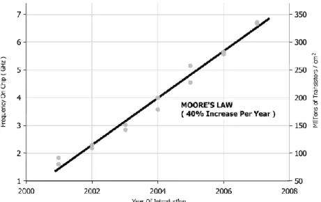
The power trend of this chart has been created with the information trends at the chip level given by Moore’s Law.
State of the art: Energy Efficiency in the Data Center
27
Moore's law describes a long-term trend in the history of computing hardware. The number of transistors that can be placed inexpensively on an integrated circuit has doubled approximately every 18 months. The trend has continued for more than half a century and is not expected to stop until 2015 or later. Consequently, the increase of the transistors causes the frequency rising on chip, what increases the heat dissipation.
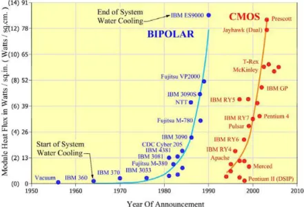
Figure 18: Heat Dissipation in Transistors. Source: ASHRAE
The processor is the primary source of heat generation within a piece of electronic
equipment with surface temperatures rising to greater than 100 ºC .The processor typically has some means of integral cooling to transport the heat away from the chip surface. The air is channeled within the server to transport the heat that is generated by the server components through convection before the server fans exhaust the warmer air back out to the surrounding environment.
The provisioning is a main aspect to take into account while the DC is being designed. The provisioning refers to planning and allocating resources (financial, spatial, etc.) to accommodate changes that may be required in the future. Provisioning could result in spatial considerations, such as providing additional floor area to accommodate the delivery and installation of additional equipment, or provisioning could have a more direct impact on the current design, such as oversizing distribution infrastructure (e.g., pipe sizes, ductwork, etc.) to be able to handle future capacity.
As the IT equipment power needs is growing to have more processing capacity, the new challenge for hardware manufacturers (IBM, HP, Dell, Sun…) is to deploy new systems that has more process capacity with the same power demand. This is the key to deploy the “Sustainable Data Center”. In the other way, the challenge for engineers is to build the facility the more sustainable as possible, and for this, it is necessary give to the IT equipment exactly what is demanding, that is producing basically the electricity and cooling needed, the more efficiently and reliable as we can.
State of the art: Energy Efficiency in the Data Center
28
That is why the energy monitoring systems are crucial to be implemented on the data center facility. The consumption of the IT equipment varies with the operations supported by it, so depending on the use, two data center with the same equipment and infrastructure can present different electric and thermal loads and consumptions.
The Best Practice Scenario is the first to show a drop in data center energy consumption in 2011 compared to 2006 levels. This scenario includes energy-saving measures such as moderate
consolidation of data centers, aggressive adoption of energy-efficient servers, and use of improved fans, chillers, and free cooling. The result reaches just under 40 billion kilowatt hours of energy consumption.
The State of the Art Scenario demonstrates the most drastic data center energy consumption reduction. The scenario includes all changes within the Best Practice Scenario and adds power management applications, liquid cooling, and combined heat and power. The result reaches just over 30 .109 kilowatt hours of energy consumption.[16]
Many data centers owners and designers are simply not aware of the financial, environmental and infrastructure benefits to be gained from improving the energy efficiency of their facilities. Due to this fact, on December 2006,President George W. Bush signed a bill that required the U.S. EPA (Environmental Protection Agency), to study the growth and energy consumption of data centers with the intention to determine best practices for not only data centre energy efficiency, but also for cost efficiency [17].Since that time, the Lawrence Berkeley National Laboratory has developed a list of 67 best practices for optimal data centre design [18]. They are broken up into the following categories: Mechanical, IT equipment, Electrical Infrastructure, Lighting, and Commissioning and Retro-commissioning[19].
By other hand, on November 2009, the European Union has published the Code of Conduct on Data Centers Energy Efficiency[20] , in response to increasing energy consumption in data centers and the need to reduce the related environmental, economic and energy supply security impacts . This Code of Conduct proposes general principles and practical actions to be followed by all parties involved in data centers, operating in the EU, to result in more efficient and economic use of energy, without jeopardising the reliability and operational continuity of the services provided by data centers.
A typical rack of new servers draws approximately 5-45 kilowatts of power alone, and a data centre houses hundreds of these racks [21].Running all day every day, one 20 kilowatt rack alone uses over 170000 kWh annually. That’s over twenty five times the amount of energy in average that a
European resident uses in a year[22].
According to the EPA a 10% of energy savings by all US data centers would save 10,7 109 kWh annually, enough energy to power one million US households [14].
State of the art: Energy Efficiency in the Data Center
29
4.
Data Center Energy Efficient Facilities
4.1 DC Facilities OverviewThe IT equipment requirements give the key for the dimensioning of the data center facilities.
As mentioned in section 2, the IT equipment main requirements to operate correctly are: Power to run.
Cold air to remove the heat generated by the equipment during its operation. Safe and Secure environment
Continuous operation: 24 hours x 7 days/week Data and communication supply
This requirements are achieved through these facilities: Power: Electrical System
Cold air : Cooling System
Safe and secure environment: Fire Protection System, Water Detection System, Access Control….
Continuous Operation: Uninterruptible Power Supply, Emergency Generation System, Equipment redundancy…
Cabling and Networking System
Other main aspect of the data center infrastructure is the architectural requirements, which implies special considerations: the raised floor, walls, doors, technical areas…
The intent of the present document is the understanding of the IT Infrastructure
requirements from the point of view of energy efficiency in the physical infrastructure, not on the IT equipment.
In section 3 is described the data center power consumption breakdown. As is shown, the physical infrastructure main groups of power demand are the electrical and cooling facilities.
The cabling and networking systems are out of the document scope. These systems are explained in detail in the TIA-942[2].
The main objective then, is the description of the requirements and the facilities to
optimize the energy consumption. As a consequence, the safety and security facilities, such as access control, fire protection and water detection are just mentioned and referenced. In resume, the data center facilities scope of this section are:
Cooling System Electrical System
State of the art: Energy Efficiency in the Data Center
30
4.2 Mechanical. HVAC
One of the most important part of the data center infrastructure are the HVAC facilities. Next figure illustrates an example of a data center cooling system.
Figure 19: Example of a conventional cooling system for a Data Center: Source: IREC
The cooling system can be divided in three main parts located in different places of the building: Cold Water Production and distribution situated outside the data center in Zone 3 (Building
Roof) [12].
Cold air production situated in Zone 2 (technical room outside the IT Room) or in zone 1 (IT Room)[12].
The air distribution and delivery to heat load is situated in Zone 1 (IT Room)[12].
The efficiency and effectiveness of a datacenter cooling system is heavily influenced by the path, temperature and quantity of cooling air delivered to the IT equipment and waste hot air removed from the equipment.
From the point of view of energy efficiency in the facility, where is possible to can earn more energy, because of the complexity of the load, is in the cooling system (see section 3). Depending on the data center location and density load there are multiples open challenges to deploy new concepts for cooling the IT equipment.
Water Distribution
Air Distribution
Cold Water
Production
Cold Air
Production
Heat Load
Piping, Pumps, Collectors Chiller Plant, Cooling Tower or Dry Cooler..Computer Room Air Conditioning Unit
(CRAC)
Raised Floor Plenum/ Perforated Tiles/ Room
State of the art: Energy Efficiency in the Data Center
31
4.1.1. HVAC Load Considerations
A data center houses different classes of equipment. Each short of equipment has a range of power consumption and as a consequence, a different amount of heat dissipation. This aspect justify why a data center usually represents a heterogeneous heat load environment.
The figure 18 has been done basing on the ASHRAE power trend chart (figure 15) and with a reference rack footprint of 0,65 m2.The chart shows the heat dissipation by short of IT equipment:
State of the art: Energy Efficiency in the Data Center
32
Depending on the amount of heat dissipated per rack, there is a classification in terms of heat density:
1. Normal Density: < 20 kW/rack
2. High density : >20 kW/rack- <35 kW/rack 3. Extreme density >35 kW/rack .
Each kind of equipment presents a “heat load”. The addition of the heat load of all the racks housed in the IT room, gives the cooling demand of the room.
The division of this value and IT Room floor area is the heat density (W/m2).
∑ ̇
̇
Figure 21: Total dissipation in IT Room. Source: IREC
̇
Figure 22: IT Rooms Heat density. Source: IREC
Where:
̇ [W] is the heat dissipated per IT equipment
[m2] IT Room Area
̇ [W] IT Room Cooling demand
The short of equipment housed in the IT Room, then, will determine the size of the infrastructure needed. For example a computer room, usually, has higher power and cooling requirements than a Bank data center , due to the nature of the IT equipment, consisting basically in Compute blade servers and high density communication hardware (high and extreme density equipment).
By other side, a Bank data center will have stronger requirements in terms of reliability with higher tier levels in design and operation (see Section 2).
State of the art: Energy Efficiency in the Data Center
33
4.1.2. Airflow Management
The thermal environment of data centers plays a significant role in affecting the energy efficiency and the reliability of data center operation.
As is known, it is necessary to remove the heat dissipated by the IT equipment during its operation. The heat removed in a rack by the airflow is represented in this expression [5]:
̇ ̇ Figure 23: IT equipment heat dissipation removal
Where:
̇ [kW] is the heat to be removed by the cooling system air. [kg/m3] Air density (constant).
̇ [m3/s] Cold airflow through the rack.
[kW/kg.K] is the air specific heat at constant pressure (constant).
[K] is the medium Delta T that the air reaches going through the rack.
For a constant heat removed or dissipated there are two parameters that can vary, the airflow and the delta T.
First data center cooling system consisted in the impulsion of cold air directly to IT Room ambient. This way of cooling presents airflow inefficiencies around the equipment that forces the impulsion of more air than necessary .The next improvement needed is to manage the airflow efficiently to achieve the next objectives:
Eliminate mixing and recirculation around the IT equipment.
Maximize return air temperature by supplying air directly to the loads. Cooling air should be supplied directly to the IT equipment air intake location.
The achievement of these aspects begins through the installation of Computer Room Air
Conditioning units (CRAC) with impulsion to under floor plenum. A perforated tile is placed near the rack, so the impulsion that way is nearest that in the previous configuration. The under floor plenum function not was only for cabling and electric lines allocation, but started to be a plenum to homogenize the air’s pressure from the CRACs to the point of impulsion.
State of the art: Energy Efficiency in the Data Center
34
Figure 24: IT Room cooling system principles. ASHRAE
Assuming this way of cooling the IT equipment as the basis of the IT Room cooling system, there are several strategies to improve the air management and ultimately the energy efficiency of the system [5],[18],[19] :
Hot Aisle/Cold Aisle configuration: Arranging the IT equipment with this layout, the cold air flows through the perforated tiles placed in the cold corridor in front of each rack and gets into it. The heat removed from each rack comes out by its rear door and returns to the cooling system flowing through the hot corridor until it arrives to the CRAC units.
Figure 25: Hot/Cold Aisle layout. Source: Rittal
Flexible strip curtains: Use flexible strip curtains to improve the separation by blocking open space above the racks.
Figure 26: Flexible Strip Curtains on cold aisle. Source: Rittal
Blank unused rack positions. Standard IT equipment racks exhaust hot air out the back and draw cooling air in the front. Openings that form holes through the rack should be blocked in some manner to prevent hot air from being pulled forward and recirculated back into the IT equipment.
State of the art: Energy Efficiency in the Data Center
35
Figure 27: Blanking panels of different dimensions. Source: Rittal
Figure 28: Blanking Panels benefits Source: Rittal
Design for IT airflow configuration. Some IT equipment does not have a front-to-back cooling airflow configuration. Configure racks to ensure that equipment with side-to-side, top-discharge, or other airflow configurations reject heat away from other equipment air intakes.
Use appropriate diffusers: Diffusers should be selected that deliver air directly to the IT equipment, without regard for drafts or throw concerns that dominate the design of most office-based diffusers, there are several solutions for it and the most popular is to use perforated tiles.
State of the art: Energy Efficiency in the Data Center
36
Position supply and returns to minimize mixing and short circuiting. Diffusers should be located to deliver air directly to the IT equipment. At a minimum, diffusers should not be placed such that they direct air at rack or equipment heat exhausts, but rather direct air only towards where IT equipment draws in cooling air. Supplies and floor tiles should be located only where there is load to prevent short circuiting of cooling air directly to the returns; in particular, do not place perforated floor supply tiles near computer room air conditioning units using the as a return air path.
Figure 30: Undesired effects caused by the air recirculation. Source: Rittal
Minimize air leaks in raised floor systems. In systems that utilize a raised floor as a supply plenum, minimize air leaks through cable accesses in hot aisles, where supply air is essentially wasted. Also implement through policy or design control of supply tile placement to ensure that supply tiles are not placed in areas without appropriate load and/or near the return of the cooling system, where cooling air would short-circuit and, again, be wasted.
Figure 31Air leaks in raised floor systems. Source:Rittal
When the CRAC units are placed inside the room, the optimal position is perpendicular with the hot aisles (to avoiding air short circuit due to CRAC proximity to first perforated tiles of each row). The reason for this is that as the impulsion is done by under floor to improve the
State of the art: Energy Efficiency in the Data Center
37
pressure and the airflow distribution, the return of hot air to CRAC units is facilitated if it is aligned with hot corridors, where the hot air flows from the racks to the ambient of IT room. (See Section 4.1.3).
Whenever it is possible, place the CRAC units in a room adjacent (called cooling or technical corridor) lined up to the common wall of the IT room. Depending on the IT Room sizes and density loads maybe is necessary to have two cooling corridors (See Section 4.1.3).
Provide adequately sized return plenum or ceiling height. Overhead return plenums need to be sized to allow for the large quantities of air flow that is required.
Provide adequately sized supply. Underfloor supply plenums need to be sized to allow for the large quantities of air flow that is required. Common obstructions such as piping, cabling trays, or electrical conduits need to be accounted for when calculating the plenum space required. Blockages can cause high pressure drops and uneven flow, resulting in hot spots in areas where cooling air is short circuiting to the return path.
Figure 32. Examples of cabling trays placed in under floor plenums. Source:IBM
With all these strategies, the airflow management inside the room is improved.
Last trends on data center cooling system designs, as the ASHRAE recommend [10], are settled in providing higher inlet temperatures to IT equipment to be more efficient.
Lots of data centers today presents air inlet temperatures around 14-15ºC. To be more energy efficient we can set up the inlet temperature to IT room from 18-27ºC [10, 23].
By other hand, while this new temperature range is being established, a dominant problem became to appear as the new IT equipment heat dissipation started to grow caused by its higher power demands.
Associated with this increase, is the recirculation of hot air from the rack outlets to their inlets, causing the appearance of hot spots and an uneven inlet temperature distribution. Next pictures show what occurs:
State of the art: Energy Efficiency in the Data Center
38
Figure 33: Hot air recirculation in racks. Source: IBM
Figure 34: Hot air recirculation. Source: 42U
The pictures show the consequences of the combination of two aspects:
1. The rising of the inlet temperature (18-27 ºC) increases the amount of heat recirculation, caused by the decreasing of the air density with temperature, making easier the air recirculation from the back of the rack to the front of it.
2. The CRAC system delivers the cold air with a maximum delta T of 10-12 K.( Section 4.1.3.1.4).
This limitation on delta T value forces to impulse more airflow to the room as the thermal load is higher (see Equation number 1). The increase of airflow necessary to compensate the thermal load causes disturbances on the under floor plenum air pressure, rising the air velocity through the tiles bypassing the server inlet sometimes
.(
In a study done by the Uptime Institute, 59% of the cold air was bypassing the server inlet.[24])The hot spots cause the inefficient cooling of the equipment situated on the rack’s upper positions, which can interrupt their operation due to the higher inlet temperatures. This last aspect justifies the data center manager efforts on the improvement of cooling techniques.
State of the art: Energy Efficiency in the Data Center
39
Use an appropriate pressure in under floor supply plenums. A pressure too high will result in both higher fan costs and greater leakage and short circuiting of cooling air. A pressure too low can result in hot spots at the area most distant from the cooling supply air point and result in poor efficiency 'fixes' such as a lowering of the supply air temperature or overcooling the full space just to address the hot spots.
Rigid enclosures: Build rigid enclosures to fully separate the heat rejected from the rear of IT equipment from the cold air intakes on the front. The basic scheme of effects achieved through containment is shown in next figure:
Figure 35: Consequences of air containment. Source: IREC
In this way there are several possibilities:
o Cold aisle enclosure: With this solution all the cold air that arrives to the corridor gets into the racks. The improvement of efficiency is given by taking advantage of the inlet airflow to the rack that has a temperature and flow more uniform than in previous configuration. By other hand, the enclosure stops physically the air recirculation from the racks back, so the appearance of hot spots is disabled.
Figure 36: Cold aisle enclosure
o Hot aisle containment: In this configuration the hot air gets enclosed and conducted to the CRAC units, so it is reached higher return air temperatures.Higher return temperatures allow for greater savings from economization and lower fan volume
State of the art: Energy Efficiency in the Data Center
40
requirements; the higher the Delta T between supply and return, the best reduction in fan power possible.
Figure 37: Hot aisle enclosure with air suction. Source: 42U
Figure 38: Exhaust containment chimney
The airflow management best practice scenario results on the implementation and developing of few cooling techniques depending on the rack thermal load (function of IT equipment application and HW configuration)[25]. (See section 4.1.8-4.1.6.1)
4.1.3. Air Handler Systems
It may be desirable for HVAC systems serving IT equipment facilities to be independent of other systems in the building, although cross-connection with other systems may be desirable for backup. Redundant air-handling equipment is frequently used, normally with automatic operation. A complete air-handling system should provide ventilation air, air filtration, cooling and
dehumidification, humidification, and heating. Data Center cooling systems should be independent of other systems and may be required all the year, depending on design.
IT rooms can be conditioned with a wide variety of systems, including packaged computer room air-conditioning (CRAC) units and central station air-handling systems. Air-handling and refrigeration equipment may be located either inside or outside IT rooms.
State of the art: Energy Efficiency in the Data Center
41
4.1.3.1 CRAC Units
Computer room air-conditioning (CRAC) units are the most popular cooling solution for IT Rooms.
Figure 39: Typical CRAC/CRAH Unit with Downflow -Top air suction: Source: ASHRAE
CRAC units are specifically designed for IT equipment room applications and should be built and tested in accordance with the requirements of the latest revision of ANSI/ASHRAE Standard 127, Method of Testing for Rating Computer and Data Processing Room Unitary Air-Conditioners[26]. CRAC units are available in several types of cooling system configurations, including chilled water, direct expansion air cooled, direct expansion water cooled, and direct expansion glycol cooled.
Direct Expansion CRAC Units:
The direct expansion (DX) units typically have multiple refrigerant compressors with separate refrigeration circuits, air filters, humidifiers, and integrated control systems with remote monitoring panels and interfaces. Reheat coils are an option. CRAC units may also be equipped with propylene glycol precooling coils and associated drycoolers to permit water-side economizer operation where weather conditions make this strategy economical [4].
Air-cooled direct expansion units extract heat from the room and transfer it to the outside air using air-cooled refrigerant heat exchangers (condensers).
Once installed, the room unit and external condenser form an autonomous sealed circuit.
The remote condensers used with DX CRAC units include precise electronic fan-speed condensing pressure control to ensure trouble-free operation of the unit throughout the year under a very wide range of external air temperatures.
CRAC units with chilled-water coils may also be fitted with DX coils connected to remote outdoor air-cooled condensing units for redundant cooling sources.
State of the art: Energy Efficiency in the Data Center
42
Figure 40: Air Cooled Direct Expansion Unit.Source: Uniflair
Chiller Water CRAH (Computer Room Air Handlers) Units.
CRAC units utilizing chilled water for cooling do not contain refrigeration equipment within their packaging and generally require less servicing, can be more efficient, provide smaller room temperature variations, and more readily support heat recovery strategies than the equivalent DX equipment.
Chiller Water CRAC units use the availability of chilled water to control room conditions. This version of CRAC has a relatively simple construction and outstanding reliability.
Careful sizing of the heat exchanger coils yields a high sensible-to-total cooling ratio under most operating conditions at the appropriate chilled water temperatures.
State of the art: Energy Efficiency in the Data Center
43
Figure 41: Chiller Water CRAH Unit. Source: Uniflair
Dual-Cool CRAC units :
When in the data center´s infrastructure location there is a chiller water source, but with a
configuration that doesn´t ensure the required level of security and continuous operation, this kind of CRAC is a good option. This kind of CRAC unit is fitted with two completely independent cooling circuits:
• Chilled water
• Air-cooled or water-cooled direct expansion
In this case function priority is given to the chilled water circuit, with the microprocessor control automatically starting direct expansion operation if the chilled water supply fails or if the water is not cold enough to dissipate the entire heat load.
Alternatively the unit controls can be set to prioritize direct expansion cooling, activating chilled water operation only in the event of a compressor malfunction.
These kind of CRAC units therefore provide a very high level of security; ensuring continuous system operation at all times and with the flexibility to manage the cooling resources in the best way for the particular installation.
State of the art: Energy Efficiency in the Data Center
44
Figure 42: Twin Coil CRAC Unit. Source: Uniflair
From the point of view of energy efficiency of cooling system the first step to take to improve the efficiency is to choose a water air based system for the data center and avoid as much as possible the direct expansion.[18] [19]
4.1.3.1.1 CRAC Location
Depending on the Data Center size and typology, CRAC units are placed inside the IT room or remotely located and ducted to the conditioned space (see figures below). Whether they are remote or not, their temperature and humidity sensors should be located to properly control the inlet air conditions to the IT equipment within specified tolerances. Analysis of airflow patterns within the IT equipment room with advanced techniques such as computational fluid dynamics (CFD) may be required to optimally locate the IT equipment, the CRAC units, and the corresponding temperature and humidity sensors. Otherwise, it may be possible that the sensors are in a location that is not conditioned by the CRAC unit they control or in a location that is not optimum and thereby forces the cooling system to expend more energy than required.
State of the art: Energy Efficiency in the Data Center
45
Figure 44: CRAC Unit Location in technical corridors beside the IT Room
4.1.3.1.2 Humidity Control
Types of available humidifiers within CRAC units may include steam, infrared, and ultrasonic. Thought should be given to maintenance and reliability of humidifiers.
It may be beneficial to relocate all humidification to a dedicated central system.
Another consideration is that certain humidification methods, or use of improperly treated makeup water, are more likely to carry fine particulates to the space.
Reheat is sometimes used in the dehumidification mode when the air is overcooled for the purpose of removing moisture. Sensible heat is introduced to supplement the actual load in the space typically by use of electric, hot water, or steam coils upon a call for reheat. Use of waste heat of compression (hot gas) for reheat may also be available as an energy-saving option. IT facilities should be enclosed with a vapor barrier for humidity control.
4.1.3.1.3 Ventilation
In systems using CRAC units, is necessary to introduce outside air through a dedicated system serving all areas. This dedicated system will often provide pressurization control and also control the humidity in the IT equipment room based on dew point, allowing the primary system serving the space to provide sensible-only cooling.
The IT Room ventilation consists in introduce between 1 and 2 air changes per hour 4.1.3.1.4 Overview of CRAC efficiency.
ASHRAE TC 9.9 committee recently published the 2008 ASHRAE Environmental Guidelines for Datacom Equipment [10]which extended the temperature-humidity envelope to provide greater flexibility in data center facility operations, particularly with the goal of reducing energy
consumption. The recommended temperature limits are from 18ºC to 27ºC. The humidity is limited to less than 60% with the lower and upper dew point temperatures of 5.5ºC and 15ºC.
State of the art: Energy Efficiency in the Data Center
46
These values are expressed in relation to temperatures in the cold aisle. Consequently, it must be considered only in case of room’s layout with hot and cold aisles. The CRAC and hardware
manufacturer’s suggestion is the system operation below 23°C .At this temperature, the server´s fans starts to rise their revolutions increasing their power consumption, and consequently the server´s one.
Figure 45: Variation of fan power requirements with server inlet temperature. Source: ASHRAE
By other hand, the temperature control in the chilled water units permits to set these values, so, it is possible to reach higher return temperatures. As an example, a today chiller water plant permits the operation with water temperatures of 12-18°C, so at air side is possible to reach a return temperature of 33°C to the CRAC unit (IT Room).
Relative humidity is still regulated on the return side and its set point. Generally the relative humidity considered with return temperature higher than 30°C is 30%. This last aspect must not be confused with the values given by the Ashrae.
In relation to DX units they don’t have the same benefit of efficiency that in CW CRAC Units through the temperatures increase, but efficiency in terms of EER can be estimated in nominal conditions around 15%. The manufacturers suggestion in the case of DX units is to remain below 35°C .
4.1.3.2 Central Station Air Handling Units (AHUs)
Some larger IT facilities use central station AHUs. Specifically, many telecommunications central offices, regardless of size, utilize central systems. There are advantages and disadvantages to the use of central station AHUs. Some aspects of central station AHUs, as they relate to IT facility applications, are contained in this section.
4.1.3.2.1 Coil Selection
There is a wide range of heating and cooling coil types that can be used for IT facilities and ideally any coil design/specification should include modulating control. In addition, for dehumidification purposes, cooling coils with close dew point control is very important. Cooling coil control valves should be designed to “fail open.” For more information on cooling coil design, a good reference is the ASHRAE -HVAC Systems and Equipment.