• Hundreds of titles available
– Books, eBooks, and online
resources from industry experts
• Free U.S. shipping
• eBooks in multiple formats
– Read on your computer,
tablet, mobile device, or e-reader
• Print & eBook Best Value Packs
• eBook Deal of the Week
– Save up to 60% on featured titles
• Newsletter and special offers – Be the first to
hear about new releases, specials, and more
• Register your book – Get additional benefits
microsoftpressstore.com
Visit us today at
Get the latest news from Microsoft Press sent to
your inbox.
• New and upcoming books
• Special offers
• Free eBooks
• How-to articles
Sign up today at MicrosoftPressStore.com/Newsletters
Hear about
Wait, there’s more...
Find more great content and resources in the
Microsoft Press Guided Tours app.
The Microsoft Press Guided Tours app provides
insightful tours by Microsoft Press authors of new and
evolving Microsoft technologies.
Download from
Windows Store
Download from
Windows Store
• Share text, code, illustrations, videos, and links with
peers and friends
• Create and manage highlights and notes
• View resources and download code samples
• Tag resources as favorites or to read later
• Watch explanatory videos
PUBLISHED BY Microsoft Press
A division of Microsoft Corporation One Microsoft Way
Redmond, Washington 98052-6399
Copyright © 2015 by Microsoft Corporation All rights reserved.
No part of the contents of this book may be reproduced or transmitted in any form or by any means without the written permission of the publisher.
Library of Congress Control Number: 2014959113 ISBN: 978-0-7356-9567-2
Printed and bound in the United States of America. First Printing
Microsoft Press books are available through booksellers and distributors worldwide. If you need support related to this book, email Microsoft Press Support at [email protected]. Please tell us what you think of this book at http://aka.ms/tellpress.
This book is provided “as-is” and expresses the author’s views and opinions. The views, opinions and information expressed in this book, including URL and other Internet website references, may change without notice.
Some examples depicted herein are provided for illustration only and are fictitious. No real association or connection is intended or should be inferred.
Microsoft and the trademarks listed at http://www.microsoft.com on the “Trademarks” webpage are trademarks of the Microsoft group of companies. All other marks are property of their respective owners.
Acquisitions Editor: Karen Szall Developmental Editor: Karen Szall Editorial Production: Megan Smith-Creed Copyeditor: Megan Smith-Creed
Contents iii
Contents
Introduction ixChapter 1 Design and planning
1
Choosing a configuration ... 1Recommended hardware... 1
Minimal hardware ... 3
Architecture ... 4
Management ... 6
Logical networking ... 11
Storage ... 14
Compute ... 21
Network virtualization ... 23
Chapter 2 Deploying the management cluster
35
Overview of the management cluster ... 35Virtual Machine Manager ... 37
Service provider vs. enterprise ... 38
Configuration walkthrough ... 38
Procedure 1: Rack and connect management cluster hosts ... 38
Procedure 2: Install Windows Server on MGMT01 and MGMT02 ... 39
Procedure 3: Configure TenantNetwork teams ... 40
Procedure 4: Enable the Hyper-V role on MGMT01 and MGMT02 ... 43
Procedure 5: Configure Hyper-V virtual switches ... 43
Procedure 6: Create folder structure for VMs and software ... 45
What do you think of this book? We want to hear from you!
Microsoft is interested in hearing your feedback so we can continually improve our books and learning resources for you. To participate in a brief online survey, please visit:
Procedure 7: Configure Hyper-V settings ... 46
Procedure 8: Create management VMs ... 47
Procedure 9: Configure Active Directory Domain Services on DC01... 49
Procedure 10: Join management hosts to the Contoso domain ... 50
Procedure 11: Configure DC02 as a secondary DC ... 51
Procedure 12: Configure remaining management VMs ... 52
Procedure 13: Install and configure WSUS on the WSUS VM ... 54
Procedure 14: Configure WSUS GPO and auto-approvals... 56
Procedure 15: Install Windows Deployment Services ... 57
Procedure 16: Create administrative service accounts ... 58
Procedure 17: Add data and log disks to SQL01 and SQL02 ... 59
Procedure 18: Add a second virtual network adapter to SQL01 and SQL02 ... 60
Procedure 19: Create the guest cluster within SQL01 and SQL02 ... 61
Procedure 20: Install SQL Server on SQL01 and SQL02... 63
Procedure 21: Enable AlwaysOn high availability for SQL01 and SQL02 ... 65
Procedure 22: Add a second virtual network adapter to VMM01 and VMM02 ... 65
Procedure 23: Create the guest cluster within VMM01 and VMM02 ... 66
Procedure 24: Create an Active Directory Domain Services container for distributed key management ... 68
Procedure 25: Install Virtual Machine Manager management server prerequisites ... 69
Procedure 26: Install Virtual Machine Manager management server ... 70
Procedure 27: Create an AlwaysOn Availability Group for VirtualManagerDB ... 72
Procedure 28: Finalize Virtual Machine Manager installation ... 73
Chapter 3 Configuring network infrastructure
75
Configuration walkthrough ... 75
Logical networks ... 76
Network sites ... 77
Procedure 1: Create a logical network and site for tenant traffic ... 78
Static IP address pools ... 80
Procedure 2: Create an IP address pool for the Tenant_LN logical network ... 81
Procedure 3: Create a second logical network and site for the datacenter network ... 83
Procedure 4: Create static IP address pools for the Datacenter_LN logical network ... 85
Logical switches ... 87
Procedure 5: Create an uplink port profile ... 90
Procedure 6: Create a virtual network adapter port profile ... 92
Procedure 7: Create a port classification ... 94
Procedure 8: Create the logical switch ... 94
Chapter 4 Configuring storage infrastructure
99
Scale-Out File Server... 100Configuration walkthrough ... 101
Procedure 1: Rack and connect SOFS nodes ... 102
Procedure 2: Configure Baseboard Management Controllers ... 103
Procedure 3: Rack and connect JBODs to SOFS nodes... 104
Procedure 4: Configure a BMC administrator in System Center Virtual Machine Manager ... 105
Procedure 5: Create a run-as account for SetupAdmin ... 105
Procedure 6: Obtain a virtual hard disk for server deployment ... 106
Procedure 7: Create a physical computer profile ... 107
Procedure 8: Add a PXE server to System Center Virtual Machine Manager ... 109
Procedure 9: Pre-provision Active Directory accounts ... 111
Procedure 10: Configure the WDS server with DHCP ... 112
Procedure 11: Discover and provision the SOFS with
System Center Virtual Machine Manager ... 114
Procedure 12: Check the cluster validation report ... 117
Procedure 13: Update software, drivers, and firmware ... 118
Procedure 14: Create storage classifications ... 120
Procedure 15: Create a storage pool ... 121
Procedure 16: Create a witness disk for FSCLUSTER ... 124
Procedure 17: Create the virtual disks and file shares ... 125
Procedure 18: Create a library virtual machine ... 127
Procedure 19: Configure the library VM as the System Center Virtual Machine Manager library ... 129
Chapter 5 Configuring compute infrastructure
131
Configuration walkthrough ... 134Procedure 1: Create host groups in System Center Virtual Machine Manager ... 134
Procedure 2: Import management hosts into System Center Virtual Machine Manager ... 135
Procedure 3: Remove library server from MGMT01 ... 136
Procedure 4: Construct a management cluster ... 136
Procedure 5: Check the cluster validation report ... 137
Procedure 6: Assign file share storage to MGMT01 and MGMT02 ... 138
Procedure 7: Configure a file share witness for MGMTCLUS, VMMCLUSTER, and SQLCLUSTER ... 138
Procedure 8: Assign the file share witness to MGMTCLUS, VMMCLUSTER, and SQLCLUSTER ... 140
Procedure 9: Migrate managemnet virtual machines to shared storage ... 141
Procedure 10: Enable Dynamic Optimization ... 142
Procedure 11: Create availability sets for related virtual machines ... 144
Procedure 12: Rack and connect Hyper-V compute nodes ... 146
Procedure 13: Configure BMCs ... 146
Procedure 14: Configuring a BMC administrator in System Center Virtual Machine Manager (optional) ... 147 vi Contents
Procedure 15: Create a physical computer profile ... 148
Procedure 16: Discover and provision the Hyper-V hosts with System Center Virtual Machine Manager ... 150
Procedure 17: Update drivers and firmware on Hyper-V hosts ... 153
Procedure 18: Construct the Hyper-V cluster ... 154
Procedure 19: Check the cluster validation report ... 155
Procedure 20: Assign file share storage to Hyper-V cluster ... 155
Procedure 21: Configure the file share witness for HVCLUSTER ... 156
Procedure 22: Assign the file share witness to HVCLUSTER ... 157
Procedure 23: Enable Dynamic Optimization and Power Optimization ... 158
Procedure 24: Configure RDMA over Converged Ethernet (RoCE) on the compute, management, and storage clusters ... 160
Procedure 25: Configure RoCE on physical switches ... 168
Procedure 26: Test RoCE configuration and connectivity ... 168
Procedure 27: Test overall storage health (optional) ... 170
Procedure 28: Configure Live Migration over SMB... 170
Chapter 6 Configuring network virtualization
171
Configuration walkthrough ... 173Procedure 1: Rack and connect the Windows Server Gateway Hyper-V host ... 174
Procedure 2: Configure BMC... 174
Procedure 3: Configuring a BMC administrator in System Center Virtual Machine Manager (Optional) ... 175
Procedure 4: Create a physical computer profile ... 176
Procedure 5: Create a gateway host group ... 178
Procedure 6: Discover and provision the Windows Server Gateway Hyper-V host with System Center Virtual Machine Manager ... 178
Procedure 7: Update drivers and firmware on GW01 ... 181
Procedure 8: Configure GW01 to run Windows Server Gateway VMs ... 182
Procedure 9: Rename existing VM network ... 184
viii Contents
Procedure 10: Download and import the Windows Server Gateway
service templates into System Center Virtual Machine Manager ... 184
Procedure 11: Customize the Windows Server Gateway service template ... 188
Procedure 12: Configure deployment of the Windows Server Gateway service ... 189
Procedure 13: Configure Windows Server Gateway 001 integration with System Center Virtual Machine Manager ... 193
Procedure 14: Create a VM network and virtual subnets ... 197
Procedure 15: Create accounting and HR VMs ... 198
Procedure 16: Test VM communication ... 200
Procedure 17: Review network virtualization configuration ... 202
Procedure 18: Configure Windows Server Gateway 002 integration with System Center Virtual Machine Manager ... 206
Procedure 19: Create VM networks and virtual subnets ... 208
Procedure 20: Create testing and development VMs ... 210
Procedure 21: Test VM communication ... 211
Procedure 22: Configure NAT rules for VM networks ... 212
Procedure 23: Review network virtualization configuration ... 214
What do you think of this book? We want to hear from you!
Microsoft is interested in hearing your feedback so we can continually improve our books and learning resources for you. To participate in a brief online survey, please visit:
Introduction
hen you’re looking at testing a new IT solution—such as implementing a software-defined datacenter that includes virtualization, networking, and storage—the best starting point is always to get advice from someone who has already done it. You can learn from experience what to do and what to avoid. That’s the idea behind this book. We’ve gone through the work of deploying Windows Server, Microsoft System Center, and the innovations that Microsoft Azure has brought to these technologies. Our goal is to give you the step-by-step benefit of our proof-of-concept implementation to save you time and effort. And we want to show you how you can take advantage of innovation across the datacenter and the cloud to simplify your infrastructure and speed delivery of services to the business.
Transforming the datacenter
You know that IT infrastructure matters. With the right platform, you can reduce costs, respond more quickly to business needs, and take on the challenges of big data and mobility.
IT today is under more pressure than ever before to deliver resources faster, support new business initiatives, and keep pace with the competition. To handle these demands, you need a flexible, resilient infrastructure that is easy to manage and easy to scale. This means you need to be able to take everything you know and own today and transform those resources into a software-defined datacenter that is capable of handling changing needs and unexpected opportunities.
With Windows Server, Microsoft System Center, and Microsoft Azure, you can transform your datacenter. Virtualization has enabled a new generation of more efficient and more highly available datacenters for your most demanding workloads. Microsoft virtualization solutions go beyond basic virtualization capabilities, such as consolidating server hardware, and let you create a comprehensive software-defined compute engine for private and hybrid cloud environments. This flexibility helps your organization achieve considerable cost savings and operational efficiencies with a platform on which you can run the most demanding, scalable, and mission-critical of workloads.
You can find a large part of those savings and some of the best options for simplifying the datacenter in the area of storage. Microsoft’s software-defined storage (SDS) capabilities enable you to deploy low-cost, commodity hardware in a flexible, high-performance, resilient configuration that integrates well with your existing resources.
Another area of savings and optimization is in networking innovation. With software-defined networking (SDN), you can use the power of software to transform your network into a pooled, automated resource that can seamlessly extend across cloud boundaries. This allows
optimal utilization of your existing physical network infrastructure, as well as agility and flexibility resulting from centralized control, and business-critical workload optimization from deployment of innovative network services. Virtual networks provide multitenant isolation while running on a shared physical network, ultimately allowing you to manage resources more effectively, without the complexity associated with managing traditional networking technologies such as Virtual Local Area Networks (VLANs).
System Center provides the unified management capabilities to manage all of this virtualized infrastructure as a whole. This software-defined model lets you pool resources and balance demand across all the different areas of the business, moving resources to the places where you need them most, increasing agility and the overall value of IT to the business.
Although the benefits of a software-defined datacenter are clear, designing and implementing a solution that delivers the promised benefits can be both complex and challenging. As with all new advances in technology, experienced architects, consultants, and fabric administrators often find it difficult to understand the components and concepts that make up a software-defined datacenter solution. We wrote this book to help.
Who should read this book?
You only have to perform a quick web search on “deploying Hyper-V,” “configuring Storage Spaces,” or “understanding Hyper-V Network Virtualization,” to realize that a wealth of information is available across Microsoft TechNet, blogs, whitepapers, and a variety of other sources. The challenge is that much of that information is piecemeal. You’ll find an excellent blog post on configuring Storage Spaces, but the networking configuration used is vastly different from the whitepaper you’ve found that guides you through configuring network virtualization. Neither of these sources align with a bare-metal Hyper-V deployment article you’ve been reading. The point here is that it’s difficult to find a single end-to-end resource that walks you through the deployment of the foundation of the Microsoft software-defined datacenter solution, comprising software-defined compute, storage, and networking, from the racking of bare-metal servers, through to the streamlined deployment of virtual machines (VMs). This book does just that.
Providing a POC deployment, this book gives the what, why, and the how of deploying the foundation of a software-defined datacenter based on Windows Server 2012 R2 and System Center 2012 R2. If you’re an IT professional, an infrastructure consultant, a cloud architect, or an IT administrator, and you’re interested in understanding the Microsoft software-defined datacenter architecture, the key building blocks that make up the solution, the design considerations and key best practices, this book will certainly help you. By focusing on a POC scale, you can implement a solution that starts small, is manageable, and is easy to control yet helps you learn and understand why we chose to deploy in a certain way and how all of the different pieces come together to form the final solution.
What topics are included in this book?
This book, or proof-of-concept (POC) guide, will cover a variety of aspects that make up the foundation of the software-defined datacenter: virtualization, storage, and networking. By the end, you should have a fully operational, small-scale configuration that will enable you to proceed with evaluation of your own key workloads, experiment with additional features and capabilities, and continue to build your knowledge.
The book won’t, however, cover all aspects of this software-defined datacenter foundation. The book won’t, for instance, explain how to configure and implement Hyper-V Replica, enable and configure Storage Quality of Service (QoS), or discuss Automatic Virtual Machine
Activation. Yet these are all examples of capabilities that this POC configuration would enable you to evaluate with ease.
Chapter 1: Design and planning This chapter focuses on the overall design of the POC configuration. It discusses each layer of the solution, key features andfunctionality within each layer, and the reasons why we have chosen to deploy this particular design for the POC.
Chapter 2: Deploying the management cluster This chapter focuses on configuring the core management backbone of the POC configuration. You’ll deploy directory, update, and deployment services, along with resilient database and VM management infrastructure. This lays the groundwork for streamlined deployment of the compute, storage, and network infrastructure in later chapters.
Chapter 3: Configuring network infrastructure With the management backbone configured, you will spend time in System Center Virtual Machine Manager, building the physical network topology that was defined in Chapter 2. This involvesconfiguring logical networks, uplink port profiles, port classifications, and network adaptor port profiles, and culminates in the creation of a logical switch.
Chapter 4: Configuring storage infrastructure This chapter focuses on deploying the software-defined storage layer of the POC. You’ll use System Center Virtual Machine Manager to transform a pair of bare-metal servers, with accompanying just a bunch of disks (JBOD) enclosures, into a resilient, high-performance Scale-Out File Server (SOFS) backed by tiered storage spaces.
Chapter 5: Configuring compute infrastructure With the storage layerconstructed and deployed, this chapter focuses on deploying the compute layer that will ultimately host workloads that will be deployed in Chapter 6. You’ll use the same bare-metal deployment capabilities covered in Chapter 4 to deploy several Hyper-V hosts and then optimize these hosts to get them ready for accepting virtualized workloads.
Chapter 6: Configuring network virtualization In Chapter 3, you will have designed and deployed the underlying logical network infrastructure and, in doing so, laid the groundwork for deploying network virtualization. In this chapter, you’ll use System Center Virtual Machine Manager to design, construct, and deploy VM networks to suit a number of different enterprise scenarios.By the end of Chapter 6, you will have a fully functioning foundation for a software-defined datacenter consisting of software-defined compute with Hyper-V, software-defined storage, and software-defined networking.
This book is focused on the steps to implement the POC configuration on your own hardware. Where applicable, we have included detail on design considerations and best practices and extra detail on certain features and capabilities. These are intended to ensure that you come away from this book with a rounded view of the what, why, and how when it comes to deploying the foundation of a software-defined datacenter based on Windows Server 2012 R2 and System Center 2012 R2.
Acknowledgments
The authors would like to thank Jason Gerend, Jose Barreto, Matt Garson, and Greg Cusanza from Microsoft for providing valuable guidance and contributions for the content of this book. Without their expertise and guidance, this book would not be as thorough, detailed, and accurate. Our sincere thanks go to them for their time and efforts in making this happen. The authors would also like to thank Karen Forster for proofing and copyediting their manuscript, Deepti Dani for her work on formatting and final layout, and Masood Ali-Husein for his reviewing work on this project.
Free ebooks from Microsoft Press
From technical overviews to in-depth information on special topics, the free ebooks from Microsoft Press cover a wide range of topics. These ebooks are available in PDF, EPUB, and Mobi for Kindle formats, ready for you to download at:
http://aka.ms/mspressfree
Check back often to see what is new!
Errata, updates, & book support
We’ve made every effort to ensure the accuracy of this book and its companion content. You can access updates to this book—in the form of a list of submitted errata and their related corrections—at:
http://aka.ms/HyperV1
If you discover an error that is not already listed, please submit it to us at the same page. If you need additional support, email Microsoft Press Book Support at
Please note that product support for Microsoft software and hardware is not offered through the previous addresses. For help with Microsoft software or hardware, go to
http://support.microsoft.com.
We want to hear from you
At Microsoft Press, your satisfaction is our top priority, and your feedback our most valuable asset. Please tell us what you think of this book at:
http://aka.ms/tellpress
The survey is short, and we read every one of your comments and ideas. Thanks in advance for your input!
Stay in touch
Let's keep the conversation going! We're on Twitter: http://twitter.com/MicrosoftPress.
Design and planning
hen it comes to implementing new technologies, especially those that will ultimately form the foundation of your datacenter platform, the design and planning phase is arguably the most important. With a poor design, even the greatest implementation skills can’t prevent that deployment from failing to reach the highest levels of efficiency, reliability, and performance.
Proof of concepts (POCs) and pilot deployments, although significantly smaller than a production implementation, should still be designed, planned, and deployed in a way that reflects how a real-world environment would look. That’s not to say that you couldn’t modify certain elements to streamline the POC process in this non-production configuration, but you should adhere to best practices.
Choosing a configuration
During the design of this POC configuration, many questions arose. For example, how many management nodes and virtual machines (VMs) are needed? How many storage nodes and just a bunch of disk (JBOD) enclosures are needed? How many hard disks versus solid state disks (SSDs) are needed? What capacities are required of the respective disks? How many networks, ports, and switches are needed? Are more than two Hyper-V compute nodes necessary? These are just a selection of the large number of questions that we worked through when choosing the configuration for this book.
The challenge is, however, that no matter what configuration of hardware and software we chose, it’s unlikely that anyone reading this will have an exact match, server for server, disk for disk, port for port, with the hardware configuration we have. That said, the book is written in such a way that even if you don’t have exactly the same hardware configuration, you should still be able to confidently follow along and implement the POC on your hardware.
Recommended hardware
For this POC configuration, with the aim of keeping the complexity of building a cloud platform down to a minimum, we chose a small-scale configuration that, at a high level, consists of:
Two modern, dual-socket x86 servers for the management nodes, each with two Remote Direct Memory Access- (RDMA-) capable 10-Gbps and four 1-Gbps network adapters along with a baseboard management controller. Management nodes also have an additional 250 GB of local storage for storing VMs.
Two modern, dual-socket x86 servers for the storage nodes, each with two RDMA-capable 10-Gbps network adapters, along with two 6-Gbps SAS HBA ports and a baseboard management controller
Four modern, dual-socket x86 servers for the compute nodes, each with two RDMA-capable 10-Gbps and four 1-Gbps network adapters, and a baseboard management controller (BMC)
One modern, dual-socket x86 server for the gateway node with two RDMA-capable 10-Gbps and four 1-Gbps network adapters and a BMC
Two 12-bay JBOD enclosures, each with four 240-GB SSDs and eight 1-TB hard disk drives (HDDs)That’s a total of nine servers and two JBOD enclosures, each with just under 9 TB of raw capacity. Each of the servers has two 10-Gbps network adapters, which you’ll want to ensure are RDMA capable in case you want to evaluate the impact of RDMA on storage and network performance. RDMA-capable network adapters come in several different forms, and in this configuration, either RDMA over Converged Ethernet (RoCE) or Internet Wide-Area RDMA Protocol (iWARP) adapters would be suitable. Two 10-Gbps network adapters per server means a total of 18 10-Gbps ports and cables, respectively.
In addition to the 10-Gbps network adapters, the management, compute, and gateway nodes have four 1-Gbps network adapters, which is a total of 28 1-Gbps network ports and cables. Additionally, nine ports and cables are required to support out-of-band management with the onboard BMC. This rounds out the total at 37 cables and ports to support the 1-Gbps network.
These connections, regardless of whether they are 1 Gbps or 10 Gbps, should be distributed across multiple switches. This configuration will use two network switches to support the 1-Gbps network and two network switches to support the 10-1-Gbps network. Each server will have its network connections distributed across both switches, and the respective switches will be connected together to ensure redundancy.
You’ll notice that we called out the use of modern dual-socket servers for the configuration. What is modern? A year old? Two? Three? Windows Server 2012 R2 was released to
manufacturing in August 2013, and Windows Server 2012 was released to manufacturing in August 2012. Servers that are certified for either of these platforms (and generally, servers are certified for both) are more than adequate for this POC configuration. If you’re unsure, refer to the Windows Server Catalog (http://windowsservercatalog.com/default.aspx) to confirm whether your hardware is certified and supported.
At the time of this writing, more than 1,500 servers are certified for both Windows Server 2012 and Windows Server 2012 R2. What if your servers are not certified? Will they not work? For a POC configuration, you should still be able to use those servers, but bear in mind that you may not be able to take advantage of some of the newer capabilities. In addition, you may not realize the same levels of performance as you would on more modern hardware that has been designed and certified for recent versions of Windows Server. That said, if you’re going to 2 CHAPTER 1 Design and planning
run on hardware that isn’t certified on the Windows Server Catalog, ensure that your BIOS, firmware, and other hardware component-level updates have been applied.
Minimal hardware
The next question is typically whether you can build the POC configuration on smaller hardware. The answer is yes, but with some caveats. Here’s the bare minimum number of servers that will allow you to follow the POC configuration and evaluate the majority of the capabilities:
One modern, dual-socket x86 server for the management node, with two 10-Gbps and four 1-Gbps network adapters, and a BMC. The management node should have an additional 250 GB of local storage for storing VMs.
Two modern, dual-socket x86 servers for the storage nodes, each with two 10-Gbps network adapters and two 6-Gbps SAS ports and a baseboard management controller
Two modern, dual-socket x86 servers for the compute nodes with two 10-Gbps and four 1-Gbps network adapters and a BMC
One modern, dual-socket x86 server for the gateway node with two 10-Gbps and four 1-Gbps network adapters and a BMC
One 12-bay JBOD enclosure, and each JBOD with four SSDs and eight hard disk drives (HDDs)For this minimal configuration, you’ll notice that the number of management nodes is reduced to one. As you’ll learn, the management node supports the VMs that will manage the overall infrastructure. These include VMs that run Active Directory Domain Services, Windows Deployment Services (WDS), Windows Server Update Services (WSUS), SQL Server instances and System Center Virtual Machine Manager servers. Many of these workloads have multiple VMs deployed to provide them with their own level of high availability. For instance, multiple SQL Server VMs allow for the deployment of a SQL Server AlwaysOn Availability Group. Placing both of these SQL Server VMs on a single management node is no longer an optimal
configuration—certainly not in a production deployment. Therefore, having two management nodes with a SQL Server VM on each is preferable but not essential if you have limited hardware.
For the storage, you’ll still require two physical servers for deployment of the Scale-Out File Server (SOFS). However, you could, if required, relax the requirement for two JBOD enclosures and have a single JBOD enclosure. It is still advisable to have a mix of SSD and HDD drives within the JBOD to ensure you can use storage tiering, and the ratio of SSD to HDD should still be around 1:4 (20 percent/80 percent).
In reality, you could create a single-node SOFS cluster, but it would lack redundancy. All demand would be placed on this single node instead of being evenly spread across two nodes. It is therefore a best practice to use a minimum of two nodes for your SOFS cluster for this POC configuration.
Finally, you could reduce the number of compute nodes to two. This would still allow you to create a cluster and benefit from additional resiliency while still experiencing features such as Dynamic Optimization and Live Migration. The size of your compute nodes, in terms of processor and memory, is largely determined by the workloads you will deploy after the POC. By the end of the POC configuration as described in this book, you will have deployed only a handful of VMs onto the compute cluster, so you probably won’t exhaust your resources, and you should have headroom to add workloads as you see fit.
With this alternative minimal configuration, the requirements for the networking
configuration drop to 14 10-Gbps network ports and cables and 16 1-Gbps network adapters. In the recommended hardware configuration, you need multiple switches for redundancy. However, it’s acceptable if you only have one switch that supports both 1 Gbps and 10 Gbps. Alternatively, you can have one switch for each speed as long as they can be connected together. You will certainly lack redundancy, but the functionality should let you proceed with the POC configuration.
NOTE All of the steps in the book have been written based on the recommended hardware configuration. If you choose to use alternative hardware or align with the minimal hardware configuration, some steps may not apply.
Architecture
When you’ve understood and completed the hardware configuration, it’s worthwhile to understand the overall architecture of this POC configuration before you take a deeper look at each of the core building blocks. The architecture is illustrated in Figure 1-1.
As you can see from Figure 1-1, several key building blocks make up the POC configuration. This chapter discusses each of these building blocks from a design perspective before
subsequent chapters move on to the implementation of those building blocks.
FIGURE 1-1 An architectural representation of the networks and clusters in the POC environment
At a high level, there are two core networks: the TenantNetwork, which runs at a speed of 1-Gbps, and the DatacenterNetwork, which runs at a speed of 10-Gbps. All of the physical servers are connected to the DatacenterNetwork. The storage nodes, labelled FS01 and FS02 in the figure, do not require a connection to the TenantNetwork, apart from a connection for their respective BMCs.
Two servers are dedicated as management nodes and are labelled MGMT01 and MGMT02. These will be the first Hyper-V hosts that you deploy. On these hosts, you’ll create several VMs that will form the basis of your management backbone for the rest of the POC configuration. These management VMs will provide valuable directory services, operating system deployment and patching, and VM management functionality. The VMs will be spread across the two management nodes for effective load balancing and a greater level of redundancy.
When these are configured, you’ll use the management infrastructure to deploy a new storage cluster, more specifically a Windows Server SOFS cluster that will provide the high-performance, resilient, and robust shared storage required to support the key workloads within the POC configuration. Because no VMs will technically run on either FS01 or FS02, these servers do not need to have a connection to the TenantNetwork, so no 1-Gbps network adapters are required.
Both of the file servers, FS01 and FS02, will be connected to a pair of JBOD enclosures by means of industry-standard 6-Gbps SAS cables. The JBOD enclosures will present their raw storage through to the Windows Server file servers. Through the power of software, Windows Server will transform them into the high-performance, resilient, robust SOFS. All subsequent nodes will use this shared storage for the deployment of their VM workloads from that point forward. The VMs that already existed on the management cluster, now residing on local storage on MGMT01 and MGMT02, will have their underlying virtual hard disks and configuration files live migrated onto the shared storage without incurring any downtime to the workloads. This provides a greater level of redundancy and availability for those workloads.
With the storage deployed, you’ll see four Hyper-V compute nodes, HV01 through HV04, configured as a single Hyper-V cluster. These nodes will also be centrally deployed and then configured by the management infrastructure. These nodes will harness the 1-Gbps
TenantNetwork to allow VMs that reside on the compute nodes to access the network in addition to the 10-Gbps DatacenterNetwork for node management, storage access, and live migration. The VMs will access the TenantNetwork through a logical switch and will be isolated from other VMs where appropriate, using network virtualization, all of which you’ll learn more about later.
Finally, you’ll deploy a Windows Server Gateway, GW01, consisting of a single Hyper-V host running VMs that collectively provide the desired Windows Server Gateway functionality and will unlock the full capabilities of network virtualization for the POC configuration. Without the Windows Server Gateway, the VMs that reside in VM networks would not be able to
communicate out of their VM networks to the Internet, for example.
Now that you understand the architecture at a high level, it’s worthwhile to delve deeper into the core building blocks of management; logical networking; and storage, compute, and network virtualization to ensure you are fully up to speed with the subtleties of the
configuration and the reasoning behind why we chose this particular direction.
Management
As mentioned earlier, the management infrastructure will ideally consist of two modern, dual-socket x86 servers, each with two 10-Gbps and four 1-Gbps network adapters and a BMC. These management nodes should also have an additional 250 GB of local storage for storing VMs. You’ll notice there is no specific guidance for memory. Based on the configuration of the VMs that you’ll be placing on these management nodes, 48 GB of physical memory is the 6 CHAPTER 1 Design and planning
recommended minimum. The reason for 48 GB is that your management VMs will likely consume up to approximately 34 GB of physical memory based on the configuration guidance in the next chapter. During maintenance operations, all VMs (except domain controllers, which will be discussed later) will likely need to run on a single physical management node. It’s safe to plan for hosting all VMs, and thus approximately 34 GB of memory, on a single
management node. You could use lower memory values for the management VMs or harness the Hyper-V Dynamic Memory functionality to allow Hyper-V to efficiently manage the memory allocated to VMs between an administrator-defined minimum and maximum. Both of these options would reduce the amount of memory required for the management nodes if your hardware configuration is memory constrained. The reason for choosing 48 GB instead of a figure closer to 34 GB is that it’s more likely that the combination of memory DIMMs allows you to reach the 48 GB figure, and it provides you with plenty of headroom to add more management VMs in the future.
That covers memory, but why the requirement for local storage? Well, it’s a little bit of a chicken-and-egg situation. Ideally, when you deploy VMs, you’ll deploy them in such a way that their virtual hard disks and relevant configuration files reside on redundant, resilient, shared storage. However, at the start of this POC configuration, the shared storage doesn’t exist yet. Some infrastructure—specifically domain controllers, as a minimum—need to be deployed first, so the local storage on the management nodes allows you to safely deploy the domain controller VMs, DC01 and DC02, without any requirement for shared storage. With the domain controllers deployed, you could proceed to manually install Windows Server on the physical file server nodes, FS01 and FS02, and configure a Windows Server SOFS cluster. However, it’s a significant number of manual steps and doesn’t expose you to some of the core System Center capabilities for fabric management that we believe are very important to learn. That’s why you’ll be deploying all of the management VMs onto the local storage of the management nodes. Once these are configured, you’ll use the management infrastructure to automate the deployment of the shared storage. The management VMs’ respective virtual hard disks and configuration files will then be migrated to the shared storage.
The final management storage question is whether you need 250 GB. It’s unlikely. Each VM will be configured with a dynamic (thin-provisioned) virtual hard disk, most likely consuming 15 GB to 20 GB of physical capacity and thus spreading the management VMs evenly across MGMT01 and MGMT02, it’s likely you’ll need less than 150 GB per node. You will, however, also use some of that spare capacity to store important installation files, software, ISO files, and more, but even those additions shouldn’t consume much more than another 15 GB or so.
With the hardware configuration finalized, you’ll quickly move on to deployment. You’ll notice in the early stages of the next chapter that the deployment of the management nodes is a manual process. Unfortunately, there was no easy way around this, at least from a
documentation perspective. For a POC, we couldn’t assume that all readers would have an already-configured environment with an operating system deployment mechanism and an existing domain for authentication and so on, that this POC configuration would live in. Thus, we decided to start from a blank canvas, with a completely fresh domain and forest and no
pre-existing capabilities to accelerate certain manual tasks. This means that at least a few of the core building blocks require some manual deployment. Fortunately, we’ve front-loaded the majority of the manual configuration, specifically the configuration of the management nodes, into Chapter 2. “Deploying the management cluster.” This allows a much greater level of automation in the subsequent chapters as you allow the management infrastructure to streamline the ongoing deployment and configuration.
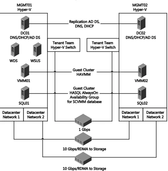
FIGURE 1-2 An architectural representation of the management infrastructure
With your management nodes deployed by means of your chosen operating system deployment mechanism, you’ll move on to enabling the Hyper-V role, transforming the standalone physical Windows Server instances into a pair of powerful virtualization hosts. Before you create your management VMs, you’ll need to manually configure some of the core Hyper-V settings. The most important of these settings, at least at this stage, is the creation of 8 CHAPTER 1 Design and planning
a virtual switch, which will allow your management VMs to communicate over the physical TenantNetwork.
The Hyper-V virtual switch, or vSwitch, is a Layer 2 (L2) virtual network switch that provides programmatically managed and extensible capabilities to connect VMs to the physical network. The vSwitch provides policy enforcement for security, isolation, and service levels. With support for Network Device Interface Specification (NDIS) filter drivers and Windows Filtering Platform (WFP) callout drivers, the Hyper-V vSwitch allows for third-party extensible plug-ins that can provide enhanced networking and security capabilities. In this POC configuration, you won’t be exploring any of these switch extensions. However, going forward, if you wish to evaluate technologies such as the Cisco Nexus 1000V, 5nine’s Security Manager, NEC’s PF1000 ProgrammableFlow virtual switch, or InMon Corp.’s sFlow switch extension, it’s important to know that all of these technologies integrate through this extensible Hyper-V vSwitch.
With the Hyper-V vSwitch defined, you’ll create management VMs that will provide the management backbone for the rest of the infrastructure. In Chapter 2, you’ll deploy a total of eight management VMs, as follows:
Domain controllers (DC01 and DC02) These VMs will be configured as a primary and secondary set of domain controllers, providing Active Directory Domain Services for a new domain, contoso.com, and forest. Both the domain and forest will be configured to operate at a Windows Server 2012 R2 functional level. The domain controllers will be distributed across MGMT01 and MGMT02. In addition to the Active Directory Domain Services, the domain controllers will both serve as Domain Name System (DNS) servers, providing name resolution for the contoso.com domain.
WDS The WDS VM will be configured as a single WDS server and will enable the subsequent deployment of Windows operating systems over the network. This removes the requirement for DVD or USB deployment. Later, the WDS server will be integrated with System Center Virtual Machine Manager to orchestrate thedeployment of the storage and compute nodes.
WSUS The WSUS VM is not necessarily essential for a POC configuration, but it will allow you to centrally manage and distribute updates to the other machines within the contoso.com POC configuration. This WSUS server will download updates for operating systems and applications to a central source and deploy them to target servers across the local network, ensuring each server does not have to download updates from the Internet directly. Having WSUS configured will help to ensure that servers and applications are fully up to date with both security and feature-related patches and fixes.
SQL Server database services (SQL01 and SQL02) The SQL Server VMs will provide the necessary database services for the System Center Virtual Machine Manager deployment. Without SQL Server, System Center Virtual Machine Manager cannot be installed and used, so SQL Server plays a pivotally important role within the management backbone. With that in mind, the two SQL Server VMs will bedistributed across the two management nodes and configured as a SQL Server
AlwaysOn Availability Group. The AlwaysOn Availability Groups feature is a high-availability and disaster-recovery solution that provides an enterprise-level alternative to database mirroring. The use of AlwaysOn Availability Groups in this POC
configuration will maximize the availability of the System Center Virtual Machine Manager database, without the need, in this case, for shared storage.
System Center Virtual Machine Manager servers (VMM01 and VMM02) The System Center Virtual Machine Manager VMs will host the Virtual Machine Manager component of the System Center product. System Center Virtual Machine Manager is a powerful and comprehensive management solution for the virtualized datacenter, enabling you to configure and manage your virtualization host, networking, and storage resources to create and deploy VMs and services to private clouds. In addition, System Center Virtual Machine Manager unlocks the power of network virtualization for the Hyper-V platform. You’ll use System Center Virtual Machine Manager to perform the vast majority of the management of the infrastructure. Because it plays such an important role in the management backbone, it’s imperative that it is as resilient and redundant as possible. With that in mind, System Center Virtual Machine Manager supports deployment in a highly available configuration, so VMM01 and VMM02 will be distributed across the underlying management nodes and across the two VMs that form a Windows Server failover cluster created to host the highly available System Center Virtual Machine Manager management service. This ensures that if one of the System Center Virtual Machine Manager management VMs suffers an outage, the other will take over to assure that you always have management control. You’ll explore many of the features of System Center Virtual Machine Manager as part of the POC configuration.
Library services (LIBRARY) Although you will not deploy library services until later in the POC configuration process, this library VM plays an important, integrated role with System Center Virtual Machine Manager. It enables the centralized storage of key System Center Virtual Machine Manager artifacts that System Center Virtual Machine Manager will use for deployment of Hyper-V hosts and VMs.With the management VMs deployed, you’ll use the management backbone that is now established to deploy the remaining network, storage, and compute infrastructure. With the shared storage deployed, you’ll be able to transform your standalone management nodes, MGMT01 and MGMT02, into a more resilient, robust management cluster by using the powerful failover cluster capabilities that are built into Windows Server 2012 R2. By
transforming the standalone nodes into a failover cluster and migrating the VM workloads— specifically their virtual hard disks and configuration files—to the shared storage, you will increase the levels of redundancy and resiliency considerably. This is of incredible importance for the management infrastructure.
The key benefit of using a failover cluster, rather than leaving the management nodes as standalone servers, is automated failover and increased redundancy. With the management VMs running on a failover cluster and their virtual hard disks and configuration files on shared 10 CHAPTER 1 Design and planning
storage, if a management node fails, the management VMs on that failed node will
automatically restart on the other management node within the failover cluster. This will take place without any intervention from you. This extra level of resilience and redundancy is important in ensuring the highest levels of availability for the infrastructure.
As mentioned in the discussion of the required memory for each management node, during a maintenance window, all VMs will run on a single management node while the other is patched and potentially rebooted. The exception is the domain controllers. When your shared storage is configured and deployed and all of the configuration files and virtual hard disks for the WSUS, WDS, SQL Server, and System Center Virtual Machine Manager servers have been migrated onto the shared storage, you’ll leave the domain controllers, DC01 and DC02, running on the local storage of MGMT01 and MGMT02, respectively.
Madness, you may think. You want the domain controllers to be as resilient and redundant as possible, so storing their virtual hard disks and configuration files on shared storage makes perfect sense. There is, however, method to the madness. If you were to store the domain controllers on the shared storage and an outage occurred with the shared storage, the domain services would be unavailable. The unavailability of the domain services would make bringing the rest of the infrastructure back online potentially more difficult due to a variety of circular dependencies. Leaving the virtual hard disks and configuration files for DC01 and DC02, your domain controllers, on the local storage of MGMT01 and MGMT02, respectively, reduces the number of potential complications and simplifies troubleshooting in the event of an outage. You can configure DC01 and DC02 to automatically start when MGMT01 and MGMT02 start up. Because they reside on local storage, they have no reliance on the shared storage or compute infrastructures to be online and ready.
Logical networking
With the management cluster configured and the management VMs providing a robust control plane, you can begin to use System Center Virtual Machine Manager to design and architect the logical networking configuration that you will be using throughout the rest of the deployment.
This POC configuration has two core networks: one that runs at a speed of 1 Gbps and another that runs at a speed of 10 Gbps. The 1-Gbps network will be used predominantly for the VMs in the environment and the BMCs for each physical server. Note that some models of BMC operate at 1-Gbps speed and others may only operate at 100 Mbps. Either way, we will refer to the network as having 1-Gbps speed. The other core network, the 10-Gbps network, will provide multiple functions for the POC configuration. It will carry storage traffic between the storage nodes (FS01 and FS02) and the management, compute, and gateway nodes. In addition, it will be used for live migration traffic as VMs are migrated between the respective management and compute nodes. In addition, this 10-Gbps network will carry management traffic. These two core networks will each be mapped into a System Center Virtual Machine Manager construct known as a logical network.
FIGURE 1-3 An architectural representation of the Tenant_LN and Datacenter_LN logical networks
At a high level, logical networks are named networks that serve particular functions in your environment. For example, the Backend, Frontend, or Backup network. In this POC
configuration, you will ultimately create two logical networks. As shown in Figure 3, the 1-Gbps TenantNetwork is labelled as Tenant_LN and the 10-1-Gbps DatacenterNetwork is labelled as Datacenter_LN. The functions of these two logical networks is simple: The Tenant_LN logical network will ultimately carry tenant traffic (from tenant VMs) but also will be used for the management VMs and the BMCs. The Datacenter_LN logical network will be used for infrastructure traffic, as mentioned earlier, which includes storage, live migration, and management traffic.
A logical network is a container for network sites (also called logical network definitions) and for IP subnet information, virtual local area network (VLAN) information, or both. Host groups in System Center Virtual Machine Manager can be associated with a network site, and IP address pools can be assigned to subnets within the logical network. In this small POC configuration, you will configure an individual network site for both the Tenant_LN logical network and the Datacenter_LN logical network (Tenant_LN_0 and Datacenter_LN_0,
respectively). Within these sites, you will configure the appropriate IP subnets and IP pools that 12 CHAPTER 1 Design and planning
System Center Virtual Machine Manager will use to distribute IP addresses to physical machines or VMs that reside on that network.
Notice in Figure 1-3 that the Tenant_LN logical network has a single subnet, 10.10.0.0/24, and corresponding IP pool from 10.10.0.100 to 10.10.0.250. System Center Virtual Machine Manager will distribute IP addresses from that range to new VMs later in the POC
configuration process. Also notice that the Datacenter_LN logical network has two subnets, 10.10.1.0/24 and 10.10.2.0/24, each with a corresponding IP pool. The reason for creating two subnets for the Datacenter_LN logical network, each with a corresponding IP pool, is to embrace a key capability known as Server Message Block (SMB) multichannel, which you’ll learn more about later. Essentially, when System Center Virtual Machine Manager configures your storage, compute, and gateway nodes, one of the 10-Gbps network adapters on each node is given an IP address on the 10.10.1.0/24 subnet and the other 10-Gbps network adapter on each node is given an IP address on the 10.10.2.0/24 subnet. Separating these ports on different subnets allows each of these nodes to take advantage of SMB multichannel.
It’s important to note that although the Tenant_LN and Datacenter_LN logical networks have different subnets, they are routable. Therefore, your management VMs, which will ultimately reside on the Tenant_LN logical network and have an IP address in the range of 10.10.0.0/24, can still communicate and manage the nodes that reside on the 10.10.1.0/24 and 10.10.2.0/24 subnets. This routing would typically be configured on your switches. In a production environment, it’s also important to note that these logical networks could be isolated from one another by means of a VLAN. Again, you would configure the appropriate routing at the switch level to route between the logical networks where appropriate, for instance, where the management VMs on the Tenant_LN logical network need to
communicate with physical hosts residing on the Datacenter_LN logical network. The aim of this POC configuration is to keep the logical networking as simple and as flat as possible, which is why VLAN 0 has been used throughout.
By configuring all of your logical networks, network sites, IP subnets, and IP pools before deploying your storage, compute, and gateway nodes, you are putting steps in place to significantly streamline the deployment and configuration process of those respective nodes later. As you’ll learn shortly, when you use System Center Virtual Machine Manager to deploy your storage, compute, and gateway nodes, it will apply the relevant logical network settings in a predictable and controlled manner at deployment time. This ensures that your storage, compute, and gateway nodes integrate seamlessly with your existing setup as quickly as possible, without you having to perform any network-related configuration post-deployment.
Logical networks enable you to model your network design and requirements effectively. You will take advantage of several other networking constructs within System Center Virtual Machine Manager as part of this POC configuration. One of those key constructs is the logical switch. You’ll learn considerably more about the logical switch and its core building blocks in Chapter 3, “Configuring network infrastructure”. At a high level, logical switches allow VMs to communicate out through the physical adapters and network adapter teams configured on a Hyper-V host. Because System Center Virtual Machine Manager is not available when you first
deploy your management nodes, you do not have the ability to use the logical switch. It is a System Center Virtual Machine Manager-only construct, which is why you will deploy a standard Hyper-V vSwitch to those management nodes. A logical switch still harnesses those same Hyper-V vSwitch capabilities but offers greater management granularity and control from within System Center Virtual Machine Manager.
Logical switches can also enforce standard configurations on Hyper-V host adapters and NIC teams to prevent workloads from experiencing downtime due to misconfigurations. For instance, if someone logged on to the Hyper-V host directly and made a configuration change to the vSwitch, System Center Virtual Machine Manager could detect and remediate this to bring the vSwitch back in line with its original deployment configuration. This is a capability unique to a logical switch.
As part of the POC, you will create a single logical switch and all of the core building blocks that it consists of. Upon deployment of your compute and gateway nodes, System Center Virtual Machine Manager will automatically aggregate the 1-Gbps network adapters in each respective host into a network team and bind the logical switch to that team. When your nodes have completed the deployment process, they will all have an identical, standardized instance of the logical switch across each node, ensuring efficient ongoing management and consistent operations.
Storage
If we’d looked at a traditional datacenter when designing the storage configuration for this POC, we’d most likely have landed on the use of either an iSCSI or Fibre Channel-based storage area network or SAN. iSCSI and Fibre Channel SANs have been the storage
deployment of choice within the datacenter for a considerable time, and for some datacenters, that will continue for years to come.
Have you ever taken the time to think just what a SAN is, what’s inside the chassis, and what it provides to the infrastructure?
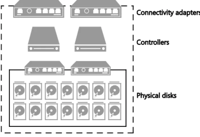
FIGURE 1-4 Conceptual layout of SAN storage
If you were to peek inside the chassis, as shown in Figure 1-4, you’d very likely find three key elements. First, you’d have physical disks. These could be exclusively Serial Attached SCSI (SAS) or Serial Advanced Technology Attachment- (SATA-) based HDDs with large capacities and speeds that could vary from 7,200 RPM up to 15,000 RPM. In addition, within more modern SANs, you may find SSDs with smaller capacities but significantly higher performance. The SSDs are typically in addition to the HDDs. In some SANs, you’ll find only SSDs, which provides incredible performance but at significantly higher cost.
To transform that raw capacity into usable storage, you’ll find the controller, or in most cases, controllers. Two or more controllers provide the brains of the SAN, transforming the physical disks into aggregated pools of redundant storage in the form of aggregates, volumes, or logical unit numbers (LUNs), depending on your SAN specifics. If you were to look inside one of these controllers, you’d likely find a modern x86 processor, memory, and perhaps some sort of local storage, on which perhaps a bespoke, heavily customized operating system is running. With two or more controllers, you have redundancy against failure, but you also have redundancy at times of maintenance and firmware updates. Aside from aggregating the storage into usable striped or mirrored volumes, these controllers provide advanced features such as deduplication, thin provisioning, rapid cloning, snapshots, storage tiering, and more. It’s these advanced features, combined with the reliability and redundancy associated with SANs, that drive so many organizations to choose them as their preferred infrastructure storage.
The final element within the SAN is the connectivity. How do you present the usable storage that you, the administrator, have created from the raw physical disks? With many SANs, you have a choice. iSCSI connectivity may be the preference since it uses the Ethernet network as transport and can support both 1-Gbps and 10-Gbps connectivity. Alternatively, perhaps Fibre Channel is the preferred connection option because it has always been perceived as a higher performing option. However, Fibre Channel brings a requirement for specific Fibre Channel switches and host bus adapters (HBAs), and this typically drives the cost of a Fibre Channel deployment higher than an equivalent iSCSI-based deployment. It’s typical for storage vendors to offer an either/or approach to connectivity, but some SANs do enable a network and Fibre Channel connectivity offering in the same chassis.
It’s interesting to understand the core building blocks of a SAN. However, for this POC configuration, you’ll be taking a different approach. The design of the storage infrastructure for this POC shares many similarities with the SAN-breakdown you just read, but this Microsoft software-defined storage (SDS) infrastructure is constructed from low-cost, high-volume hardware, transformed with the power of software.
At first glance, the conceptual layout, as shown in Figure 1-5, of the Microsoft SDS infrastructure looks similar to that of the SAN. While there are similarities, there are also a number of differences.
FIGURE 1-5 Key storage elements in the server and JBOD infrastructure
First, you have the physical disks. Again, this is similar to the SAN. These could be SAS- or SATA-based HDDs or SSDs. This time, instead of being contained within a SAN, they are contained with an external JBOD enclosure. This configuration will be using two 12-bay JBOD enclosures, for a total of 24 disk drives. When you deploy in a production environment, the best practice is to have SSDs as at least 20 percent of the drives and HDDs as the remaining 80 percent. An important best practice is that they be SAS-based HDDs and SSDs because these offer greater performance and reliability than SATA equivalents.
Within each JBOD enclosure are typically multiple SAS interfaces. These will be used to connect the respective JBOD enclosures to the controllers, which, in the Microsoft SDS solution and in this POC configuration, will be a pair of Windows Server 2012 R2 servers (FS01 and FS02). The SAS interfaces should each be multimaster- or multiserver-capable. The drives within the enclosures must support port association. Multiport drives must provide symmetric access, and drives must provide persistent reservations.
To identify disks by slot and take advantage of the enclosure’s failure and identify/locate lights, the JBOD enclosures must support SCSI Enclosure Services (SES) version 3. In addition, the enclosure must provide direct access to the drives that are housed within the enclosure. It’s important not to apply any abstraction to the drives such as grouping drives into a RAID array. The drives should be presented raw to the Windows Server 2012 R2 controller nodes. Finally, the JBOD enclosure must provide multiple SAS interfaces to the drives and to the controllers to provide the highest levels of reliability and redundancy.
For a specific list of JBOD enclosures that are supported with Windows Server 2012 R2, refer to the Windows Server Catalog at
http://windowsservercatalog.com/results.aspx?&chtext=&cstext=&csttext=&chbtext=&bCatID=1 645&cpID=0&avc=10&ava=80&avq=0&OR=1&PGS=25&ready=0.
As mentioned earlier, the JBOD enclosures will be connected to the Windows Server 2012 R2 controller nodes by means of industry-standard SAS cables, at either 6-Gbps or 12-Gbps
speed, depending on your specific JBOD enclosure and the SAS interfaces within your controller nodes.
The SAS interfaces within your Windows Server 2012 R2 controller nodes should be at least 6 Gbps. If you are using RAID adapters instead of SAS HBAs, they must be in non-RAID mode with all RAID functionality disabled. Such adapters must not abstract the physical disks or cache data or obscure any attached devices, including enclosure services provided by the JBOD enclosures.
Continuing through the layers of the conceptual architecture, you have the controllers. In the SAN configuration that was discussed earlier, multiple controllers were available for redundancy. In addition, these controllers provided the intelligence to wrapper the physical disks with advanced features and functionality. Using multiple Windows Server 2012 R2 servers as the controller nodes provides similar capabilities as part of the Microsoft SDS solution.
With the raw physical drives presented from the JBOD enclosures through to both FS01 and FS02, you’ll use the advanced functionality of Windows Server 2012 R2 to greatly simplify storage management and storage virtualization while creating reliable, highly available storage.
FIGURE 1-6 Microsoft Software Defined Storage layers
You’ll transform these raw physical drives into a single storage pool. As shown in Figure 1-6, these storage pools are virtualized units of administration that are aggregates of underlying physical disk drives. They aggregate the capacity but also allow for elastic capacity expansion if you add more drives, and delegated administration. When combined with Failover Clustering, the clustered pool can be used by any node in the file server cluster and fail over within the failover cluster. This is useful to automatically recover from failures, as well as for load balancing workloads.
From there, you’ll slice that pool into a number of storage spaces. Storage spaces are virtual disks with attributes that include a desired level of resiliency, fixed or thin provisioning, automatic or controlled allocation of heterogeneous classes of storage, and precise administrative control. In the traditional SAN world, this would equate to creating a LUN or volume from your aggregated set of disks.
Windows Server 2012 R2 supports aggregating HDDs and SSDs into a single, logical disk, or storage space, allowing configurations that seamlessly provide both the high capacity of HDDs and the high performance and low latency of SSDs. HDDs and SSDs are defined as different tiers as part of the same storage space. Even though there are two distinct classes of hardware, a tiered space is presented as a seamless, unified disk. File systems will track how frequently data located on the tiered space is accessed and will periodically automatically move frequently accessed data to the portion of the tiered space backed by SSDs. Infrequently accessed data will similarly be moved to the portion of the tiered space backed by HDDs. Frequently accessed data will be stored on SSDs, providing low latency access to applications. Infrequently accessed data will be stored on low-cost, high-capacity HDDs, ensuring that data placement is responsive to varying workload conditions. In Windows Server 2012 R2, storage tiering is compatible only with simple or mirrored storage spaces.
A single storage space and the file system that resides on top of the storage space are controlled or resident on exactly one storage node at a time. Using Failover Clustering, the storage space can move to a different storage node within the cluster. The movement of a storage space will occur if the original storage node is no longer functional. The storage space can also be moved if necessary to achieve a balanced load within the storage nodes of the cluster. Layering Cluster Shared Volumes (CSVs) on top of the storage space/file system combination creates a clustered file system that all services on any storage node in the cluster can then access. If a storage space is moved anywhere within the cluster, CSV will transparently redirect all I/O from the service that is using the file system or storage space to the new storage node that the file system or storage space resides on.
Ultimately, by transforming your Windows Server 2012 R2 controller nodes FS01 and FS02 into a file server cluster and with that configuring clustered storage pools, spaces, and CSVs, you’re in a position to deploy the SOFS feature. SOFS is a feature that is designed to provide scale-out file shares that are continuously available for file-based server application storage. SOFS shares provide the ability to share the same folder from multiple nodes of the same cluster and are therefore perfect to store the Hyper-V VMs that will run on your compute, management, and gateway nodes.