NX1010 Video Exploitation
Processor
(NX1010VEPEX)
12/9/2014
175-100146-00 Rev B
Publication Information
© 2014 Imagine Communications Corp. Proprietary and Confidential.Imagine Communications considers this document and its contents to be proprietary and confidential. Except for making a reasonable number of copies for your own internal use, you may not reproduce this publication, or any part thereof, in any form, by any method, for any purpose, or in any language other than English without the written consent of Imagine Communications. All others uses are illegal. This publication is designed to assist in the use of the product as it exists on the date of publication of this manual, and may not reflect the product at the current time or an unknown time in the future. This publication does not in any way warrant description accuracy or guarantee the use for the product to which it refers. Imagine Communications reserves the right, without notice to make such changes in equipment, design, specifications, components, or documentation as progress may warrant to improve the performance of the product.
United States Government Legend
If you are a United States government agency, then this documentation and the software described herein are provided to you subject to the following:
All technical data and computer software are commercial in nature and developed solely at private expense. Software is delivered as “Commercial Computer Software” as defined in DFARS 252.227-7014 (June 1995) or as a “commercial item” as defined in FAR 2.101(a) and as such is provided with only such rights as are provided by Imagine Communications’ standard commercial license for the Software. Technical data is provided with limited rights only as provided in DFAR 252.227-7015 (Nov 1995) or FAR 52.227-14 (June 1987), whichever is applicable. You agree not to remove or deface any portion of any legend provided on any licensed program or documentation contained in, or delivered to you in conjunction with, this User Guide.
Trademarks
Product names and other appropriate trademarks, e.g. D-Series™, Invenio®, PowerSmart®, Versio™ are trademarks or trade names of Imagine Communications or its subsidiaries.
Microsoft® and Windows® are registered trademarks of Microsoft Corporation. All other trademarks and trade names are the property of their respective companies.
Support Contact Information
For domestic and international support contact information see:
Support Contacts (http://www.imaginecommunications.com/services/customer-care.aspx) eCustomer Portal (http://support.imaginecommunications.com)
Contents
About This Guide
... 1Intended Audience ... 1
Finding Specific Information in This Guide ... 2
Writing Conventions ... 2
Related Documentation ... 3
Obtaining Documentation ... 4
Purchasing Manuals ... 4
Unpacking/Shipping Information ... 5
Unpacking an Imagine Communications Product ... 5
Returning an Imagine Communications Product ... 5
Technical Support ... 6
Chapter 1 Using NX1010VEPEX
... 7Opening the jRCS Application ... 8
Setup the Inputs and Outputs ... 10
Modify Server Input Devices ... 13
Use Network Input Ports ... 13
Modify the Server Output Devices ... 19
Use Network Output Ports ... 20
Timestamping ... 37
GOP level timecode restamping (MPEG-2 video only) ... 37
Metadata timestamp generation (MPEG2 or H.264 video) ... 39
Service Aggregation ... 43
Generate MMS Service ... 45
Monitor Input Programs ...50
Properties Monitor ...55
Monitor Output Programs ...58
Manage VEP Files ...61
Upload files to the VEP ...61
Download Files from the VEP ...65
Rename Files on the VEP ...68
Delete Files on the VEP ...69
Administrator/Engineering Functionality ...69
Help Menu ...69
License Information ...70
About jRCS ...71
Appendix A
Administrator and Engineering Functionality ...73Overview ...74
User Access Levels ...74
Password Settings ...76
Default Passwords ...76
Change the Administration Password ...77
Change the Engineering Password ...78
Reset the Default Administration/Engineering Passwords ...79
Password Errors ...79
Manage User Settings ...79
Add Users ...79
Reset a User’s Password ...81
Edit a User’s Access Level ...82
Remove Users ...83
RAID Manager ...83
Engineering Tasks ...84
Set Logging Information Levels ...84
Appendix B
Troubleshooting/FAQs ... 87Hardware ... 87
Software ... 88
Failure to Start jRCS ... 88
Disconnected Input Stream ... 88
Additional Help ... 88
List of Procedures
To open the jRCS application ... 8
To Create VBR Input and Configure Correct Output Parameters ... 11
To change the server description ... 13
To change network device description ... 13
To add input ports to a network device ... 14
To change network device description ... 16
To remove network input port ... 16
To view the program properties for Server Inputs ... 17
To change server output description ... 19
To change network device description ... 20
To create an output ... 21
To add network outputs to a network device ... 22
To change output port description ... 23
To change multiplex parameters ... 24
To add a program to a network port ... 25
To move a program via drag and drop ... 27
To add existing services to an output multiplex ... 28
To generate an MMS Service ... 30
To edit LDS data ... 33
To remove a program from a network port ... 36
To enable GOP timestamping in MPEG2 Video: ... 37
To enable metadata timestamp in MPEG2 Video: ... 39
To Enable Metadata Timestamping in H.264 Video ... 41
To add existing input service to an output multiplex ... 43
To add MMS Service to an ouput program ... 45
To monitor your input programs ... 51
To view the properties for network output ports ... 56
To view the output program properties ... 57
To monitor your output programs ... 58
To upload files to the VEP ...61
To download files from the VEP to your local computer ...65
To rename files located on the VEP ...68
To delete files on the VEP ...69
To view license information ...70
To view jRCS information ...71
To Change the Administration Password ...77
To Change the Engineering Password ...78
To save configuration ...84
To load configuration ...85
About This Guide
About This Guide provides an overview of this guide, describes guide conventions, and tells you where to look for specific information. This section also provides important information on unpacking and shipping your product.
The NEXIO™ Video Exploitation Processor (NX1010VEPEX) is a transport stream remultiplexer. It receives one or more transport stream inputs and then outputs a single transport stream containing services aggregated from the input streams. Some transformations are performed on the streams to add time stamping information as well as potentially restamping the input timebase of some services.
The primary features of the VEP are:
UDP input/output
service aggregation
GOP level timecode restamping
metadata timestamp insertion
low latency (less than 250ms)
This guide describes procedures for configuration and use of the NEXIO Video Exploitation Processor.
If the information in the release notes shipped with your product differs from the information in this guide, follow the instructions in the release notes.
Intended
Audience
This table shows the location of specific information in this guide.
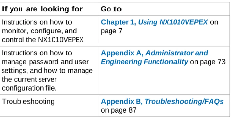
If you are looking for Go to
Instructions on how to monitor, configure, and control the NX1010VEPEX
Chapter 1, Using NX1010VEPEX on page 7
Instructions on how to manage password and user settings, and how to manage the current server
configuration file.
Appendix A, Administrator and
Engineering Functionality on page 73
Troubleshooting Appendix B, Troubleshooting/FAQs on page 87
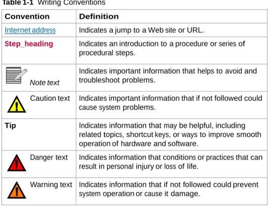
Writing Conventions
This guide uses the following writing conventions.
Table 1-1 Writing Conventions
Convention Definition
Bold Indicates dialog box, property sheet, field, button, check box, list box, combo box, menu, submenu, window, list, and selection names.
Italics Indicates e-mail addresses, names of books and publications, and first instances of new terms and specialized words that need emphasis.
CAPS Indicates a specific key on the keyboard, such as ENTER, TAB, CTRL, ALT, DELETE.
Code Indicates variables or command-line entries, such as a DOS entry or something you type into a field.
> Indicates the direction of navigation through a hierarchy of menus and windows.
Table 1-1 Writing Conventions
Convention Definition
Internet address Indicates a jump to a Web site or URL.
Step_heading Indicates an introduction to a procedure or series of procedural steps.
Note text
Indicates important information that helps to avoid and troubleshoot problems.
Caution text Indicates important information that if not followed could cause system problems.
Tip Indicates information that may be helpful, including related topics, shortcut keys, or ways to improve smooth operation of hardware and software.
Danger text Indicates information that conditions or practices that can result in personal injury or loss of life.
Warning text Indicates information that if not followed could prevent system operation or cause it damage.
Related Documentation
NEXIO NX1010MC/DS/VEP Quick Start
Obtaining Documentation
Manuals, User Guides and other documents can be viewed or downloaded from the eCustomer portal at
http://support.imaginecommunications.com/ecustomer_enu/
1 In the Customer Login area, enter your User and Password, and click Submit. OR
Click New User to register with Imagine Communications. The Imagine Communications Premier Welcome page displays.
Figure 1-1 Link to Support Documentation
2 Under the Table of Contents, click Servers and then select Compressed Media Servers.
3 Click on the title of the document, and click Open to view it. OR
Click Save to download the document.
Alternatively, contact your Imagine Communications customer service representative to request a document.
Unpacking/Shipping Information
The following sections describe: Unpacking an Imagine Communications Product
Returning an Imagine Communications Product
Unpacking a
Product
All NEXIO products have been carefully inspected, tested and calibrated before shipment to ensure stable and trouble-free service.
1 Check the equipment for any visible damage that may have occurred during transit.
2 Confirm that you have received all items listed on the packing list.
3 Contact your dealer if any item on the packing list is missing.
4 Contact the carrier if any item is damaged.
5 Remove all packaging material from the product and its associated components before you install the unit.
Returning a
Product
In the unlikely event that an Imagine Communications product fails to operate properly, contact the Imagine Communications NEXIO Customer Service Department to obtain a Return Authorization (RA) number, then send the unit back for servicing. Include the RA number on the outside of the return box. Keep at least one set of original packaging in the event that a product needs to be returned for service. If the original package is not available, you may purchase replacement packaging from Imagine Communications. Otherwise, you may supply your own packaging as long as it meets the following criteria:
The packaging must be able to withstand the product’s weight.
The product must be held rigid within the package.
There must be at least 2 inches (5 cm) of space between the product and the
container.
The corners of the product must be protected.
If the product is still within the warranty period, Imagine Communications will return it to you by prepaid ground shipping after servicing.
Technical
Support
For domestic and international support contact information see:• Support Contacts
(http://www.imaginecommunications.com/services/customer-care.aspx)
• eCustomer Portal (http://support.imaginecommunications.com)
• Academy Training
1
Using NX1010VEPEX
This chapter describes how to monitor, configure, and control the NX1010VEP using the jRCS application. For detailed instructions on installing and rack mounting the NX1010VEP hardware, refer to the NX1010 Hardware Guide for mCAPTURE and VEP (175-100138-00).
This chapter includes the following topics:
Opening the jRCS Application
Setup the Inputs and Outputs
Timestamping
Bandwidth Monitor
Properties Monitor
Monitor Output Programs
Manage VEP Files
Administrator/Engineering Functionality
Opening the jRCS Application
Use your browser to open the jRCS application and connect to the VEP. To connect to the VEP, you need to access the network that the VEP is on. Your network administrator also needs to ensure that you have access to port 49227 and 49230. To open the jRCS application
1 Open your browser.
2 Connect to the VEP by entering the URL, including the port number, in the browser Address bar. Use a colon to separate the VEP IP address and the port number. Example: http://137.237.182.118:49230
3 Press Enter to connect to the VEP.
The following jRCS Connection screen displays in the browser.
The following Security Warning window displays simultaneously.
Your administrator must create a user name and password in order for you to be able to connect to the VEP.
There are three levels of users: User, Admin, and Engineering.
5 Enter the IP address of the VEP in the Server field.
After entering this information once, this field will automatically contain the appropriate information each time the VEP Connection Manager displays in the future.
6 Enter your user name and password, and then click Connect. The jRCS
Setup the Inputs and Outputs
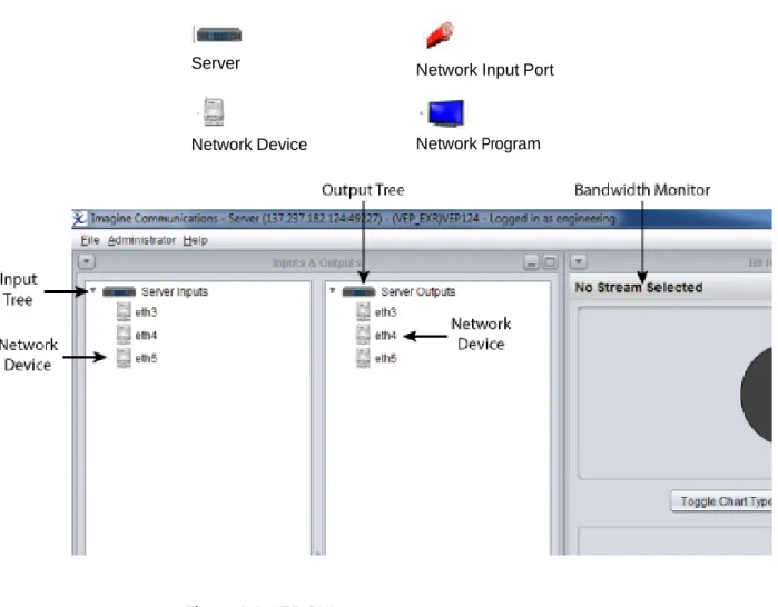
Use the Servers input and output trees to setup and organize your devices, ports, and programs.
The following icons are displayed in the Servers input and output trees:
Server Network Input Port
Network Device Network Program
To Create VBR Input and Configure Correct Output Parameters
1 If the input source is a VBR (Variable Bit Rate) stream, select Variable in the Add Input window
2 Select the Input Type and input correct Session Address and UDP port number, and click Create.
3 Click the Input Source, and then check the Properties panel to make sure the
Transport Stream Bit Rate field displays Variable.
4 To create the output, right-click on the Ethernet device and click Add Network Output.
The VEP output converts the VBR input to the CBR (Constant Bit Rate) stream.
5 To create a VEP output stream without errors, set the Output Latency to a value higher than 100ms (150ms is recommended).
Tip Because the VBR stream bit rate may spike frequently, set the output bit rate 50% above the nominal/average input rate. For instance, if the VBR input bit rate is approximately 2.3Mbps, the output bit rate should be set to at 3.45.
You can change the displayed name of the server and the devices.
The right-click menu on the Server Inputs includes the following options:
Change Descriptions
To change the server description
1 Right-click Server Inputs in the Server Input tree.
2 Select Change Description from the drop-down menu.
3 Enter a new description of the server in the New Description field.
4 Click Apply.
Use Network Input Ports
You can add input ports to your network device by using the right-click menu on the Server Inputs tree. After you add the network input port, you can change the port name and remove the port from the Server Inputs tree.
The right-click menu on the network input device includes the following options:
Change Description
Add Network Input
To change network device description
1 Right-click on the network device name in Server Inputs tree.
3 Enter a new description for the network input device in the New Description
field.
4 Click Apply.
To add input ports to a network device
1 Right-click on the network device name in the Server Inputs tree.
2 Select Add Network Input from the drop-down menu.
3
Th Se
e Input Description displays.
ect the Input Type from the drop-down menu.
For Unicast, you do not need to enter the Session Address or the Source Specific Address. Leave these fields blank.
For Multicast, you need to enter the Session Address in the Session Address
field. Leave the Source Specific Address field blank.
For Source Specific Multicast, you need to enter both Session Address and
4 Enter the Session Address.
5 Enter the UDP Port.
6 Enter the Source Specific Address.
7 Enter the TTL Port.
8 Select the Transport Stream Bit Rate. Choose Constant or Variable.
If you selected VBR as your Input Type (in step 3 above), then select VBR as the Transport Stream Bit Rate now.
9 Click Create to add the network input.
The newly created network input port displays in the Server Input tree.
The right-click menu on the network input port includes the following options:
Change Description
To change network device description
1 Right-click on the network device name in Servers Input tree.
2 Select Change Description from the drop-down menu.
3 Enter a new description for the network input device in the New Description
field.
Click Apply.
To remove network input port
1 Right-click on the network input port name in the Server Input tree.
2 Select Remove Input.
To view the program properties for Server Inputs
1 Right-click the icon to view the following program properties:
PMT PID
PCR PID
Video PID
KLV Metadata PID
3 Right-click Video PID to display the Video PMT Entry Information.
Modify the Server Output Devices
You can change the displayed name of the server and the devices.
The right-click menu on the Server Outputs includes the following options:
Change Descriptions
To change server output description
1 Right-click on the Server Outputs icon in the Server Output tree.
2 Select Change Description.
3 Enter a new name for the server in the New Description field.
Use Network Output Ports
You can add output ports to your network device by using the right-click menu on the Server Output tree. After you add the network output port, you can change the port name and remove the port from the Server Output tree.
The right-click menu on the network output device includes the following options:
Change Description
Add Network Input
To change network device description
1 Right-click on the network output port name in the Server Outputs tree.
To create an output
1 Right-click the Ethernet device and click Add Network Output.
VEP output will convert the VBR input to the CBR (Constant Bit Rate) stream. To let VEP output stream without errors, the user should set the Output Latency to a value higher than 100ms (150ms is recommended).
Because VBR stream bit rate will soar up frequently, it’s better to input the output bit rate 50% above the nominal/average input rate. For instance, if the VBR input bit rate is roughly at 2.3Mbps, the output bit rate should be set to 3.45.
To add network outputs to a network device
1 Right-click the Ethernet device.
2 Select Add Network Output
3 Enter a destination address.
5 Drag and drop the VBR input to the output port.
You can also add and modify output ports to your network device by using the right-click menu on the Server Outputs tree.
The right-click menu on the output port includes the following options:
Change Description
Change Multiplex Parameters
Add Program
Remove Program
To change output port description
1 Right-click on the output port icon in the Server Outputs tree.
2 Select Change Description.
3 Enter a new name for the output port in the New Description field.
To change multiplex parameters
1 Right-click on the port icon in the Server Outputs tree.
2 Select Change Multiplex Parameters.
The Set Multiplex Parameters screen appears.
3 Change any or all of the following:
4 Click Set Parameters.
Note the change in the Transport Stream ID from 50 to 60.
To add a program to a network port
1 Right-click on the output port icon in the Server Outputs tree.
2 Select Add Program.
The Add Program window appears.
3 The Program Number displays a default number that can be edited.
Once an Input Source is selected, the Program Services properties displays. See the following table for details on the Add Program options.
Option Description
PMT PID Displays the default PMT Program ID that you can edit. PCR PID Displays the default PCR Program ID that you can edit. Output PID Displays the Output Program ID
Input PID Displays the Input Program ID
Stream Type Displays the type of audio or video stream type for this program, including the following:
MPEG-1 audio
MPEG-2 audio
AC-3 Audio
MPEG-2 Video
H.264 Video
5 Click Create.
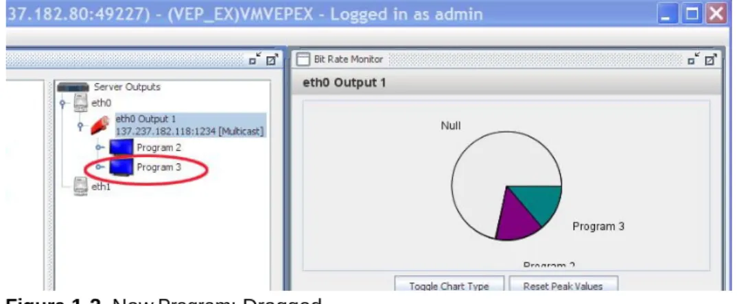
To move a program via drag and drop
1 Select the input program that you want to move from the Server Inputs tree and drag the program to the port icon in the Server Outputs tree.
2 Release the program on the output port. The Add a Program window displays.
3 Confirm that the PIDs (in the Program Services area) are not already being used. Change them if necessary, and then click Create.
Figure 1-2 New Program: Dragged
To add existing services to an output multiplex
1 Right-click the output program and select Add Service.
2 In the drop-down, select Add Service. The Add Service window appears.
3 Select the input source and the input PID.
4 Click Create to confirm adding the service.
To generate an MMS Service
1 Right-click the output program.
The Add Generated MMS Service window displays.
3 Define the MMS data PID and the repetition rate.
If UNCLASSIFIED is selected, then the Security-SCI, Caveats, and Releasing Instructions fields are not available.
5 Click Add to confirm adding the service.
To edit LDS data
If the input stream has the LDS metadata, the VEP can add it to the incoming LDS KLV data to output and edit the LDS data.
2 Select Asynchronous Metadata as the Stream Type.
The newly added KLV data PID appears under the output program.
3 Select Edit LDS Data from the drop-down. The Edit LDS Data window appears.
A floating tool tip is available for the following editable fields. You can access the tool tip by right-clicking on the field.
Enforce MMS Compliance Select this check box to ensure that the
LDS Field Right-click the selected LDS field to view its tag number.
State Right-click the selected State to view the drop-down options of the various filter modes (insert, overwrite, pass-through, remove).
4 Click Pass Through All (located in the upper right hand corner) to allow VEP to pass-through all incoming data to the output data. If you want to modify the output data, you should change the State to Insert.
To remove a program from a network port
1 Right-click on the output port icon in the Server Outputs tree.
2 Select Remove Program.
The Remove Output dialog box appears.
3 Click Remove to remove this output.
Timestamping
The VEP supports two forms of timestamping:
GOP level timecode restamping (MPEG-2 video only) on page 37
Metadata timestamp generation (MPEG2 or H.264 video) on page 39
GOP level timecode restamping (MPEG-2 video only)
GOP level timestamping replaces the timecode field in the GOP header (in MPEG-2 video). The user may choose one of two methods for the replacement. The methods differ only in how the initial timestamp is selected. In the first method, the initial timecode is taken to be the current time of day (in local time) expressed as hh:mm:ss:ff. The frames portion is calculated based on the partial seconds of the current time. In the second method, the user specifies the initial timecode. Once the initial timecode has been selected, both methods calculate subsequent timecode values in the same way. Subsequent timecode values are based on the video stream timebase. The difference between the PTS timestamps of frames is used to calculate the next timecode value from the previous one.
1 Select the valid MPEG2 video in the output tree.
2 Right-click the MPEG2 video.
A timestamping drop-down menu displays.
3 Select Enable MPEG2 Timecode Restamping. The Enable Timecode Restamping dialog displays.
4 Select Use Specified Timecode to attach the user customized timecode or the UTC system time will be used as the default.
5 Select Drop Frame if you need, otherwise it remains deselected by default.
6 Click Enable.
Metadata timestamp generation (MPEG2 or H.264 video)
When metadata timestamp generation is used, a snapshot of the current time of day (UTC) is taken whenever an I-frame is seen. This timestamp is coded into a KLV timestamp as per SMPTE-336M-2001 and scheduled into the multiplex as a synchronized metadata packet as per MPEG-2 13818-1(2000)/Amd-1(2003). The metadata timestamp generation creates a new PID in the transport stream. To enable metadata timestamp in MPEG2 Video:
1 Select the valid MPEG2 video in the output tree.
A timestamping drop-down menu displays.
3 Click Enable Metadata Timestamping.
In the output tree, the Metadata PID appears under the Video PID.
To Enable Metadata Timestamping in H.264 Video
2 Right-click the H.264 video.
A timestamping drop-down menu displays.
3 Click Enable Metadata Timestamping.
The Enable Metadata Timestaming dialog displays.
4 Input the metadata PID and Service ID, and then click Enable. In the output tree, the Metadata PID displays under the Video PID.
Service Aggregation
Service aggregation is used to add existing input services to an output multiplex. To add existing input service to an output multiplex
1 Right-click the existed output program, and select Add Service.
Generate MMS Service
MMS is compatible to MISB STANDARD 0902.1. To add MMS Service to an ouput program
1 Right-click on the existing output program, and select Generate MMS Service.
2 In the Add Generated MMS Service dialogue, define the MMS data PID and repetition rate.
3 Select the Security Classification from the drop-down list. Security-SCI, Caveats and Releasing Instruction are not available to fill if the security level is
UNCLASSIFIED.
4 Click Add to confirm adding service.
Edit LDS Data and Data Filter
VEP can edit either existed LDS KLV data in the output program, or aggregated LDS KLV data.
1 Right-click on the KLV data PID and select Edit LDS Data (see Add Service Aggregation on page 43 to add the LDS KLV data if it’s not in the output).
2 Select Asynchronous Metadata from Input Source.
Floating tool tip explains every editable field: a Enforce MMS Compliance.
b In the LDS Field column, the tool tip displays the tag number.
c In the State column, tool tip explains the different filter modes (insert, overwrite, pass-through, and remove).
4 The VEP passes through all incoming data to the out put data. If you want to modify the output data, change the State to Insert.
5 In Insert State, input the data in the User-Specific column. After you input the new data, press Enter to save changes.
6 To make the output data compliant to the MISB STD 0902, check Enforce MMS Compliance on the top left dialogue.
7 To discard all changes made previously, click Pass Through All on the top right of dialogue.
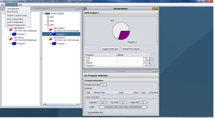
Bandwidth Monitor
The VEP jRCS application includes a Bandwidth Monitor that allows you to monitor the bitrate usage for the selected Transport Stream. You can view your program bitrate usage as a pie chart/bar graph and in a summary table.
The bitrate is measured in megabits per second and is integrated over a sampling period of one second.
To monitor your input programs
1 Click on the device icon in the Server Inputs tree.
The Bandwidth Monitor displays the following information on the right side of the screen:
The pie chart or bar graph displays each program’s bandwidth as a graphical
percentage for the selected board. All null values are displayed in grey.
2 Click on Toggle Chart Type to switch between the pie chart and bar graph display (see To view the output program properties on page 57).
The table displays each program’s bitrate usage in megabits per second for the
Pie Chart/Graph
Reset Peak Values Button Toggle Chart Type Button Table
You can view the program details by clicking on the desired Program.
Click on Program to view details
The right side of the table updates to show specific program information, including service, bitrate PID and type.
4 Hover your mouse over the arc in the pie chart or the label in the bar graph to quickly view the bandwidth used for a program.
A tooltip displays the average megabits per second for the program and the peak megabits per second for the program.
Tip For both Input and Output Server devices, you can change the view of the
Bandwidth Monitor and the Properties screen.
You can click on the minimize/maximize icon found in the upper right-hand corner of each monitor to change the view of the Bit Rate Monitor
and Properties Monitor. When the monitors are minimized, they will be reduced and can be found in the lower left-hand corner.
Figure 1-4 Minimized Bit Rate Monitor
To return to the full view of the monitor, click on the Bit Rate Monitor bar in the lower left-hand corner.
Properties
Monitor
The VEP jRCS application includes a Properties Monitor that allows you to view the details for the selected Transport Stream.
The Properties Monitor displays detailed information on selected network ports and programs.
The Properties Monitor displays the properties of the selected network ports and programs.
To view the properties for network output ports
1 Click on the desired output port to view the properties.
(See To view the output program properties on page 57 for an example of an output port properties display.)
The out port properties that display include the following:
Ethernet Information
Type
IP Address
TTL
Port
Multicast Loopback
Multiplex Stream Information
Bit Rate
PAT Interval
Transport Stream ID
To view the output program properties
1 Click on the desired output program to view the properties.
The program properties that display include the following:
PMT Information
PMT PID
PCD PID
PMT Entries
PID
Type
Monitor Output Programs
To monitor your output programs
1 Click on the device icon in the Server Inputs tree.
The Bandwidth Monitor displays the following information on the right side of the screen:
The pie chart or bar graph displays each program’s bandwidth as a graphical
percentage for the selected board. All null values are displayed in grey.
2 Click on Toggle Chart Type to switch between the pie chart and bar graph display.
The table displays each program’s bitrate usage in megabits per second for the
selected board. The table displays below the pie chart or bar graph.
Click on Program to view details.
3 Select a specific program in the left table column to view the details.
The right side of the table updates to show specific program information, including service, bitrate, PID, and type.
4 Hover your mouse over the arc in the pie chart or the label in the bar graph to quickly view the bandwidth used for a program.
A tooltip displays the average megabits per second for the program and the peak megabits per second for the program.
Tooltip
To view the properties for network output ports
The output properties that display include the following:
Ethernet Information
Type
IP Address
TTL
Port
Multicast Loopback
Multiplex Stream Information
Bit Rate
PAT Interval
Transport Stream Id
PMT Interval
Manage
VEP Files
The File Transfer Manager allows you to manage the files on your VEP.
You can use the File Transfer Manager to:
Upload files to the VEP
Download files from the VEP
Rename files on the VEP
Delete files on the VEP
Upload files to the VEP
To upload files to the VEP
The list includes the following:
Clip
Config
Infolog
Static_psip
Harris_playlist
Harris_asrun
Harris_capture
Psip_database_snapshot
License
Once you select a file type, the Server Files area displays the files on the VEP server that match the select file type.
3 Select the desired file from the Server Files area, and then click Add File to upload a file to your VEP.
4 Click the down arrow beside the Look In field and navigate to the file you want to upload.
5 Select the desired file and click Open. The Transfer Status window opens.
The Transfer Status window monitors your transfer progress.
The Transfer Status bar provides a visual status of the upload process.
6 Select the Close on completion checkbox to close the Transfer window automatically once the file has completed uploading to the VEP.
Download Files from the VEP
To download files from the VEP to your local computer
1 Select File > File Transfer Manager. The File Transfer Manager opens.
The list includes the following:
Clip
Config
Infolog
Static_psip
Harris_playlist
Harris_asrun
Harris_capture
Psip_database_snapshot
License
Once you select a file type, the Server Files area displays the files on the VEP server that match the select file type.
3 Select the desired file from the Server Files area, and then click Get File to download a file from your VEP.
4 The Save dialog displays with the current directory displayed in the Save In field.
5 Click the down arrow beside the Save In field and navigate to the location on your local computer where you want to save the file.
6 Select the desired file and click Save.
Immediately following the Transfer Pending window, the Transfer Status
window displays.
The Transfer Status window monitors your transfer progress.
The Transfer Status bar provides a visual status of the upload process.
7 Select the Close on completion checkbox to close the Transfer window automatically once the file has completed uploading to the VEP.
Rename Files on the VEP
To rename files located on the VEP
1 Select File > File Transfer Manager. The File Transfer Manager opens.
2 Select the file that you want to rename, and then click Rename. The Rename window displays.
3 Enter a new name for the file, and then click Apply. The new file name displays in the Server Files area.
Delete Files on the VEP
To delete files on the VEP
1 Select File > File Transfer Manager. The File Transfer Manager opens.
2 Select a file type.
3 Select the file(s) you want to delete from the list of files in the Server area.
4 Click Delete.
A Confirm Delete window displays, asking you to confirm the deletion.
5 Click Yes to delete the file from the VEP server, or click No to cancel the delete. The dialog will close and the file will be deleted (and removed) from the Server Files list.
Administrator/Engineering Functionality
For detailed information on administrator and engineering functions, see Appendix A, Administrator and Engineering Functionality on page 73.
Help Menu
The VEP Help Menu includes the following:
License Information About the jRCS
License Information
Figure 1-5 Help Menu To view license information
1 Go to Help > License Information. The License Info window displays.
About jRCS
To view jRCS information1 Go to Help > About the jRCS. The About jRCS window displays.
The server and client version numbers display.
A
Administrator and
Engineering Functionality
This appendix describes how to manage password and user settings. It also describes how to manage the current server configuration file.
Topics in this appendix include:
Overview on page 74
Password Settings on page 76
Manage User Settings on page 79
Overview
The jRCS administrator functionality is located on the Administrator menu, which is only available if you are logged in as a user with administrator or engineering privileges.Figure A-1 Administrator Menu
User Access
Levels
The three types of users include: General User, Admin, and Engineering. Each user type has different access levels to the VEP via the jRCS. There can be an unlimited number of Users and Admins but there can be only one Engineering account.
The following table defines the access level to the jRCS functionality for each type of user.
Menus Access General User Admin Engineer
File Menu File Transfer Manager Reset the VEP Disconnect Exit JRCS
Configuration Menu
Load Config Save Config
Admin Menu User Manager
Unload Config Info Levels
VEP Input Tree General User Admin Engineer
VEP Node Change Description
VEP Output Tree
VEP Node Change Description
Set Maximum Video Bandwidth
Set Transport ID
Set PAT Interval Set PCR Interval Set PMT Interval
Set Max End To End Delay ASI Settings Set Clock Source
Set Bypass Timeout Configure PSIP Remove Output
VEP Output Tree General User Admin Engineer
Service Nodes (all)
Alias Node
Hide Service Hide Service Remove Service Remove Service
Change Description
Set Buffer Multipliers
Pass-Thru Node
Activate Output
Add Service Remove Program
Activate Output
Hide Program Add Service Remove Program
Drag and Drop General User Admin Engineer
Add Program Advanced Button
Max Video Frame Size
Video Buffer Count
Password
Settings
Administrators and engineers control the username and password needed to access the VEP using the jRCS application. The password options are available in the User Manager. You can open the User Manager from the jRCS application.
Default
Passwords
There is a default password for both administrators and the engineer.
Tip Username and password for both the Admin and Engineering are case sensitive.
Default Administration Password
Use the default Administrator username and password when you first open the jRCS application to access the Administration options.
Default Username: admin
Default Password: Harris
Default Engineering Password
Use the default Engineering username and password when you first open the jRCS application to access the Engineering options.
Default Username: engineering
Change the Administration Password
You can change the administration password in the User Manager. All user settings are available in the jRCS application.
To Change the Administration Password
1 In the jRCS application, select Administrator > User Manager. The User Manager opens.
2 Select the admin username, and then click Edit User.
select admin
The Edit User window displays.
3 Click Change.
4 Enter a new password, and then click Update User. The User Manager displays again.
Change the Engineering Password
You can change the Engineering password in the User Manager. All user settings are available in the jRCS application.
To Change the Engineering Password
1 In the jRCS application, select Administrator > User Manager. The User Manager opens.
2 Select the engineering username, and then click Edit User.
3 In the Edit User window, click Change.
click Change
4 Enter a new password, and then click Update.
Reset the Default Administration/Engineering Passwords
If you need to reset your admin passwords please contact customer support.
Password
Errors
In certain circumstances the VEP may have problems reading the password file. For example problems may occur if there is no password file, if the password file is corrupted, or if the read/write permissions are not set, and so on. If the VEP has problems reading the password file, the login status displays the following error: "Error: Password file error." To remedy this please contact customer support. For details, see Reset the Default Administration/Engineering Passwords on page 79.
If any login fails for any other reason, the login status displays the following error: "Error: Invalidusername/password.". Be sure to re-enter the correct username and password to gain access to the VEP. Remember these are case sensitive.
Manage User Settings
Administrators control the users who can access the VEP using the jRCS application. They also control their usernames and passwords.
Add Users
You can add users to the User Manager window in the jRCS application. Once you add a user, the user can access the jRCS application.1 In the jRCS application, select Administrator > User Manager. The User Manager window opens.
2 Click the Add User button. The User Editor opens.
3 Enter a username in the Username field.
Usernames can have up to 15 characters and can be alpha and/or numeric characters. Special characters are not permitted.
4 Enter a user password in the Password box.
Passwords can have up to 15 characters and they can be alpha, numeric, or special characters. Blank passwords are not permitted.
5 Re-enter the password in the Password box to confirm the password.
6 From the drop-down list, select an access level for the user: User or Admin.
User: Can access the jRCS application and features.
Admin: Can access the jRCS application and features, as well as the User
Reset a User’s Password
If a user forgets the password, administrators can reset the user’s password in the
User Manager window and then notify the user of the new password.
1 In the jRCS application, select Administrator > User Manager. The User Manager window opens.
2 Select the username from the list, and then click the Edit User button. The Edit User window displays.
3 Click Change.
4 Enter a password for the user, and then click Update. The User Manager window displays.
Edit a User’s Access Level
Use the User Manager to edit a user’s access level.
1 In the jRCS application, select Administrator > User Manager. The User Manager window opens.
2 Select the username from the list, and then click the Edit User button. The Edit User window opens.
3 From the drop-down list, select an access level for the user: User or Admin.
User: Can access the jRCS application and features.
Admin: Can access the jRCS application and features, as well as the DTP User
Remove
Users
You can use the User Manager to remove a user, so they can no longer access the VEP with the jRCS application.
1 In the jRCS application, select Administrator > User Manager. The User Manager window opens.
2 Select the username from the list.
3 Click Remove User.
RAID
Manager
Engineering Tasks
The Engineering tasks include managing the current server configuration file.
Set Logging Information Levels
This function is disabled on the VEP.
Manage Server Configurations
From the Administrator menu, you can manage your server configurations.
You can do the following to your configuraton:
Save configuration
Load configuration
Unload configuration
To save configuration
1 Go to Administrator > Save configuration. The Save Configuration window displays.
To load configuration
1 Go to Administrator > Load configuration. The Load Configuration window displays.
2 Click the down arrow beside the Configuration File field, and then select the file that you want to load.
3 Click Load.
To unload configuration
1 Go to Administrator > Unload configuration. The Confirm Unload Operation
window displays.
Click Yes, Proceed with Unloading of Configuration to unload the configuration; or click Cancel.
B
Troubleshooting/FAQs
This appendix includes troubleshooting and FAQs.
Topics in this appendix include:
Hardware
Software
Failure to Start jRCS on page 88
Disconnected Input Stream on page 88
Additional Help on page 88
Hardware
Q: The VEP application seems to be running, but there is no video output. What has happened?A: Confirm that the network cables are connected. And if the output uses a multicast address, confirm that the Linux routing table contains the correct multicast addres.
Software
Failure to
Start jRCS
Check the network setting of the box. Make sure the domain entry is blank and / etc/hosts file includes an entry for the VEP IP address and hostname.
Q: jRCS is unable to connect to the VEP server. What do I do?
A: Follow these steps in order:
1 Verify the VEP application is running.
2 Verify the network connection by pinging the VEP IP address. Q: Why can I not connect to the VEP server using my browser?
A: Please be sure that you are using a fully qualified VEP IP address with the port number 49227 appended. Use a colon to separate the IP address and the port. Example:
http://192.192.192.1:49230
Disconnecte
d Input
Stream
Q: My input stream is breaking. What is causing this?
A: Check that the input source was streamed correctly. Confirm that the output transport stream is NOT using the same IP address and port number as the input stream. The duplicated IP and port number will oversubscribe the network traffic.
Index
A
about jRCS 71
administrator and engineering functionality 73
B
bandwidth monitor 50 monitor input programs 50
C
customer service 88 customer support 6
E
engineering tasks 84
F
FAQs 87
finding information 2
H
help menu 69
I
intended audience 1
L
license information 70
M
manage user settings 79 manage VEP files 61
delete files on the VEP 69 download files from the VEP 65 rename files on the VEP 68 upload files to the VEP 61
modify the server output devices 19 monitor output programs 58
O
Opening the jRCS Application 8
P
password settings 76 properties monitor 55
Q
Q/A 87
Disconnected Input Stream 88 Failure to Start jRCS 88 Hardware 87
S
setup the inputs and outputs 10 modify server input devices 13 modify the server output devices 19 use network input ports 13
use network output ports 20 support 6
T
technical support 6
Troubleshooting 87
U
use network output ports 20 user access levels 74